EP2027953A2 - Verfahren und Vorrichtung zur Wärmebehandlung und Sandentfernung für Gussteile - Google Patents
Verfahren und Vorrichtung zur Wärmebehandlung und Sandentfernung für Gussteile Download PDFInfo
- Publication number
- EP2027953A2 EP2027953A2 EP08167058A EP08167058A EP2027953A2 EP 2027953 A2 EP2027953 A2 EP 2027953A2 EP 08167058 A EP08167058 A EP 08167058A EP 08167058 A EP08167058 A EP 08167058A EP 2027953 A2 EP2027953 A2 EP 2027953A2
- Authority
- EP
- European Patent Office
- Prior art keywords
- castings
- casting
- heat treatment
- molds
- sand
- Prior art date
- Legal status (The legal status is an assumption and is not a legal conclusion. Google has not performed a legal analysis and makes no representation as to the accuracy of the status listed.)
- Withdrawn
Links
Images




Classifications
-
- C—CHEMISTRY; METALLURGY
- C21—METALLURGY OF IRON
- C21D—MODIFYING THE PHYSICAL STRUCTURE OF FERROUS METALS; GENERAL DEVICES FOR HEAT TREATMENT OF FERROUS OR NON-FERROUS METALS OR ALLOYS; MAKING METAL MALLEABLE, e.g. BY DECARBURISATION OR TEMPERING
- C21D9/00—Heat treatment, e.g. annealing, hardening, quenching or tempering, adapted for particular articles; Furnaces therefor
-
- B—PERFORMING OPERATIONS; TRANSPORTING
- B22—CASTING; POWDER METALLURGY
- B22D—CASTING OF METALS; CASTING OF OTHER SUBSTANCES BY THE SAME PROCESSES OR DEVICES
- B22D29/00—Removing castings from moulds, not restricted to casting processes covered by a single main group; Removing cores; Handling ingots
- B22D29/001—Removing cores
- B22D29/002—Removing cores by leaching, washing or dissolving
-
- B—PERFORMING OPERATIONS; TRANSPORTING
- B22—CASTING; POWDER METALLURGY
- B22D—CASTING OF METALS; CASTING OF OTHER SUBSTANCES BY THE SAME PROCESSES OR DEVICES
- B22D29/00—Removing castings from moulds, not restricted to casting processes covered by a single main group; Removing cores; Handling ingots
- B22D29/001—Removing cores
- B22D29/003—Removing cores using heat
-
- B—PERFORMING OPERATIONS; TRANSPORTING
- B22—CASTING; POWDER METALLURGY
- B22D—CASTING OF METALS; CASTING OF OTHER SUBSTANCES BY THE SAME PROCESSES OR DEVICES
- B22D29/00—Removing castings from moulds, not restricted to casting processes covered by a single main group; Removing cores; Handling ingots
- B22D29/001—Removing cores
- B22D29/006—Removing cores by abrasive, water or air blasting
Definitions
- This invention generally relates to metallurgical casting processes, and more specifically to a method and apparatus for removal of a sand core from a casting and the heat treatment of the casting.
- a first step separates portions of sand core from the casting.
- the sand core is typically separated from the casting by one or a combination of means. For example, sand may be chiseled away from the casting or the casting may be physically shaken or vibrated to break-up the sand core and remove the sand.
- heat treating and aging of the casting generally are carried out in subsequent steps.
- the casting is typically heat treated if it is desirable to, among other treatments, strengthen or harden the casting or to relieve internal stresses in the casting.
- Each saddle generally is configured to receive one or more castings in a fixed orientation or position with the x, y, and z coordinates of each casting located in a known, indexed position or orientation so that the core apertures of the castings formed by the sand cores are oriented or aligned in known, indexed positions.
- the saddles further can include locating devices to guide and help maintain the castings in their desired, known indexed position.
- Each saddle, with at least one casting positioned therein, is moved through a heat treatment furnace or chamber of a heat treatment station for heat treatment and core removal, and also potentially the reclamation of the sand cores.
- a series of nozzles with x, y and z coordinates that are fixed or aligned with the position of castings direct streams of one or more fluids, such as steam, water, air, oils, organic solvents and combinations thereof, onto and into the castings.
- the fluid flows tend to degrade, dislodge and aid in removal of the sand of the sand cores from the internal cavities of the castings as the sand cores are broken down in the heat treatment station, in part by dissolving the binder which can be soluble in one or more components of the fluid stream.
- the nozzles are arranged in a series of nozzle stations positioned sequentially through the heat treatment chamber, with the nozzles of each nozzle station oriented in a pre-defined arrangement corresponding to the known positions of the core apertures of the castings, and each nozzle assembly can be controlled remotely through a control system or station.
- the heat treatment station also can include alternative energy sources, such as inductive or radiant energy sources, or a heated oxygen chamber or a heated fluidized bed, for supplying energy to the dies or mold packs to raise their temperature for heat treating the castings therewithin. Thereafter, the castings are removed from their molds or dies and are passed through subsequent core removal stations or processes to further remove and potentially reclaim the sand cores from the castings.
- alternative energy sources such as inductive or radiant energy sources, or a heated oxygen chamber or a heated fluidized bed
- the molds or dies are pre-heated to a pre-defined temperature. Thereafter, as molten metal is poured into the dies, the dies continue to be heated to heat treat castings as they are solidified without removing the castings from the dies. The dies can then be transferred to a quenching station for quenching of the castings and removal of the sand cores therefrom.
- the dies generally are maintained in a known, fixed position or orientation at or adjacent the pouring station. The dies are heated by the application of heated fluids from a series of nozzles positioned about the dies, typically in alignment with die access openings thereof.
- the nozzles further are subsequently moved about the dies between a series of nozzle positions set according to the position or orientation of the dies, for heating the dies to heat treat the castings within the dies.
- the mold or die may be placed, at least partially, in a temperature-controlled fluid bed for heating or otherwise controlling the mold or die temperature for heat treating the castings and possibly accomplishing other purposes.
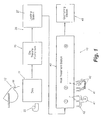
- Fig. 1 generally illustrates a metallurgical casting process 10. Casting processes are well known to those skilled in the art, and a traditional casting process will be described only briefly for reference purposes. It further will be understood by those skilled in the art that the present invention can be used with any type of casting process, including the formation of castings formed from aluminum, iron and various other types of metals and/or metal alloys.
- the molds also can include "precision sand mold” type molds generally formed from a granular material, such as silica, zircon or other sands, mixed with a binder.
- the binder is formed of a material that is soluble in one or more fluids, such as water, steam, organic solvents and the like.
- the binder may be formed of casting salts, containing a significant amount of soda ash, which are soluble in water and steam, phenolic resins, phenolic urethane "cold box” binder materials, or other suitable organic binder material, which are soluble in certain organic solvents and/or are thermally degradable.
- the molds and dies also may be semi-permanent sand molds having an outer mold wall formed from a sand and binder, a metal such as steel or a combination or both types of materials, or can include investment type castings/dies.
- a heating source or element such as a heated air blower or other suitable gas-fired or electric heater mechanism, or fluidized bed, 22 also generally is provided adjacent the pouring station 12 for preheating the molds 11.
- the molds are preheated to a desired temperature depending upon the metal or alloy used to form the casting. For example, for aluminum, the molds would be preheated to a range of approximately 400 - 600°C.
- Other varying preheating temperatures generally will be required for preheating various different metallic alloys or metals for forming the castings are well known to those skilled in the art and can include a wide range of temperatures above and below 400 - 600°C.
- some mold types may require lower process temperatures to prevent mold deterioration during pouring and solidification. In such cases, such where the metal processing temperatures are required to be higher, a suitable metal temperature control method, such as radiant or induction heating, can be employed to accomplish the process specified herein.
- the molds can be provided with internal heating sources or elements for heating the molds.
- the dies can include cavities or passages formed adjacent the casting and in which a heated fluid medium such as a thermal oil is received and/or circulated through the dies for heating the dies. Thereafter, thermal oils or other suitable media can be introduced and/or circulated through the dies, with the oil being of a lower temperature, for example 250°C - 300°C, to cool the castings and cause the castings to solidify.
- the mold and casting generally are removed from the pouring station 12 by a mold transfer mechanism 25, and are transferred to a loading station 26.
- the mold transfer mechanism can include a die transfer robot (not shown), winch or other type of conventionally known transfer mechanism for moving the molds from the pouring station to the loading station located in close proximity to the pouring station.
- the casting 13 is removed from its mold 11 prior to or at the loading station 26 ( Fig.
- the core apertures 21 ( Fig. 3 ) of the castings likewise are oriented or aligned in known positions for removal of the sand cores from the castings.
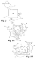
- the locating devices can include guide pins 33, such as shown in Fig. 3 , or can include notches or grooves, such as indicated by dashed lines 34 in Fig. 3 or other, similar devices for guiding or directing the castings into a desired indexed position or orientation.
- the guide pins 33 will be formed from a metal material such as cast iron or similar material having a high heat resistance, and are mounted to the base or any of the sidewalls of the saddle.
- Corresponding locator or guide openings 36 (shown in dashed lines) generally are formed in the casting during the casting process, such as by the use of guide pins mounted to the bottom or side walls of the molds, or through the use of degradable sand core-type materials.
- the guide pins are received within the corresponding guide openings of the castings so as to locate and maintain the castings in their desired, indexed positions having known, defined x, y and z coordinates, with the positions of the core access openings of the castings likewise oriented or aligned at known positions to enable more efficient and direct application of heat to the sand cores within the castings to enhance the dislodging and removal of the sand material for reclamation.
- the molds may include a steel or iron "chill" or insert having various design features of the casting imparted thereon for improved grain structure of the casting.
- These chills can be either removed after pouring or can be left with and remain part of the casting upon solidification of the molten metal of the casting.
- the chills, if left in the casting also can be used as locating devices to enable the castings to be located within their saddles in their desired alignment or position.
- the features or detail left by the removal of the chill can also act as a locating point for engagement of a guide pin or other locating device within the saddle so as to hold each casting in its desired, indexed position.
- the castings are then moved in their saddles into and through a heat treatment station 40 for heat treatment, core removal and sand reclamation if desired.
- the saddles are generally conveyed or moved through the heat treatment station on a conveyor or rails so that the castings are maintained in their known indexed positions as they are moved through the heat treatment station.
- the heat treatment station 40 generally includes a heat treatment furnace, such as a gas fired furnace, and generally includes a series of treatment zones or chambers for heat treating each casting and removal and reclamation of the sand material of the sand cores.
- Such heat treatment zones can include various types of heating environments such as conduction, including the use of fluidized beds, and convection, such as using heated air flows.
- Other heating chambers or application means could include induction and radient heating environments.
- the number of treatment zones and/or environments can be divided into as many or as few number of zones as the individual applications may require to heat treat and remove the sand cores therefrom, and each casting typically is kept inside its mold until a saddle is available to move it through a heat treatment station. It is further possible to additionally age the castings within the heat treatment station 40 if so desired.
- the heat treatment station 40 includes a heat and/or fluid source or element 41, here illustrated as including a series of nozzle stations 42 positioned at spaced intervals along the length of the heat treatment station to enhance the heat treatment and sand core removal from the castings.
- the number of nozzle stations positioned along the heat treatment station can vary as needed, depending upon the core print or design of the casting.
- Each of the nozzle stations or assemblies 42 includes a series of nozzles 43, mounted and oriented at known or registered positions corresponding to the known, indexed positions of the castings being passed therethrough in their saddles.
- the number of nozzles in each nozzle station is variable, depending upon the core prints of the castings, such that different types of castings having differing core prints can utilize an optionally different arrangement or number of nozzles per nozzle station.
- the nozzles typically are controlled through a control system that can be operated remotely so as to engage or disengage various ones of the nozzles at the different nozzle stations as needed, depending upon the design or core prints of the castings passing through the heat treatment station.
- Each nozzle 43 generally is mounted in a predetermined position and/or orientation, aligned with one of the core apertures or access openings or core prints or a set of core apertures formed in the castings according to the known, indexed positions or orientations of the castings within the saddles.
- Each of the nozzles is supplied with a fluid media, typically under high pressure and heated, which includes one or more components in which one or more components of the core are soluble.
- the fluid media used may include air, water, steam, thermal oils, other organic solvents and mixtures thereof.
- the fluids are directed at the core openings under high pressure, so as to develop relatively high fluid velocities, typically approximately 1,000 FPM to approximately 15,000 FPM, although greater or lesser velocities and thus pressures also can be used as required for the particular casting application.
- the pressurized fluid flows, streams or blasts applied to the castings by the nozzles tend to impact or contact the cores within the castings and help heat treat the castings and cause the binder materials of the sand cores to at least partially dissolve, degrade or otherwise break down.
- the core binder materials When the core binder materials are exposed to fluid in which it is soluble, it begins to dissolve in the fluid. Dissolution of the binder causes the chemical bonds linking the binder molecules to each other and to the filler particles to break down.
- the sand of the sand cores tends to be removed or cleaned from the castings through the core apertures or access openings with the passage of the fluid flows through the castings for recovery and reclamation of the sand.
- the nozzles 43 of each nozzle assembly or station 42 further can be adjusted to different nozzle positions depending upon the characteristics of the castings and the pressure of the fluid flows or blasts can also be adjusted.
- the adjustment of the nozzles can be accomplished remotely, such as through the use of robotically movable or positionable nozzles.
- the fluids from the nozzles also can be applied at different temperatures, depending upon which zones within the heat treatment station of the nozzles from which they are dispensed are located, so that the fluid flows will not interfere negatively with the heat treatment process for the castings as they are moved through the heat treatment furnace or station.
- each nozzle station can be moved between various nozzle positions including moving between a rest position and an application position, or between several application positions, oriented toward and/or aligned with the core apertures or access openings upon movement of the castings into different zones or stations within the heat treatment station so as to strategically direct high pressure flows of a heated fluid media toward the different core apertures or access openings to cause the sand cores and/or sand molds to be broken up and dislodged from the castings for removal of the sand cores therefrom.
- each casting is removed from the heat treatment station 40 and typically is moved into a quenching station 45.
- the quenching station 45 typically includes a quench tank filled with a cooling fluid, such as water or other known material in which each casting is immersed for cooling and quenching.
- the capacity and size of the quench tank generally is a function of the castings being formed and the specific heat of the metal or metal alloy comprising the castings and the temperatures to which each casting has been heated.
- the quenching station can include one or a series of nozzles for applying cooling fluid to the castings for quenching and/or further binder degradation and core removal.
- the pre-heating of the permanent metal dies tends to substantially maintain and minimize loss of temperature of the castings being formed within the permanent metal dies at or near the heat treatment temperature for the castings as the permanent metal dies are transferred from the pouring station and to at least partially heat treat the castings as they solidify, and to enhance the heat treatment of the castings by reducing heat treatment times since the castings do not have to be significantly reheated to raise their temperature to levels necessary for heat treatment.
- Active temperature control of the mold or die also permits careful control of metal solidification rates within the mold or die.
- the process may include prescribed, controlled cooling rates for the molten metal, such that the metal solidifies, as a whole or in specific areas, to produce optimized metallurgical microstructures in the solid metal.
- aluminum alloys may achieve higher properties if the Secondary Dendrite Arm Spacing (SDAS) of the solidified metal is sufficiently small so as to permit more effective solution of the elements.
- SDAS is typically determined by the cooling rate of the casting or specific area of the casting; thus controlling cooling rates during solidification with the present invention generally will produce the desired SDAS, and hence improved properties in the casting.
- the transfer mechanism 59 generally can include a transfer robot, winch, conveyor, carousel or other type of conventionally known transfer mechanism for moving the molds from the pouring station to the loading station.
- the transfer mechanism positions each mold in a known, indexed position at the loading station, with the x, y and z coordinates of the dies being located in a known orientation or alignment prior for heat treatment.
- the molds thereafter generally are moved into a heat treatment station 62 to at least partially heat treat the castings and break down their sand cores and/or sand molds for removal.
- the heat treatment station 62 generally includes a heat treatment furnace, typically a gas fired furnace, having a series of treatment zones or chambers for applying heat to the dies and thus to the castings, for at least partial heat treatment of the castings "in-die” or in-mold.
- the number of nozzle stations and the number of nozzles at each station can be varied as needed for providing heat and/or fluid flows in varying degrees and/or amounts to the dies for heat treating the castings therewithin to enable control of the heating of the dies and thus the castings, and the adjustment of the heating to different stages of heat treatment of the castings.
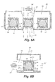
- Each of the nozzles generally supplies a flow of a heated fluid media that is directed toward the molds and typically toward a specific die access opening or set of die access openings of each mold as indicated in Figs. 5A and 5B .
- the fluid medium applied to the molds typically includes heated air, water, steam, thermal oils, organic solvents, or mixtures thereof, or other conventionally known fluid media that are supplied under high pressure and at varying temperatures to heat the molds, with the temperature of the fluid media flows supplied by the nozzles being controlled to conform to different heat treatment stages as the casting is passed through the different nozzle stations of the heat treatment station.
- the introduction of the heated fluid media into the molds through the access openings further generally tends to cause the core binder to dissolve so as to cause the cores to at least partially degrade and be dislodged and/or removed from the castings during heat treatment, with the dislodged sand material passing through the access openings with the draining of the fluids therefrom.
- the molds also potentially can be at least partially opened as they pass through the nozzle stations for more direct application of the heated fluids media to the castings and core openings thereof for heat treatment and sand core removal.
- nozzles 66 move about the molds in the direction of arrows 67 and 68, they apply a heated, pressurized fluid media F against the dies, typically directed toward and into the access openings 56, so as to raise and maintain the temperature of the dies at a sufficient temperature for heat treating the metal casting therewithin as the molten metal of the castings is solidified.
- the part may be kept in the mold to complete the heat treatment before removal from the mold and quenching.
- the various application or nozzle positions of the movable nozzles generally are determined or set according to the known x, y and z coordinates of the molds, and thus their access openings, at the pouring station or upon the positioning or locating of the dies at the loading station by the die transfer mechanism.
- the molds within their castings therein, can be immersed in a fluid bed (as indicated at 73 in Fig. 6 ) such as disclosed in U.S. Patent Nos. 5,294,994 ; 5,565,046 ; and 5,738,162 ), the disclosures of which have been incorporated by reference.
- the molds and castings will be immersed in the fluid bed for heat-up, temperature control and/or mold/core sand removal.
- the molds typically are permanent type metal dies formed with cavities or chambers (indicated by dashed lines 69 in Figs. 5A and 5B ) in close proximity to the internal cavity 53 in which the casting is formed.
- a heated fluid media such as heated water, steam, thermal oils or other fluid materials capable of readily retaining heat, is then be supplied to the die structure, such as through the ports or access openings 56 ( Figs. 4 - 5B ), received within the internal cavities. This introduction of heated media into the dies tends to increase and help maintain the temperature of the casting at a desired level needed for heat treatment.
- FIG. 6 - 8 Various alternative embodiments of heat treatment stations or chambers for use in the systems of the present invention are shown in Figs. 6 - 8 , and can be used separately or in conjunction with each other to supplement or replace the nozzle stations as discussed above with additional heat treatment chambers having various types of alternative, different heat sources 63, which supply or direct energy toward the molds for raising and maintaining the temperature of the molds at the required temperature for heat treating the castings therein.
- the molds 51 generally are sand mold packs and are placed on a conveyor or transport mechanism 71 for movement through the heating chamber 70 as indicated by arrows 72.
- the heating chamber 70 typically is an elongated furnace chamber having an insulated floor, sides, and ceiling and, as illustrated in the embodiment of Fig. 6 , a fluidized bed 73, typically formed from foundry sand and sand dislodged from the cores and sand molds for further degrading of the binder and reclaiming of the sand.
- the heat source 63 is a radiant energy source 74, typically mounted in the ceiling of the heating chamber 70, although it will be understood by those skilled in the art that the radiant energy source can also be mounted in side walls. In addition, multiple radiant energy sources can be used, mounted in the side walls, overhead and/or below the molds as they are moved through the heating chamber 70 on the conveyor or transport mechanism.
- An example of a radiant energy source will be a infrared emitter or other known type of radiant energy source.
- the radiant energy source generally will direct radiant energy at approximately 400 - 650°C toward the dies passing through the heating chamber, typically being directed against the sides and/or top of each mold as illustrated by arrows 74.
- the molds, and thus the castings therewithin, are subjected to the radiant energy source for a desired length of time, depending upon the metal of the castings being heat treated.
- the radiant energy generally is absorbed by the molds, causing the temperature of the molds to correspondingly increase so as to heat the molds and thus the castings therewithin from the outside to the inside of the molds.
- the heat source 63 of the heating chamber 80 generally includes an induction energy source 83 for applying induction energy to the mold packs, and thus to the castings and sand cores 54 and 55 contained therewithin and can include a fluid bed along its floor for collection and reclamation of sand dislodged from the sand cores and sand molds.
- the induction energy source generally can include a conduction coil, microwave energy source or other known induction energy sources or generators, and, as with the radiant energy source of Fig. 6 , can be positioned in the ceiling of the heating chamber 80, above the molds, along the sides of the heating chamber, or both.
- the induction energy source will create a high energy field of waves, indicated by arrows 84, that are directed toward the top and/or sides of the molds 51 and are of a particular frequency or frequencies that will be absorbed by the sand cores 55 so as to cause the temperature of the sand cores and thus the castings to be increased to correspondingly heat treat the metal castings within the mold packs by heating the casting and thus the molds from the inside out.
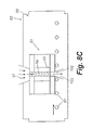
- the oxygen chamber generally includes a high pressure, upstream side 94 and a low pressure, downstream side 96 that are positioned opposite each other so that a flow of oxygen is passed therebetween.
- the castings and molds will enter the autoclave heating chamber approximately at atmospheric pressure.
- the pressure in the chamber is increased and the flow of heated oxygen gas is directed at and is forced through the mold packs, as indicated by arrows 97 ( Fig. 8A ) and 97' ( Fig. 8B ).
- the oxygen flow is driven into and through the molds and to the inner cores of the castings.
- the molds further can be formed with or to include a vacuum port or opening, indicated by 102, formed along either the upper or lower surfaces of the molds.
- a suction or vacuum, indicated at 103, is applied at the port 102 formed in each mold for drawing the oxygen gas into and through or molds.
- the molds are gas or air tight and can include a plug (not shown) for sealing the port 102, but which can be removed from the port 102 to provide a suction or vacuum point along the molds as the oxygen gas is drawn or flows through the molds.
- the molds and their castings are further supplied with heat energy from the enhanced combustion of the binder material thereof and the oxygen gas, which thus acts as a heat source to increase the temperature of the castings in the mold packs, while at the same type breaking down the binder of the molds and/or sand cores for ease of removal and reclamation.
- a radiant energy heat treatment chamber 70 can be mounted or positioned at an upstream end 106 ( Fig. 9 ) of the heat treatment unit 105.
- the radiant heating chamber 70 generally heats the molds to a temperature sufficient to initiate the combustion of the binder of the molds while the same time heating the castings therewithin to begin the heat treatment of the castings while still in-mold.
- a further heating chamber 80 having an induction energy source therein, generally will be positioned downstream from the radiant heating chamber 70.
- the heating chamber 80 will apply induction energy via a high energy field of electromagnetic waves as discussed above, which generally will tend to further promote the combustion of the binder and heat treatment of the castings within the molds.
- the application of the inductive energy waves will tend to cause cracking or breaking of the sand molds into sections or pieces to further promote the breakdown of the sand molds.
- an oxygen heating chamber 90 such as shown in Figs. 8A - 8C , will be positioned downstream from heating chamber 80.
- the forced flow of oxygen through the chamber promotes and enhances the combustion of the sand molds and sand cores.
- the binder of the sand molds having been raised to a combustion temperature and the molds becoming cracked in the heating chambers 70 and 80, and/or pieces thereof becoming broken or dislodged, the further enhancement of the combustion of the binder of the sand cores within the oxygen heating chamber 90 tends to promote the increased breakdown and dislodging of the sand molds and sand cores form the castings.
- the time required for breakdown and removal of the sand molds and sand cores is decreased so that the castings are more rapidly exposed directly to the heating environment of the heat treating unit, while at the same time, the rapid breakdown and combustion of the binder of the sand molds further enhances the heating of the castings to their solution heat treatment temperatures.
- the raising of the temperature of the molds to the heat treatment temperature for heat treating the castings further enhances the breakdown and combustion of the combustible organic binders of the sand cores and/or sand molds, if used, so as to further reduce the time required for the heat treatment and dislodging and reclamation of the sand cores and sand molds of the casting process.
- the castings typically are removed from their molds and can be moved to an additional heat treatment station for completion of the heat treatment of the castings, as needed, and for sand core removal and possible reclamation of the sand materials of the cores.
- the castings are then moved into a quenching station 110 for quenching and cooling of the castings.
- the castings can be removed from their dies and transferred directly to the quenching station.
- the quenching station 110 typically includes a quench tank having a cooling fluid such as water or other known coolant material, but the quenching station can also comprise a chamber having one or a series of nozzles, indicated at 111 in Fig.
- the quenching also can take place in contiguous ancillary quenching equipment that is in close proximity to the pouring station so that cycle time and heat variations can be minimized for the setting and treatment of the molten metal material of the castings within the molds.
- the castings can be removed from the molds and transferred to the quench tank of the quench station for cooling the castings before further processing, and sand removed from the castings then can be reclaimed for later reuse.
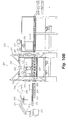
- Figs. 10A and 10B illustrate still a further embodiment 200 of the present invention for the enhanced heat treatment and breakdown and removal of sand cores and/or sand molds from a series of castings 201.
- a molten metal or metal alloy M ( Fig. 10A ) is poured into a mold, such as a cast iron or other permanent type die or a semi-permanent or precision sand mold 202 at a pouring or casting station 203.
- the molds generally include an internal cavity 204 in which the molten metal is received and solidified to form the casting 201 and in which a sand core 206 typically is provided for forming ports or other interior detail for the casting.
- the molds in this embodiment will also include a series of ports or mold access openings 207 that extend through the side walls 208 of the molds. These ports provide an access to the interior cavity or chamber 204, and thus the casting being formed therein, for direct application of heat to the castings while "in-mold” and for assistance in dislodging and removal of the sand cores 206 therefrom.
- the castings thereafter are removed from the casting or pouring station 203 by a transfer mechanism 210, which transfers the molds with their castings therewithin or which first removes the castings and thereafter transfers the castings individually to an inlet conveyor or loading station, indicated by 211 in Fig. 10A , for a heat treatment line or unit 212.
- the transfer mechanism can include a crane or robotic arm 213, as illustrated in Fig. 10B , including a gripping or engaging portion 214 that is adapted to engage, grip and lift the molds and/or castings and is mounted to one end of a body or articulateable arm that is movably attached to a base portion 214.
- the crane or arm 213 thus is moveable between a transfer position at the pouring station and the inlet 211 of the heat treatment unit or line 212 as indicated in Fig. 10A .
- various other systems or devices for transferring the castings from the pouring station to the heat treatment line also can be used, such as an overhead crane, winch, conveyor, hoist, carousel, push rods and other known material handling devices.
- the transfer mechanism 210 will position the molds or castings themselves at the inlet or loading station of the heat treatment line with the molds or castings being located in a known, indexed position with their X, Y and Z coordinates in a known orientation or alignment prior to heat treatment.
- the molds and/or castings will be introduced into a process temperature control station or pretreatment chamber 218 prior to introduction into the heat treatment furnace 219 of the heat treatment unit 212.
- the castings will be permitted to cool a sufficient amount as is necessary for the molten metal within the molds to solidify and harden to form the castings.
- the metal of the castings is cooled below the point at which it has solidified, it reaches a process control temperature below which the time required to both raise the temperature of the metal of the castings back up to a solution heat treatment temperature and for performing the heat treatment thereof is significantly increased.
- This process control temperature generally varies depending upon the metal and/or metal alloy being used to form the casting, generally ranging from temperatures of approximately 400°C or lower for some metals or alloys such as aluminum/copper alloys, up to approximately 1000°C - 1300°C or greater for other metals or alloys such as iron and steel.
- the process control temperature can generally range from about 400°C to about 470°C, which temperatures generally fall below the solution heat treatment temperatures for most aluminum/copper alloys, which instead range from approximately 475°C to approximately 490°C and occasionally higher.
- a casting is permitted to cool below its process control temperature for approximately 10 minutes, it can take as much as 40 minutes or more of additional heat treatment/soaking time at the solution heat treatment temperature for the metal of the castings in order to properly and completely heat treat the casting.
- the castings are one of several that are loaded into a basket or tray for processing numerous castings in a batch at a single time, it generally has been necessary to heat treat the entire batch of castings for a time and to an extent necessary to completely heat treat the casting(s) with the lowest temperature. This accordingly will require that the majority of the castings in the batch will be subjected to heat treatment for a significantly longer period of time than required to ensure complete treatment of all castings in the batch, thus resulting in wasted energy and increased processing times for the castings.
- the process temperature control station 218 generally is an elongated tunnel or unit having side walls 221, a ceiling 222 and a floor or bottom 223 through which a conveyor or similar transport mechanism 224 is extended for conveying the molds and/or castings therethrough.
- the ceiling 222 and sides 221 of the process temperature control station 218 generally are formed from or have applied thereto a radiant material such as a metal, metal foil, ceramic or other types of composite materials that radiate or direct heat inwardly toward the castings so as to thus define a radiant chamber 226 within the process temperature control station.
- the cooling of the castings is arrested by the application of heat from heat sources 227. Thereafter, the castings are generally maintained at or above their process control temperature, which temperature generally varies depending upon the metal used to form the castings until the castings are introduced into the heat treatment furnace 219. As a result, the castings are permitted to cool sufficiently to allow the metal thereof to solidify, while the cooling of the castings is arrested at or above the process control temperature. As a result, the castings are introduced into the heat treatment furnace, they can be more efficiently and rapidly brought to their solution heat treatment temperatures and subjected to substantially complete heat treatment more efficiently.
- the castings and/or molds with the castings therein will be passed from the process temperature control station directly into the heat treatment furnace 219 of the heat treatment line.
- the heat treatment furnace generally will comprise a heat treatment furnace or station as discussed above with respect to the embodiments of Figs. 1 and 4 .
- An example of such a heat treatment furnace for heat treatment and at least partial breakdown and/or reclamation of the sand cores and/or sand molds from the castings is illustrated in U.S. Patent Nos. 5,294,994 ; 5,565,046 ; 5,738,162 , and 6,217,317 , the disclosures of which have previously been incorporated by reference.
- the heat treatment furnace generally includes a series of treatment zones, chambers or stations, indicated by 236 in Fig. 104, for applying heat to the molds and/or castings for heat treatment of the castings.
- the castings can be heat treated while at least partially "in-mold", while at the same time the sand molds in which the castings are contained can be rapidly broken down and removed from the castings and the sand materials thereof reclaimed.
- the heat treatment zones or chambers also can include a variety of different heating environments such as conductive or convection heating chambers, radiant heating chambers or chambers in which an enhanced or negative air pressure draws a flow of oxygen through the sand molds of the castings to enhance the combustion of the binders of the sand molds.
- the heat treatment furnace further can be divided into as many or as few treatment zones as an individual application may require depending upon the castings being processed.
- the castings After passing through the heat treatment furnace 219, the castings thereafter generally are removed from the heat treatment furnace and can be transported to a quench station 240 ( Fig. 10A ) for quenching or further processing.
- the present invention enables the reduction or elimination of a requirement for further heat treating of the castings once removed from the molds, which are heated to provide solution heating time and cooled to provide the quenching effect necessary, while in-mold, so as to significantly reduce the amount of heat treatment/processing time required for forming metal castings.
- the present invention further enables an enhanced or more efficient heat treatment and breakdown and removal of sand cores within the castings by directing fluid flows at the castings at preset positions, corresponding to known orientations or alignments of the castings and/or the molds with the castings contained therein as they are passed through a heat treatment station.
Landscapes
- Engineering & Computer Science (AREA)
- Mechanical Engineering (AREA)
- Chemical & Material Sciences (AREA)
- Physics & Mathematics (AREA)
- Thermal Sciences (AREA)
- Crystallography & Structural Chemistry (AREA)
- Materials Engineering (AREA)
- Metallurgy (AREA)
- Organic Chemistry (AREA)
- Molds, Cores, And Manufacturing Methods Thereof (AREA)
- Casting Devices For Molds (AREA)
Applications Claiming Priority (2)
| Application Number | Priority Date | Filing Date | Title |
|---|---|---|---|
| US40196902P | 2002-08-08 | 2002-08-08 | |
| EP03785083A EP1575722A2 (de) | 2002-08-08 | 2003-08-07 | Verfahren und vorrichtung für wärmebehandlung und sandentfernung für gussteile |
Related Parent Applications (1)
| Application Number | Title | Priority Date | Filing Date |
|---|---|---|---|
| EP03785083A Division EP1575722A2 (de) | 2002-08-08 | 2003-08-07 | Verfahren und vorrichtung für wärmebehandlung und sandentfernung für gussteile |
Publications (2)
| Publication Number | Publication Date |
|---|---|
| EP2027953A2 true EP2027953A2 (de) | 2009-02-25 |
| EP2027953A3 EP2027953A3 (de) | 2010-01-20 |
Family
ID=31715765
Family Applications (3)
| Application Number | Title | Priority Date | Filing Date |
|---|---|---|---|
| EP03785083A Withdrawn EP1575722A2 (de) | 2002-08-08 | 2003-08-07 | Verfahren und vorrichtung für wärmebehandlung und sandentfernung für gussteile |
| EP08167058A Withdrawn EP2027953A3 (de) | 2002-08-08 | 2003-08-07 | Verfahren und Vorrichtung zur Wärmebehandlung und Sandentfernung für Gussteile |
| EP08167057A Withdrawn EP2027952A3 (de) | 2002-08-08 | 2003-08-07 | Verfahren und Vorrichtung zur Wärmebehandlung und Sandentfernung für Gussteile |
Family Applications Before (1)
| Application Number | Title | Priority Date | Filing Date |
|---|---|---|---|
| EP03785083A Withdrawn EP1575722A2 (de) | 2002-08-08 | 2003-08-07 | Verfahren und vorrichtung für wärmebehandlung und sandentfernung für gussteile |
Family Applications After (1)
| Application Number | Title | Priority Date | Filing Date |
|---|---|---|---|
| EP08167057A Withdrawn EP2027952A3 (de) | 2002-08-08 | 2003-08-07 | Verfahren und Vorrichtung zur Wärmebehandlung und Sandentfernung für Gussteile |
Country Status (6)
| Country | Link |
|---|---|
| EP (3) | EP1575722A2 (de) |
| JP (1) | JP2006504531A (de) |
| CN (1) | CN100335208C (de) |
| CA (1) | CA2495514C (de) |
| MX (1) | MXPA05001393A (de) |
| WO (1) | WO2004014581A2 (de) |
Cited By (1)
| Publication number | Priority date | Publication date | Assignee | Title |
|---|---|---|---|---|
| WO2019185437A1 (en) * | 2018-03-30 | 2019-10-03 | Basf Se | Cleaning of foundry molds |
Families Citing this family (16)
| Publication number | Priority date | Publication date | Assignee | Title |
|---|---|---|---|---|
| CA2571176C (en) * | 2004-06-28 | 2013-05-28 | Consolidated Engineering Company, Inc. | Method and apparatus for removal of flashing and blockages from a casting |
| US20060103059A1 (en) * | 2004-10-29 | 2006-05-18 | Crafton Scott P | High pressure heat treatment system |
| US7838542B2 (en) * | 2006-06-29 | 2010-11-23 | Kinex Pharmaceuticals, Llc | Bicyclic compositions and methods for modulating a kinase cascade |
| FI121652B (fi) | 2009-04-24 | 2011-02-28 | Waertsilae Finland Oy | Menetelmä onkalon sisältävän esineen valmistamiseksi |
| IT1399945B1 (it) * | 2010-04-29 | 2013-05-09 | Turbocoating S P A | Metodo e apparato per rimuovere ricoprimenti ceramici, con sabbiatura di anidride carbonica allo stato solido. |
| FR2978927B1 (fr) | 2011-08-09 | 2013-09-27 | Snecma | Procede de fonderie de pieces metalliques monocristallines |
| EP3041623B1 (de) * | 2013-09-04 | 2017-06-07 | Nemak, S.A.B. de C.V. | Verfahren zum entformen eines aus leichtmetallschmelze gegossenen gussteils aus einer giessform |
| WO2015115231A1 (ja) * | 2014-01-28 | 2015-08-06 | 有限会社ウインズテック | 砂中子の除去方法とその装置 |
| DE102014221994B4 (de) * | 2014-10-29 | 2023-03-30 | Bayerische Motoren Werke Aktiengesellschaft | Herstellen und Bearbeiten von Gussteilen |
| CN109070191B (zh) * | 2016-04-28 | 2022-01-25 | 阿洛泰克利米德有限责任公司 | 消融铸造方法 |
| CN108213341A (zh) * | 2017-05-08 | 2018-06-29 | 宁夏迪艾投资合伙企业(有限合伙) | 一种磁控震动去除3d打印砂型多余砂料的装置及其方法 |
| CN111906292A (zh) * | 2019-05-08 | 2020-11-10 | 潜山县凯创橡塑机械制造有限公司 | 一种合金衬套生产线 |
| CN110538983A (zh) * | 2019-10-08 | 2019-12-06 | 安洁无线科技(苏州)有限公司 | 水道板低压铸造工艺 |
| CN111482593A (zh) * | 2020-04-27 | 2020-08-04 | 遂昌县鑫鼎特种铸造有限公司 | 一种铸造生产线 |
| CN113462864B (zh) * | 2021-06-08 | 2022-11-22 | 中国科学院金属研究所 | 一种高温合金空心铸件带芯进行真空热处理的方法 |
| US12594597B2 (en) * | 2024-01-16 | 2026-04-07 | Alotech Limited R & D, LLC | Multi indirect injection solidification technology |
Citations (6)
| Publication number | Priority date | Publication date | Assignee | Title |
|---|---|---|---|---|
| US5294094A (en) | 1989-09-29 | 1994-03-15 | Consolidated Engineering Company | Method and apparatus for heat treating metal castings |
| US5294994A (en) | 1992-04-06 | 1994-03-15 | Digital Equipment Corporation | Integrated computer assembly |
| US5565046A (en) | 1989-09-29 | 1996-10-15 | Consolidated Engineering Company, Inc. | Heat treatment of metal castings and integrated sand reclamation |
| US5738162A (en) | 1997-02-20 | 1998-04-14 | Consolidated Engineering Company, Inc. | Terraced fluidized bed |
| US6217317B1 (en) | 1998-12-15 | 2001-04-17 | Consolidated Engineering Company, Inc. | Combination conduction/convection furnace |
| US6638302B1 (en) | 1996-12-30 | 2003-10-28 | Sorin Biomedica Cardio S.P.A. | Stent for angioplasty and associated production process |
Family Cites Families (16)
| Publication number | Priority date | Publication date | Assignee | Title |
|---|---|---|---|---|
| CH622726A5 (en) * | 1976-12-09 | 1981-04-30 | Kohlswa Jernverks Ab | Method for knocking out silicate-bound moulding compound from a mould filled with casting |
| JPS5653867A (en) * | 1979-10-03 | 1981-05-13 | Sanken Sangyo Kk | Method and device for shaking out sand from aluminum casting prepared in sand core |
| JPS59219410A (ja) * | 1983-05-27 | 1984-12-10 | Trinity Ind Corp | 砂型鋳造品の熱処理装置 |
| JPH0191957A (ja) * | 1987-03-03 | 1989-04-11 | Mazda Motor Corp | 鋳物の熱処理方法 |
| JPH04500780A (ja) * | 1987-12-08 | 1992-02-13 | サハリ、ハリ | 金属鋳造に用いられる鋳型と中子の調製方法 |
| US5350160A (en) * | 1989-09-29 | 1994-09-27 | Consolidated Engineering Company | Method and apparatus for heat treating metal castings |
| US5089186A (en) * | 1990-07-11 | 1992-02-18 | Advanced Plastics Partnership | Process for core removal from molded products |
| US5262100A (en) * | 1990-07-11 | 1993-11-16 | Advanced Plastics Partnership | Method of core removal from molded products |
| ES2107438T5 (es) * | 1991-05-24 | 2004-04-01 | Consolidated Engineering Company, Inc. | Metodo y aparato para tratar termicamente piezas coladas metalicas. |
| US6241000B1 (en) * | 1995-06-07 | 2001-06-05 | Howmet Research Corporation | Method for removing cores from castings |
| US5829509A (en) * | 1996-02-23 | 1998-11-03 | Consolidated Engineering Co, Inc. | Integrated system and process for heat treating castings and reclaiming sand |
| US5778963A (en) * | 1996-08-30 | 1998-07-14 | United Technologies Corporation | Method of core leach |
| US6253830B1 (en) * | 1996-09-30 | 2001-07-03 | Procedyne Corp. | Apparatus and method for sand core debonding and heat treating metal castings |
| IT1295224B1 (it) * | 1997-10-14 | 1999-05-04 | Magneti Marelli Spa | Macchina per la rimozione di anime in sale imprigionate in manufatti pressocolati o stampati ad iniezione. |
| EP1225993B1 (de) * | 1999-07-29 | 2008-06-11 | Consolidated Engineering Company, Inc. | Wärmebehandlung und sandentfernung von gussteilen |
| US6672367B2 (en) * | 1999-07-29 | 2004-01-06 | Consolidated Engineering Company, Inc. | Methods and apparatus for heat treatment and sand removal for castings |
-
2003
- 2003-08-07 JP JP2004527921A patent/JP2006504531A/ja active Pending
- 2003-08-07 WO PCT/US2003/024928 patent/WO2004014581A2/en not_active Ceased
- 2003-08-07 EP EP03785083A patent/EP1575722A2/de not_active Withdrawn
- 2003-08-07 CN CNB038217759A patent/CN100335208C/zh not_active Expired - Fee Related
- 2003-08-07 EP EP08167058A patent/EP2027953A3/de not_active Withdrawn
- 2003-08-07 EP EP08167057A patent/EP2027952A3/de not_active Withdrawn
- 2003-08-07 CA CA002495514A patent/CA2495514C/en not_active Expired - Fee Related
- 2003-08-07 MX MXPA05001393A patent/MXPA05001393A/es active IP Right Grant
Patent Citations (6)
| Publication number | Priority date | Publication date | Assignee | Title |
|---|---|---|---|---|
| US5294094A (en) | 1989-09-29 | 1994-03-15 | Consolidated Engineering Company | Method and apparatus for heat treating metal castings |
| US5565046A (en) | 1989-09-29 | 1996-10-15 | Consolidated Engineering Company, Inc. | Heat treatment of metal castings and integrated sand reclamation |
| US5294994A (en) | 1992-04-06 | 1994-03-15 | Digital Equipment Corporation | Integrated computer assembly |
| US6638302B1 (en) | 1996-12-30 | 2003-10-28 | Sorin Biomedica Cardio S.P.A. | Stent for angioplasty and associated production process |
| US5738162A (en) | 1997-02-20 | 1998-04-14 | Consolidated Engineering Company, Inc. | Terraced fluidized bed |
| US6217317B1 (en) | 1998-12-15 | 2001-04-17 | Consolidated Engineering Company, Inc. | Combination conduction/convection furnace |
Cited By (2)
| Publication number | Priority date | Publication date | Assignee | Title |
|---|---|---|---|---|
| WO2019185437A1 (en) * | 2018-03-30 | 2019-10-03 | Basf Se | Cleaning of foundry molds |
| CN111936252A (zh) * | 2018-03-30 | 2020-11-13 | 巴斯夫欧洲公司 | 铸造模具的清洁 |
Also Published As
| Publication number | Publication date |
|---|---|
| JP2006504531A (ja) | 2006-02-09 |
| CN100335208C (zh) | 2007-09-05 |
| AU2003259701A1 (en) | 2004-02-25 |
| CA2495514A1 (en) | 2004-02-19 |
| WO2004014581A3 (en) | 2005-10-13 |
| MXPA05001393A (es) | 2005-04-28 |
| CN1753746A (zh) | 2006-03-29 |
| HK1087664A1 (en) | 2006-10-20 |
| EP2027952A2 (de) | 2009-02-25 |
| WO2004014581A2 (en) | 2004-02-19 |
| EP1575722A2 (de) | 2005-09-21 |
| EP2027952A3 (de) | 2010-01-20 |
| EP2027953A3 (de) | 2010-01-20 |
| CA2495514C (en) | 2009-11-03 |
Similar Documents
| Publication | Publication Date | Title |
|---|---|---|
| US6672367B2 (en) | Methods and apparatus for heat treatment and sand removal for castings | |
| US20070289715A1 (en) | Methods and apparatus for heat treatment and sand removal for castings | |
| US7290583B2 (en) | Methods and apparatus for heat treatment and sand removal for castings | |
| CA2495514C (en) | Methods and apparatus for heat treatment and sand removal for castings | |
| AU2002239968A1 (en) | Integrated metal processing facility | |
| CA2391349C (en) | A method and apparatus for the heat treatment and sand core removal for castings | |
| US7275582B2 (en) | Methods and apparatus for heat treatment and sand removal for castings | |
| US20080011443A1 (en) | Methods and apparatus for heat treatment and sand removal for castings | |
| US6217317B1 (en) | Combination conduction/convection furnace | |
| AU2003259701B2 (en) | Methods and apparatus for heat treatment and sand removal for castings | |
| HK1087664B (en) | Methods and apparatus for heat treatment and sand removal for castings | |
| HK1080784B (en) | Heat treatment and sand removal for castings |
Legal Events
| Date | Code | Title | Description |
|---|---|---|---|
| PUAI | Public reference made under article 153(3) epc to a published international application that has entered the european phase |
Free format text: ORIGINAL CODE: 0009012 |
|
| AC | Divisional application: reference to earlier application |
Ref document number: 1575722 Country of ref document: EP Kind code of ref document: P |
|
| AK | Designated contracting states |
Kind code of ref document: A2 Designated state(s): AT BE BG CH CY CZ DE DK EE ES FI FR GB GR HU IE IT LI LU MC NL PT RO SE SI SK TR |
|
| RIN1 | Information on inventor provided before grant (corrected) |
Inventor name: RUEGG, FRANZ Inventor name: CRAFTON, SCOTT, P. Inventor name: LEWIS, JAMES, L., JR. Inventor name: CRAFTON, PAUL, M. Inventor name: FRENCH, IAN Inventor name: KNOBLOCH, VOLKER, R. |
|
| PUAL | Search report despatched |
Free format text: ORIGINAL CODE: 0009013 |
|
| AK | Designated contracting states |
Kind code of ref document: A3 Designated state(s): AT BE BG CH CY CZ DE DK EE ES FI FR GB GR HU IE IT LI LU MC NL PT RO SE SI SK TR |
|
| STAA | Information on the status of an ep patent application or granted ep patent |
Free format text: STATUS: THE APPLICATION IS DEEMED TO BE WITHDRAWN |
|
| AKY | No designation fees paid | ||
| 18D | Application deemed to be withdrawn |
Effective date: 20100302 |
|
| REG | Reference to a national code |
Ref country code: DE Ref legal event code: 8566 |