EP2027963B1 - Komponent mit einem schlagbohrförmigen Durchgangsloch mit Coanda-Effekt und Verfahren zur herstellung dieses Loches unter Verwendung vom Schlagbohrlaserverfahren - Google Patents
Komponent mit einem schlagbohrförmigen Durchgangsloch mit Coanda-Effekt und Verfahren zur herstellung dieses Loches unter Verwendung vom Schlagbohrlaserverfahren Download PDFInfo
- Publication number
- EP2027963B1 EP2027963B1 EP08162416A EP08162416A EP2027963B1 EP 2027963 B1 EP2027963 B1 EP 2027963B1 EP 08162416 A EP08162416 A EP 08162416A EP 08162416 A EP08162416 A EP 08162416A EP 2027963 B1 EP2027963 B1 EP 2027963B1
- Authority
- EP
- European Patent Office
- Prior art keywords
- crater
- primary
- component
- hole
- shaped
- Prior art date
- Legal status (The legal status is an assumption and is not a legal conclusion. Google has not performed a legal analysis and makes no representation as to the accuracy of the status listed.)
- Not-in-force
Links
- 238000009527 percussion Methods 0.000 title claims description 33
- 238000000034 method Methods 0.000 title claims description 19
- 230000000694 effects Effects 0.000 title claims description 8
- 238000001816 cooling Methods 0.000 claims description 38
- 238000005553 drilling Methods 0.000 claims description 17
- 238000009792 diffusion process Methods 0.000 claims description 4
- 239000012530 fluid Substances 0.000 claims description 4
- 239000007789 gas Substances 0.000 description 19
- 239000010409 thin film Substances 0.000 description 17
- 239000010408 film Substances 0.000 description 5
- 239000012809 cooling fluid Substances 0.000 description 4
- 239000000463 material Substances 0.000 description 4
- 238000002485 combustion reaction Methods 0.000 description 3
- 230000007423 decrease Effects 0.000 description 3
- 238000004891 communication Methods 0.000 description 2
- 238000010790 dilution Methods 0.000 description 2
- 239000012895 dilution Substances 0.000 description 2
- 239000000446 fuel Substances 0.000 description 2
- 238000003754 machining Methods 0.000 description 2
- 230000035515 penetration Effects 0.000 description 2
- RWSOTUBLDIXVET-UHFFFAOYSA-N Dihydrogen sulfide Chemical compound S RWSOTUBLDIXVET-UHFFFAOYSA-N 0.000 description 1
- 230000015572 biosynthetic process Effects 0.000 description 1
- 230000001427 coherent effect Effects 0.000 description 1
- 239000002826 coolant Substances 0.000 description 1
- 230000001419 dependent effect Effects 0.000 description 1
- 230000003467 diminishing effect Effects 0.000 description 1
- 230000001678 irradiating effect Effects 0.000 description 1
- 230000001788 irregular Effects 0.000 description 1
- 238000004519 manufacturing process Methods 0.000 description 1
- 229940101532 meted Drugs 0.000 description 1
- 230000005855 radiation Effects 0.000 description 1
- 239000007787 solid Substances 0.000 description 1
- 238000011144 upstream manufacturing Methods 0.000 description 1
Images


Classifications
-
- F—MECHANICAL ENGINEERING; LIGHTING; HEATING; WEAPONS; BLASTING
- F01—MACHINES OR ENGINES IN GENERAL; ENGINE PLANTS IN GENERAL; STEAM ENGINES
- F01D—NON-POSITIVE DISPLACEMENT MACHINES OR ENGINES, e.g. STEAM TURBINES
- F01D5/00—Blades; Blade-carrying members; Heating, heat-insulating, cooling or antivibration means on the blades or the members
- F01D5/12—Blades
- F01D5/14—Form or construction
- F01D5/18—Hollow blades, i.e. blades with cooling or heating channels or cavities; Heating, heat-insulating or cooling means on blades
- F01D5/186—Film cooling
-
- B—PERFORMING OPERATIONS; TRANSPORTING
- B23—MACHINE TOOLS; METAL-WORKING NOT OTHERWISE PROVIDED FOR
- B23K—SOLDERING OR UNSOLDERING; WELDING; CLADDING OR PLATING BY SOLDERING OR WELDING; CUTTING BY APPLYING HEAT LOCALLY, e.g. FLAME CUTTING; WORKING BY LASER BEAM
- B23K26/00—Working by laser beam, e.g. welding, cutting or boring
- B23K26/36—Removing material
- B23K26/38—Removing material by boring or cutting
- B23K26/382—Removing material by boring or cutting by boring
- B23K26/384—Removing material by boring or cutting by boring of specially shaped holes
-
- B—PERFORMING OPERATIONS; TRANSPORTING
- B23—MACHINE TOOLS; METAL-WORKING NOT OTHERWISE PROVIDED FOR
- B23K—SOLDERING OR UNSOLDERING; WELDING; CLADDING OR PLATING BY SOLDERING OR WELDING; CUTTING BY APPLYING HEAT LOCALLY, e.g. FLAME CUTTING; WORKING BY LASER BEAM
- B23K26/00—Working by laser beam, e.g. welding, cutting or boring
- B23K26/36—Removing material
- B23K26/38—Removing material by boring or cutting
- B23K26/382—Removing material by boring or cutting by boring
- B23K26/389—Removing material by boring or cutting by boring of fluid openings, e.g. nozzles, jets
-
- B—PERFORMING OPERATIONS; TRANSPORTING
- B23—MACHINE TOOLS; METAL-WORKING NOT OTHERWISE PROVIDED FOR
- B23K—SOLDERING OR UNSOLDERING; WELDING; CLADDING OR PLATING BY SOLDERING OR WELDING; CUTTING BY APPLYING HEAT LOCALLY, e.g. FLAME CUTTING; WORKING BY LASER BEAM
- B23K2101/00—Articles made by soldering, welding or cutting
- B23K2101/001—Turbines
-
- F—MECHANICAL ENGINEERING; LIGHTING; HEATING; WEAPONS; BLASTING
- F05—INDEXING SCHEMES RELATING TO ENGINES OR PUMPS IN VARIOUS SUBCLASSES OF CLASSES F01-F04
- F05D—INDEXING SCHEME FOR ASPECTS RELATING TO NON-POSITIVE-DISPLACEMENT MACHINES OR ENGINES, GAS-TURBINES OR JET-PROPULSION PLANTS
- F05D2250/00—Geometry
- F05D2250/20—Three-dimensional
- F05D2250/24—Three-dimensional ellipsoidal
- F05D2250/241—Three-dimensional ellipsoidal spherical
-
- F—MECHANICAL ENGINEERING; LIGHTING; HEATING; WEAPONS; BLASTING
- F05—INDEXING SCHEMES RELATING TO ENGINES OR PUMPS IN VARIOUS SUBCLASSES OF CLASSES F01-F04
- F05D—INDEXING SCHEME FOR ASPECTS RELATING TO NON-POSITIVE-DISPLACEMENT MACHINES OR ENGINES, GAS-TURBINES OR JET-PROPULSION PLANTS
- F05D2250/00—Geometry
- F05D2250/20—Three-dimensional
- F05D2250/26—Three-dimensional paraboloid
-
- F—MECHANICAL ENGINEERING; LIGHTING; HEATING; WEAPONS; BLASTING
- F05—INDEXING SCHEMES RELATING TO ENGINES OR PUMPS IN VARIOUS SUBCLASSES OF CLASSES F01-F04
- F05D—INDEXING SCHEME FOR ASPECTS RELATING TO NON-POSITIVE-DISPLACEMENT MACHINES OR ENGINES, GAS-TURBINES OR JET-PROPULSION PLANTS
- F05D2250/00—Geometry
- F05D2250/20—Three-dimensional
- F05D2250/27—Three-dimensional hyperboloid
-
- Y—GENERAL TAGGING OF NEW TECHNOLOGICAL DEVELOPMENTS; GENERAL TAGGING OF CROSS-SECTIONAL TECHNOLOGIES SPANNING OVER SEVERAL SECTIONS OF THE IPC; TECHNICAL SUBJECTS COVERED BY FORMER USPC CROSS-REFERENCE ART COLLECTIONS [XRACs] AND DIGESTS
- Y02—TECHNOLOGIES OR APPLICATIONS FOR MITIGATION OR ADAPTATION AGAINST CLIMATE CHANGE
- Y02T—CLIMATE CHANGE MITIGATION TECHNOLOGIES RELATED TO TRANSPORTATION
- Y02T50/00—Aeronautics or air transport
- Y02T50/60—Efficient propulsion technologies, e.g. for aircraft
-
- Y—GENERAL TAGGING OF NEW TECHNOLOGICAL DEVELOPMENTS; GENERAL TAGGING OF CROSS-SECTIONAL TECHNOLOGIES SPANNING OVER SEVERAL SECTIONS OF THE IPC; TECHNICAL SUBJECTS COVERED BY FORMER USPC CROSS-REFERENCE ART COLLECTIONS [XRACs] AND DIGESTS
- Y10—TECHNICAL SUBJECTS COVERED BY FORMER USPC
- Y10T—TECHNICAL SUBJECTS COVERED BY FORMER US CLASSIFICATION
- Y10T428/00—Stock material or miscellaneous articles
- Y10T428/24—Structurally defined web or sheet [e.g., overall dimension, etc.]
- Y10T428/24273—Structurally defined web or sheet [e.g., overall dimension, etc.] including aperture
Definitions
- the present invention relates to a component and a method of forming a shaped through hole in this component, and more particularly relates to percussion drilling of a shaped through hole in a component of a gas turbine engine.
- effusion cooling With effusion cooling, a thin film of air may enter the component through cooling through holes formed in the component. The thin film of air removes heat by conduction and by preventing hot gases from impinging upon the component. Many times effusion cooled components, and more particularly the through holes themselves, tend to become obstructed when operated in certain environments. Thus, larger diameter through holes are sometimes used to prevent blockage. When using these larger diameter through holes, the hole density decreases to minimize total flow to cool the component. This decrease in hole density tends to create an irregular cooling pattern in the form of hot spots. This may also increase the occurrence of the cooling fluid mixing with hot gases and reduce protection of the component. Convective cooling within the through hole is further reduced as the wetted internal area decreases at constant flow when the through hole diameter is increased. All these factors can reduce the overall cooling effectiveness of the component.
- Effusion through holes are also typically drilled at a shallow angle to reduce penetration and dilution of the cooling film into the hot gases. This phenomenon is enhanced when the cooling flow exhibits a high relative velocity relative to the ambient hot gases.
- a classical remedy to this problem is to slow the exiting cooling flow by diffusing it before it enters the hot gas area.
- diffusing through holes have been produced in the past by a variety of methods including laser percussion drilling, various forms of electric discharge machining, laser trepanning, or combinations thereof. While generally effective, these methods can create jets that retain a significant normal velocity component moving the cooling film away from the wall. Curved shaped cooling holes produced by EDM have been proposed but remain an expensive method to create an effusion cooling film on a component of a gas turbine engine.
- US-A-4 738 588 which is considered to represent the most relevant state of the art, discloses a film cooling passage through the wall of a hollow aerofoil for a gas turbine engine with a metering section communicating with the interior of the airfoil for directing a meted amount of coolant through a passage in a first direction, followed by a mixing section to create turbulence in the flow as it leaves the metering section, followed by a diffusing section leading to the passage outlet at the outer surface of the airfoil.
- US-D1-6 241 468 discloses gas turbine engine components such as a turbine blade or vane comprising a wall with a first surface which is adapted to be supplied with a flow of cooling air, and a second surface which is adapted to be exposed to a hot gas stream.
- the wall further having defined therein a plurality of passages, the passages defined by passage walls, which interconnect a passage inlet in a first surface to a passage outlet in a second surface.
- the passages, cooling air and a hot gas stream are arranged such that in operation a flow of cooling air is directed through said passages.
- JP 2000 141069 A discloses a piercing process by irradiating a base material with a laser beam and forming a cooling hole with a small diameter.
- the present invention defines a componant according to claim 1.
- the present invention further defines a method of forming a shaped through hole in a component according to claim 6.
- FIG. 1 is a gas turbine engine component including a plurality of percussion drilled shaped through holes formed therein;
- FIG. 2 is a cross-section taken through line 2-2 of FIG. 1 , illustrating the geometry of a percussion drilled shaped through hole;
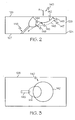
- FIG. 3 is a top view taken at A of FIG. 2 illustrating the structure of a percussion drilled shaped through hole
- FIGs. 4-6 illustrate steps in the method of forming a percussion drilled shaped through hole of FIGs. 1-3 .
- the description is explicitly directed toward percussion drilled shaped through holes formed in a combustor sidewall of a gas turbine engine, it should be appreciated that the shaped through holes and method of forming the shaped through holes can be used in any type of component where a through hole is desired to enable the passage of a fluid through a component, including those known now or hereafter in the art.
- FIG. 1 an exemplary embodiment of a portion of a turbofan gas turbine jet engine 100 is depicted and includes a compressor section 104, a combustion section 106, a turbine section 108, and an exhaust section 110.
- a compressor section 104 a combustion section 106
- a turbine section 108 a turbine section 108
- an exhaust section 110 a portion of a turbofan gas turbine jet engine 100.
- FIG. 1 only half the structure is shown, it being substantially rotationally symmetric about a centerline and axis of rotation 101.
- an intake section draws air into the turbofan gas turbine jet engine 100 and accelerates it toward the compressor section 104.
- the compressor section 104 includes two compressors, an intermediate pressure compressor 120, and a high pressure compressor 122.
- the intermediate pressure compressor 120 raises the pressure of the air directed into it and directs the compressed air into the high pressure compressor 122.
- a high pressure impeller 143 compresses the air and directs the high pressure air into the combustion section 106.
- the combustion section 106 which includes a combustor 124
- the high pressure air is mixed with fuel and combusted.
- the combustor 124 receives the high pressure air from the compressor section 104 and mixes it with fuel to generate combusted air.
- the combusted air is then directed into the turbine section 108.
- a cooling air flow is provided, and will be referred to herein as a thin film cooling airflow 132.
- a thin film cooling airflow 132 As illustrated in FIG. 1 , to generate this thin film cooling airflow 132 a plurality of percussion drilled shaped through holes 125 are drilled in a sidewall 126 of the combustor 124. These through holes 125 provide an entrance for the thin film cooling airflow 132 and aid in reducing penetration and dilution of the thin film cooling airflow 132 into the hot gases 130.
- the thin film cooling airflow 132 forms a thin cooling film over an interior surface of the combustor 124.
- FIG. 2 illustrated is a cross-section taken through line 2-2 of FIG. 1 , illustrating the geometry of a single percussion drilled shaped through hole 140, of the plurality of percussion drilled shaped through holes 125.
- the percussion drilled shaped through hole 140 comprises a primary crater 142, a secondary crater 144 and a metering hole 146.
- the percussion drilled shaped through hole 140 provides communication between an internal surface 127 and an external surface 128 of the sidewall 126 of the combustor 124.
- the percussion drilled shaped through holes 125 may provide communication between any two surfaces of a solid wall of a component.
- the primary crater 142 is initially formed in the external surface 128 to create a shallow non-perforating crater.
- the secondary crater 144 is formed to create a deeper non-perforating crater of a smaller diameter than the primary crater 142.
- the metering hole 146 provides for metering of the flow of thin film cooling air 132 passing through.
- the primary crater 142, the secondary crater 144 and the metering hole 146 are shaped to provide for the flow of thin film cooling air 132 according to the Coand effect, as generally illustrated by arrow 148.
- the Coand effect also known as boundary layer attachment, causes the thin film cooling air 132 to stay attached to a concave surface 149 such as that created by the primary crater 142 and the secondary crater 144, rather than follow a straight line in its original direction such as has been previously done in the art.
- the primary crater 142 and the secondary crater 144 form a diffusion section 145 resulting in a diffused flow of the thin film cooling air 132.
- the diffusion section 145 is curved in a manner to form a Coand ramp147 and enable the diffused flow of the thin film cooling air 132 to attach to the component sidewall via the Coand effect.
- through hole 140 is described herein as being comprised of the primary crater 142, the secondary crater 144 and the metering hole 146, in an alternative embodiment additional craters of diminishing size may be formed to create a gradual ramp suitable for attachment of the flow via the Coand effect.
- FIG. 3 illustrates a view along the bore of the percussion drilled shaped through hole 140 and provides further illustration of the geometry of each of the percussion drilled shaped through holes 125.
- the primary crater 142 provides an entrance through the external surface 128 of the sidewall 126 for a cooling fluid, and more particularly thin film cooling air 132.
- the primary crater 142 is formed generally circular in shape, but is not limited to being circular and may take on other shapes, such as oval, rectangular, or the like.
- the secondary crater 144 is formed offset from a centerline of the primary crater 142 and is smaller in size and shape.
- the metering hole 146 may be formed generally offset from a centerline of the secondary crater 144 and provides an exit for the cooling fluid, and more particularly thin film cooling air 132, through the internal surface 127 of the sidewall 126. It should be understood that the terms internal, external, entrance and exit are being used herein to describe directional information, but could be used interchangeably depending on the embodiment being described and the cooling fluid passing through.
- the percussion drilled shaped through hole 140, and more particularly the primary crater 142, the secondary crater 144, and the metering hole 146 are formed using conventional laser percussion drilling as illustrated in FIGs. 4-6 .
- a broad high pulse or series of pulses, using a highly defocused pulsed laser beam 150 is directed to the component sidewall 126.
- the use of a defocused pulsed laser beam 150 provides control of the area of the component sidewall 126 that is struck by the coherent radiation of the laser 150.
- the pulsed laser beam 150 delivers the pulses in a direction substantially normal to the component sidewall 126. As shown in FIG.
- the energy of the pulsed laser beam 150 ablates material from the component sidewall 126 such that a crater begins to form.
- the crater becomes progressively deeper with each pulse to form a shallow non-perforating crater, and more particularly the primary crater 142.
- the pulses from the pulsed laser beam 150 may be arranged in a pattern such as to form a substantially elliptical shape, which is repeated until the primary crater 142 is formed.
- Optimum drilling conditions are achieved by controlling the duration of the pulses, the pauses between pulses, the pulse energy and beam orientation relative to the surface of the part.
- a second potentially lower energy pulse or series of pulses using a pulsed laser beam 152 having a focus closer than that of the pulsed laser beam 150, is directed to the component sidewall 126.
- the pulsed laser beam 152 delivers the pulse or pulses at a shallower angle to the component sidewall 126 than the highly defocused laser beam 150.
- the second pulse, or series of pulses is applied slightly upstream and at an angle of approximately 60°, normal to the component sidewall 126 to form the secondary crater 144 of a smaller diameter than the primary crater 142. As shown in FIG.
- the energy of the laser beam 152 ablates material from the component sidewall 126 such that a crater begins to form.
- the crater becomes progressively deeper with each pulse to form a shallow non-perforating crater, and more particularly the secondary crater 144.
- By controlling the energy of the laser pulses and controlling the number of pulses delivered the secondary crater 144 is drilled to a predetermined depth.
- FIG. 6 illustrates a further step where the metering hole 146 is formed and provides for the flow of the thin film cooling air 132 ( FIG. 1 ) through the component sidewall 126.
- a final pulse or series of pulses using a pulsed laser beam 154 is directed to the component sidewall 126.
- the pulsed laser beam 154 may deliver the pulse or pulses at a shallower angle to the component sidewall 126 than the previous laser beam 152.
- the final pulse, or series of pulses is applied at a substantially shallow angle, normal to the component sidewall 126 to break through the surface 127 and form the metering hole 146. As shown in FIG.
- the energy of the beam 154 ablates material from the component sidewall 126 such that a long hole having a diameter less than the previously formed craters 142 and 144 is formed.
- the metering hole 146 controls the flow of fluid through the percussion drilled shaped through hole 140.
- any remaining ridges formed by the primary crater 142, the secondary crater 144 and the metering hole 146 are removed by laser drilling to create a proper Coand ramp.
- a percussion drilled shaped through hole and a method of forming the shaped through hole wherein the exiting thin film cooling air 132 will have a low normal velocity relative to the component sidewall 126.
- the diffusing section 145 of the shaped through hole 140 causes the diffused flow of thin film cooling air 132 to attach to the component sidewall 126 using the Coand effect.
- the geometry of the shaped through hole 140 can be produced economically by percussion drilling via laser or any other energetic beam machining method.
Landscapes
- Engineering & Computer Science (AREA)
- Mechanical Engineering (AREA)
- Physics & Mathematics (AREA)
- Optics & Photonics (AREA)
- Plasma & Fusion (AREA)
- General Engineering & Computer Science (AREA)
- Turbine Rotor Nozzle Sealing (AREA)
- Laser Beam Processing (AREA)
Claims (10)
- Komponente, die Folgendes umfasst:eine Konstruktion mit einer ersten Oberfläche (128) und einer zweiten Oberfläche (127); undmehrere Effusionskühllöcher (125), die sich zwischen der ersten und der zweiten Oberfläche erstrecken, wobei jedes Effusionskühlloch (140) Folgendes umfasst:einen primären Krater (142), der in der ersten Oberfläche (128) der Komponente ausgebildet ist, wobei der primäre Krater (142) eine konkave Oberfläche (149) definiert;einen sekundären Krater (144), der einen innerhalb des primären Kraters (142) ausgebildeten Einlass hat und im Wesentlichen von einer Mittellinie des primären Kraters (142) versetzt vorgesehen ist, wobei der sekundäre Krater (144) eine konkave Oberfläche (149) definiert; undein Dosierloch (146) mit einem innerhalb des sekundären Kraters (144) ausgebildeten Einlass, das sich durch die Komponente hin zur zweiten Oberfläche (127) erstreckt,wobei die konkave Oberfläche (149) des primären Kraters (142), die konkave Oberfläche (149) des sekundären Kraters (144) und das Dosierloch (146) einen Diffusionsbereich (145) definieren, der eine Coandä-Rampe oder Grenzflächenanhaftungsrampe bildet und bewirkt, dass Fluid durch das schlagbohrförmige Durchgangsloch (140) gemäß dem Coandä-Effekt oder dem Grenzflächenanhaftungseffekt strömen kann.
- Komponente nach Anspruch 1, bei der der primäre Krater (142) im Wesentlichen elliptisch geformt ist.
- Komponente nach Anspruch 1, bei der der sekundäre Krater (144) im Wesentlichen elliptisch geformt ist.
- Komponente nach Anspruch 1, bei der der primäre Krater (142) ein flacher, nicht durchgehender Krater ist.
- Komponente nach Anspruch 4, bei der der sekundäre Krater (144) ein nicht durchgehender Krater ist, der eine Tiefe hat, die größer als eine Tiefe des primären Kraters (142) ist, und der einen Durchmesser hat, der kleiner als ein Durchmesser des primären Kraters (142) ist.
- Verfahren zur Herstellung eines geformten Durchgangslochs (140) in einer Komponente zwischen einer ersten Oberfläche (128) und einer zweiten Oberfläche (127) davon, wobei das Verfahren die folgenden Schritte umfasst:Laserschlagbohren eines primären Kraters (142) in der ersten Oberfläche (128) der Komponente, wobei der primäre Krater (142) eine Mittellinie beinhaltet und eine konvexe Oberfläche (149) definiert;Laserschlagbohren eines sekundären Kraters (144) mit einem Einlass innerhalb des primären Kraters (142), wobei der sekundäre Krater (144) im Wesentlichen von der Mittellinie des primären Kraters (142) versetzt vorgesehen ist und eine konvexe Oberfläche (149) definiert; undLaserschlagbohren eines Dosierlochs (146) mit einem Einlass innerhalb des sekundären Kraters (144), das sich durch die Komponente hin zur zweiten Oberfläche (127) erstreckt,wobei die konvexe Oberfläche (149) des primären Kraters (142), die konvexe Oberfläche (149) des sekundären Kraters (144) und das Dosierloch (146) einen Diffusionsbereich (145) definieren, der eine Coandä-Rampe oder Grenzflächenanhaftungsrampe bildet und bewirkt, dass Fluid gemäß dem Coandä-Effekt oder dem Grenzflächenanhaftungseffekt durchströmen kann.
- Verfahren zur Herstellung eines geformten Durchgangslochs (140) nach Anspruch 6, bei dem der Schritt des Laserschlagbohrens eines primären Kraters (142) das Bohren in einer senkrecht zur ersten Oberfläche (128) verlaufenden Richtung beinhaltet.
- Verfahren zur Herstellung eines geformten Durchgangslochs (140) nach Anspruch 6, bei dem der Schritt des per Laser (150) durchgeführten Schlagbohrens eines primären Kraters (142) und eines sekundären Kraters (144) das in die Komponente erfolgende Bohren unter Verwendung eines einzelnen defokussierten Impulses beinhaltet.
- Verfahren zur Herstellung eines geformten Durchgangslochs (140) nach Anspruch 6, bei dem der Schritt des Laserschlagbohrens eines primären Kraters (142) und eines sekundären Kraters (144) das in die Komponente erfolgende Bohren unter Verwendung einer Reihe defokussierter Impulse beinhaltet.
- Verfahren zur Herstellung eines geformten Durchgangslochs (140) nach Anspruch 6, bei dem der Schritt des Laserschlagbohrens eines sekundären Kraters (144) das Bohren eines nicht durchgehenden Kraters beinhaltet, der von der Mittellinie des primären Kraters (142) versetzt vorgesehen ist und einen Durchmesser hat, der kleiner als ein Durchmesser des primären Kraters (142) ist.
Applications Claiming Priority (1)
| Application Number | Priority Date | Filing Date | Title |
|---|---|---|---|
| US11/841,261 US7820267B2 (en) | 2007-08-20 | 2007-08-20 | Percussion drilled shaped through hole and method of forming |
Publications (2)
| Publication Number | Publication Date |
|---|---|
| EP2027963A1 EP2027963A1 (de) | 2009-02-25 |
| EP2027963B1 true EP2027963B1 (de) | 2010-11-17 |
Family
ID=40011625
Family Applications (1)
| Application Number | Title | Priority Date | Filing Date |
|---|---|---|---|
| EP08162416A Not-in-force EP2027963B1 (de) | 2007-08-20 | 2008-08-14 | Komponent mit einem schlagbohrförmigen Durchgangsloch mit Coanda-Effekt und Verfahren zur herstellung dieses Loches unter Verwendung vom Schlagbohrlaserverfahren |
Country Status (4)
| Country | Link |
|---|---|
| US (1) | US7820267B2 (de) |
| EP (1) | EP2027963B1 (de) |
| CA (1) | CA2638880A1 (de) |
| DE (1) | DE602008003492D1 (de) |
Families Citing this family (40)
| Publication number | Priority date | Publication date | Assignee | Title |
|---|---|---|---|---|
| DE102009007164A1 (de) * | 2009-02-03 | 2010-08-12 | Rolls-Royce Deutschland Ltd & Co Kg | Verfahren zum Ausbilden einer Kühlluftöffnung in einer Wand einer Gasturbinenbrennkammer sowie nach dem Verfahren hergestellte Brennkammerwand |
| US9434025B2 (en) | 2011-07-19 | 2016-09-06 | Pratt & Whitney Canada Corp. | Laser drilling methods of shallow-angled holes |
| US8631557B2 (en) | 2011-07-19 | 2014-01-21 | Pratt & Whitney Canada Corp. | Laser drilling methods of shallow-angled holes |
| US8624151B2 (en) | 2011-07-19 | 2014-01-07 | Pratt & Whitney Canada Corp. | Laser drilling methods of shallow-angled holes |
| US8915713B2 (en) * | 2011-09-27 | 2014-12-23 | General Electric Company | Offset counterbore for airfoil cooling hole |
| EP2604866B1 (de) | 2011-12-13 | 2016-11-30 | MTU Aero Engines GmbH | Verfahren und System zur Reduzierung von Strömungsverlusten sowie Strömungsmaschine |
| JP2014066224A (ja) * | 2012-09-27 | 2014-04-17 | Hitachi Ltd | ガスタービン翼 |
| US10113433B2 (en) | 2012-10-04 | 2018-10-30 | Honeywell International Inc. | Gas turbine engine components with lateral and forward sweep film cooling holes |
| EP2964891B1 (de) | 2013-03-05 | 2019-06-12 | Rolls-Royce North American Technologies, Inc. | Komponentenanordnung eines gasturbinenmotors |
| US9874110B2 (en) | 2013-03-07 | 2018-01-23 | Rolls-Royce North American Technologies Inc. | Cooled gas turbine engine component |
| DE102013210857B3 (de) * | 2013-06-11 | 2014-08-21 | Trumpf Werkzeugmaschinen Gmbh + Co. Kg | Verfahren zum Einstechen in metallische Werkstücke mittels eines Laserstrahls |
| WO2015002686A2 (en) * | 2013-06-14 | 2015-01-08 | United Technologies Corporation | Gas turbine engine combustor liner panel |
| WO2015050592A2 (en) * | 2013-06-14 | 2015-04-09 | United Technologies Corporation | Gas turbine engine combustor liner panel |
| DE102013214487A1 (de) | 2013-07-24 | 2015-01-29 | Rolls-Royce Deutschland Ltd & Co Kg | Brennkammerschindel einer Gasturbine |
| WO2015077755A1 (en) * | 2013-11-25 | 2015-05-28 | United Technologies Corporation | Film cooled multi-walled structure with one or more indentations |
| US10030524B2 (en) | 2013-12-20 | 2018-07-24 | Rolls-Royce Corporation | Machined film holes |
| US9931814B2 (en) | 2014-09-25 | 2018-04-03 | General Electric Company | Article and method for making an article |
| US9931695B2 (en) | 2014-09-25 | 2018-04-03 | General Electric Company | Article and method for making an article |
| US10077903B2 (en) | 2014-10-20 | 2018-09-18 | United Technologies Corporation | Hybrid through holes and angled holes for combustor grommet cooling |
| EP3034803A1 (de) | 2014-12-16 | 2016-06-22 | Rolls-Royce Corporation | Hängersystem für eine turbinenmotorkomponente |
| US9757936B2 (en) | 2014-12-29 | 2017-09-12 | General Electric Company | Hot gas path component |
| US9611824B2 (en) * | 2015-02-18 | 2017-04-04 | Caterpillar Inc. | Process for manufacturing an injector body |
| US10871075B2 (en) | 2015-10-27 | 2020-12-22 | Pratt & Whitney Canada Corp. | Cooling passages in a turbine component |
| US10533749B2 (en) | 2015-10-27 | 2020-01-14 | Pratt & Whitney Cananda Corp. | Effusion cooling holes |
| EP3179040B1 (de) | 2015-11-20 | 2021-07-14 | Raytheon Technologies Corporation | Bauteil für ein gasturbinentriebwerk und zugehöriges verfahren zur herstellung eines filmgekühltes artikels |
| US20170306764A1 (en) | 2016-04-26 | 2017-10-26 | General Electric Company | Airfoil for a turbine engine |
| US11021965B2 (en) | 2016-05-19 | 2021-06-01 | Honeywell International Inc. | Engine components with cooling holes having tailored metering and diffuser portions |
| DE102018113508A1 (de) * | 2018-06-06 | 2019-12-12 | Liebherr-Components Deggendorf Gmbh | Verfahren zum Fertigen einer Düse |
| US10822958B2 (en) | 2019-01-16 | 2020-11-03 | General Electric Company | Component for a turbine engine with a cooling hole |
| US11306659B2 (en) * | 2019-05-28 | 2022-04-19 | Honeywell International Inc. | Plug resistant effusion holes for gas turbine engine |
| CN112282857B (zh) * | 2020-10-26 | 2021-09-28 | 上海交通大学 | 一种气膜冷却孔型结构 |
| US12123839B2 (en) | 2021-08-13 | 2024-10-22 | Rtx Corporation | Forming and/or inspecting cooling aperture(s) in a turbine engine component |
| US11673200B2 (en) | 2021-08-13 | 2023-06-13 | Raytheon Technologies Corporation | Forming cooling aperture(s) using electrical discharge machining |
| US11813706B2 (en) | 2021-08-13 | 2023-11-14 | Rtx Corporation | Methods for forming cooling apertures in a turbine engine component |
| US11898465B2 (en) | 2021-08-13 | 2024-02-13 | Rtx Corporation | Forming lined cooling aperture(s) in a turbine engine component |
| US11732590B2 (en) | 2021-08-13 | 2023-08-22 | Raytheon Technologies Corporation | Transition section for accommodating mismatch between other sections of a cooling aperture in a turbine engine component |
| US11913119B2 (en) | 2021-08-13 | 2024-02-27 | Rtx Corporation | Forming cooling aperture(s) in a turbine engine component |
| US11542831B1 (en) | 2021-08-13 | 2023-01-03 | Raytheon Technologies Corporation | Energy beam positioning during formation of a cooling aperture |
| US11603769B2 (en) | 2021-08-13 | 2023-03-14 | Raytheon Technologies Corporation | Forming lined cooling aperture(s) in a turbine engine component |
| US20240293892A1 (en) * | 2023-03-05 | 2024-09-05 | Raytheon Technologies Corporation | Forming cooling aperture(s) in a turbine engine component |
Family Cites Families (35)
| Publication number | Priority date | Publication date | Assignee | Title |
|---|---|---|---|---|
| US3698834A (en) * | 1969-11-24 | 1972-10-17 | Gen Motors Corp | Transpiration cooling |
| US3700418A (en) * | 1969-11-24 | 1972-10-24 | Gen Motors Corp | Cooled airfoil and method of making it |
| US4672727A (en) | 1985-12-23 | 1987-06-16 | United Technologies Corporation | Method of fabricating film cooling slot in a hollow airfoil |
| US4738588A (en) * | 1985-12-23 | 1988-04-19 | Field Robert E | Film cooling passages with step diffuser |
| US4684323A (en) * | 1985-12-23 | 1987-08-04 | United Technologies Corporation | Film cooling passages with curved corners |
| US4819325A (en) * | 1987-06-01 | 1989-04-11 | Technical Manufacturing Systems, Inc. | Method of forming electro-discharge machining electrode |
| US4923371A (en) * | 1988-04-01 | 1990-05-08 | General Electric Company | Wall having cooling passage |
| DE3934587C2 (de) * | 1989-10-17 | 1998-11-19 | Bosch Gmbh Robert | Verfahren zum Herstellen von mittels Laserstrahlung erzeugter, hochpräziser Durchgangsbohrungen in Werkstücken |
| US5405242A (en) * | 1990-07-09 | 1995-04-11 | United Technologies Corporation | Cooled vane |
| US6744010B1 (en) | 1991-08-22 | 2004-06-01 | United Technologies Corporation | Laser drilled holes for film cooling |
| US5683600A (en) | 1993-03-17 | 1997-11-04 | General Electric Company | Gas turbine engine component with compound cooling holes and method for making the same |
| US5747769A (en) | 1995-11-13 | 1998-05-05 | General Electric Company | Method of laser forming a slot |
| US5609779A (en) * | 1996-05-15 | 1997-03-11 | General Electric Company | Laser drilling of non-circular apertures |
| JPH106059A (ja) | 1996-06-25 | 1998-01-13 | Mitsubishi Heavy Ind Ltd | シェイプド冷却穴加工方法 |
| US6383602B1 (en) * | 1996-12-23 | 2002-05-07 | General Electric Company | Method for improving the cooling effectiveness of a gaseous coolant stream which flows through a substrate, and related articles of manufacture |
| US6624382B2 (en) | 1997-01-30 | 2003-09-23 | Anvik Corporation | Configured-hole high-speed drilling system for micro-via pattern formation, and resulting structure |
| US6004100A (en) * | 1997-11-13 | 1999-12-21 | United Technologies Corporation | Trailing edge cooling apparatus for a gas turbine airfoil |
| EP0950463B1 (de) | 1998-03-23 | 2002-01-23 | Alstom | Nichtkreisförmige Kühlbohrung und Verfahren zur Herstellung derselben |
| GB9821639D0 (en) | 1998-10-06 | 1998-11-25 | Rolls Royce Plc | Coolant passages for gas turbine components |
| JP2000141069A (ja) | 1998-11-10 | 2000-05-23 | Toshiba Corp | タービン翼およびその冷却孔加工方法 |
| DE19960797C1 (de) | 1999-12-16 | 2001-09-13 | Mtu Aero Engines Gmbh | Verfahren zum Herstellen einer Öffnung in einem metallischen Bauteil |
| US6573474B1 (en) | 2000-10-18 | 2003-06-03 | Chromalloy Gas Turbine Corporation | Process for drilling holes through a thermal barrier coating |
| US6420677B1 (en) | 2000-12-20 | 2002-07-16 | Chromalloy Gas Turbine Corporation | Laser machining cooling holes in gas turbine components |
| US6504274B2 (en) * | 2001-01-04 | 2003-01-07 | General Electric Company | Generator stator cooling design with concavity surfaces |
| US6603095B2 (en) | 2001-07-23 | 2003-08-05 | Siemens Automotive Corporation | Apparatus and method of overlapping formation of chamfers and orifices by laser light |
| DE10143153A1 (de) * | 2001-09-03 | 2003-03-20 | Rolls Royce Deutschland | Turbinenschaufel für eine Gasturbine mit zumindest einer Kühlungsausnehmung |
| US6599088B2 (en) | 2001-09-27 | 2003-07-29 | Borgwarner, Inc. | Dynamically sealing ring fan shroud assembly |
| GB2383769B (en) | 2001-10-06 | 2004-10-13 | Rolls Royce Plc | Method of laser drilling a hole |
| GB2381489B (en) | 2001-10-30 | 2004-11-17 | Rolls Royce Plc | Method of forming a shaped hole |
| US6918742B2 (en) * | 2002-09-05 | 2005-07-19 | Siemens Westinghouse Power Corporation | Combustion turbine with airfoil having multi-section diffusion cooling holes and methods of making same |
| GB2395157B (en) | 2002-11-15 | 2005-09-07 | Rolls Royce Plc | Laser driliing shaped holes |
| US6897401B2 (en) * | 2003-07-31 | 2005-05-24 | United Technologies Corporation | Non-separating diffuser for holes produced by a two step process |
| US7816625B2 (en) | 2003-10-06 | 2010-10-19 | Siemens Aktiengesellschaft | Method for the production of a hole and device |
| US7246999B2 (en) * | 2004-10-06 | 2007-07-24 | General Electric Company | Stepped outlet turbine airfoil |
| US7186085B2 (en) * | 2004-11-18 | 2007-03-06 | General Electric Company | Multiform film cooling holes |
-
2007
- 2007-08-20 US US11/841,261 patent/US7820267B2/en not_active Expired - Fee Related
-
2008
- 2008-08-14 DE DE602008003492T patent/DE602008003492D1/de active Active
- 2008-08-14 EP EP08162416A patent/EP2027963B1/de not_active Not-in-force
- 2008-08-19 CA CA002638880A patent/CA2638880A1/en not_active Abandoned
Also Published As
| Publication number | Publication date |
|---|---|
| DE602008003492D1 (de) | 2010-12-30 |
| US7820267B2 (en) | 2010-10-26 |
| EP2027963A1 (de) | 2009-02-25 |
| CA2638880A1 (en) | 2009-02-20 |
| US20090053464A1 (en) | 2009-02-26 |
Similar Documents
| Publication | Publication Date | Title |
|---|---|---|
| EP2027963B1 (de) | Komponent mit einem schlagbohrförmigen Durchgangsloch mit Coanda-Effekt und Verfahren zur herstellung dieses Loches unter Verwendung vom Schlagbohrlaserverfahren | |
| CA2436912C (en) | Laser machining cooling holes in gas turbine components | |
| US5458461A (en) | Film cooled slotted wall | |
| EP3269930B1 (de) | Bauteil eines gasturbinentriebwerk und zugehörige herstellungsverfahren | |
| US6307175B1 (en) | Method of producing a noncircular cooling bore | |
| US20090169394A1 (en) | Method of forming cooling holes and turbine airfoil with hybrid-formed cooling holes | |
| US6781091B2 (en) | Method of forming a shaped hole | |
| EP2138675A2 (de) | Rotorschaufel | |
| US10280763B2 (en) | Airfoil cooling passageways for generating improved protective film | |
| US11773729B2 (en) | Component for a gas turbine engine with a film hole | |
| US10024169B2 (en) | Engine component | |
| EP3070406A1 (de) | Motorbauteil | |
| JP2008510955A (ja) | 熱保護体のない燃焼器および燃焼器ライナの冷却 | |
| JP2002364305A (ja) | タービンエンジン用の冷却可能なブレードまたはベーン | |
| JP2016166607A (ja) | エンジン構成要素 | |
| EP1790822B1 (de) | Kühlung mit Mikrokanälen für Turbinenschaufeln | |
| JP2018031370A (ja) | インピンジメント冷却のための外壁凹部を有する部品 | |
| CA2613781A1 (en) | Method for preventing backflow and forming a cooling layer in an airfoil | |
| EP3494344B1 (de) | Maschinenteil, insbesondere eine turbomaschinenkomponente mit kühlenden eigenschaften | |
| EP3450684A1 (de) | Verfahren zur herstellung einer komponente | |
| GB2506092A (en) | Turbine airfoil suction aided film cooling means |
Legal Events
| Date | Code | Title | Description |
|---|---|---|---|
| PUAI | Public reference made under article 153(3) epc to a published international application that has entered the european phase |
Free format text: ORIGINAL CODE: 0009012 |
|
| 17P | Request for examination filed |
Effective date: 20080814 |
|
| AK | Designated contracting states |
Kind code of ref document: A1 Designated state(s): AT BE BG CH CY CZ DE DK EE ES FI FR GB GR HR HU IE IS IT LI LT LU LV MC MT NL NO PL PT RO SE SI SK TR |
|
| AX | Request for extension of the european patent |
Extension state: AL BA MK RS |
|
| 17Q | First examination report despatched |
Effective date: 20090401 |
|
| AKX | Designation fees paid |
Designated state(s): DE FR |
|
| GRAP | Despatch of communication of intention to grant a patent |
Free format text: ORIGINAL CODE: EPIDOSNIGR1 |
|
| GRAS | Grant fee paid |
Free format text: ORIGINAL CODE: EPIDOSNIGR3 |
|
| GRAA | (expected) grant |
Free format text: ORIGINAL CODE: 0009210 |
|
| AK | Designated contracting states |
Kind code of ref document: B1 Designated state(s): DE FR |
|
| REF | Corresponds to: |
Ref document number: 602008003492 Country of ref document: DE Date of ref document: 20101230 Kind code of ref document: P |
|
| PLBE | No opposition filed within time limit |
Free format text: ORIGINAL CODE: 0009261 |
|
| STAA | Information on the status of an ep patent application or granted ep patent |
Free format text: STATUS: NO OPPOSITION FILED WITHIN TIME LIMIT |
|
| 26N | No opposition filed |
Effective date: 20110818 |
|
| PGFP | Annual fee paid to national office [announced via postgrant information from national office to epo] |
Ref country code: FR Payment date: 20110811 Year of fee payment: 4 |
|
| REG | Reference to a national code |
Ref country code: DE Ref legal event code: R097 Ref document number: 602008003492 Country of ref document: DE Effective date: 20110818 |
|
| REG | Reference to a national code |
Ref country code: FR Ref legal event code: ST Effective date: 20130430 |
|
| PG25 | Lapsed in a contracting state [announced via postgrant information from national office to epo] |
Ref country code: FR Free format text: LAPSE BECAUSE OF NON-PAYMENT OF DUE FEES Effective date: 20120831 |
|
| PGFP | Annual fee paid to national office [announced via postgrant information from national office to epo] |
Ref country code: DE Payment date: 20171030 Year of fee payment: 10 |
|
| REG | Reference to a national code |
Ref country code: DE Ref legal event code: R119 Ref document number: 602008003492 Country of ref document: DE |
|
| PG25 | Lapsed in a contracting state [announced via postgrant information from national office to epo] |
Ref country code: DE Free format text: LAPSE BECAUSE OF NON-PAYMENT OF DUE FEES Effective date: 20190301 |
|
| P01 | Opt-out of the competence of the unified patent court (upc) registered |
Effective date: 20230525 |