EP2028026A2 - Reifenparameterüberwachungssystem mit Magnetfeldsensor - Google Patents
Reifenparameterüberwachungssystem mit Magnetfeldsensor Download PDFInfo
- Publication number
- EP2028026A2 EP2028026A2 EP08252489A EP08252489A EP2028026A2 EP 2028026 A2 EP2028026 A2 EP 2028026A2 EP 08252489 A EP08252489 A EP 08252489A EP 08252489 A EP08252489 A EP 08252489A EP 2028026 A2 EP2028026 A2 EP 2028026A2
- Authority
- EP
- European Patent Office
- Prior art keywords
- tire
- location
- signals
- sensor unit
- signal
- Prior art date
- Legal status (The legal status is an assumption and is not a legal conclusion. Google has not performed a legal analysis and makes no representation as to the accuracy of the status listed.)
- Withdrawn
Links
Images




Classifications
-
- B—PERFORMING OPERATIONS; TRANSPORTING
- B60—VEHICLES IN GENERAL
- B60C—VEHICLE TYRES; TYRE INFLATION; TYRE CHANGING; CONNECTING VALVES TO INFLATABLE ELASTIC BODIES IN GENERAL; DEVICES OR ARRANGEMENTS RELATED TO TYRES
- B60C23/00—Devices for measuring, signalling, controlling, or distributing tyre pressure or temperature, specially adapted for mounting on vehicles; Arrangement of tyre inflating devices on vehicles, e.g. of pumps or of tanks; Tyre cooling arrangements
- B60C23/02—Signalling devices actuated by tyre pressure
- B60C23/04—Signalling devices actuated by tyre pressure mounted on the wheel or tyre
- B60C23/0408—Signalling devices actuated by tyre pressure mounted on the wheel or tyre transmitting the signals by non-mechanical means from the wheel or tyre to a vehicle body mounted receiver
- B60C23/0415—Automatically identifying wheel mounted units, e.g. after replacement or exchange of wheels
- B60C23/0416—Automatically identifying wheel mounted units, e.g. after replacement or exchange of wheels allocating a corresponding wheel position on vehicle, e.g. front/left or rear/right
Definitions
- This invention relates to vehicle tire parameter monitoring systems. More particularly, this invention relates to a tire parameter monitoring system having a sensor unit position location feature using permanent magnets.
- Tire parameter monitoring systems are known and are commonly used to monitor one or more parameters of interest in individual pneumatic tires of a vehicle and to provide an advisory signal to the driver, usually via an on-board computer system, containing information about the tire parameter(s).
- the portion of the tire parameter monitoring system located at or in the individual tires is termed the sensor unit, and is coupled to one or more sensors capable of measuring the parameter(s) of interest and generating an electrical signal representative of the value of the measurement, a signal generator (typically an r.f. signal generator) capable of generating a wireless signal corresponding to the electrical signal, a microcontroller (such as a microprocessor or a digital signal processor) and a power source.
- a tire parameter sensor system which monitors internal tire pressure is disclosed in commonly assigned, U.S. Patent number 6,959,594 issued November 1, 2005 for “External Mount Tire Pressure Sensor System”, the disclosure of which is hereby incorporated by reference.
- a tire pressure monitoring system which incorporates a power saving unit providing extended useful battery life is disclosed in commonly assigned, U.S. Patent number 7,222,523 issued May 29, 2007 for "Tire Pressure Sensor System With Improved Sensitivity And Power Saving", the disclosure of which is hereby incorporated by reference.
- the advisory signal produced by the sensor unit may indicate (a) whether a given parameter in the associated vehicle tire has a current value lying within or outside of a predetermined safe range, (b) the measured value of the parameter, or (c) some other tire parameter information of interest.
- Examples of common tire parameters are internal tire pressure, tire temperature, internal tire air temperature, and lateral tire force.
- the parameter may be related to the condition of the wheel on which the tire is mounted, such as the angular moment of the wheel, concentricity or the like.
- the advisory signal is typically generated by the r.f. signal generator controlled by the microprocessor connected to the tire parameter sensor, the advisory signal being generated in accordance with the system design characteristics: i.e., whether the system uses the range indicator value (in range/outside range), the measured value, or the other information of interest.
- This r.f. signal is transmitted to a vehicle-mounted receiver, which uses the advisory signal to alert the driver either visually (by activating a warning lamp or display) or audibly (by activating an audible alarm) or both.
- the receiver may use the advisory signal for some other system purpose, such as to activate a vehicle control system, such as braking control, suspension control, and the like; to store the parameter data for future analysis; or for any other desired purpose.
- the identification signal is unique to the sensor unit which generates the parameter condition. This unique identification signal is initially correlated to tire location on the vehicle by a technician having the required skill and training to operate the system in an initial training mode. Once each sensor unit has been initially correlated to its physical location on the vehicle, any advisory signal generated by a given sensor unit and received by the vehicle-mounted receiver can be uniquely identified with the location of the tire whose parameter condition is specified by the advisory signal.
- a disadvantage with this type of location correlation technique is that any change to the original tire and sensor unit location requires that the system be re-correlated. For example, if the vehicle tires are relocated to different positions in the normal course of vehicle servicing, the physical locations of the sensor units will change if the sensor units are fixed to the tires or the wheels on which the tires are mounted (which is typical), and each individual sensor unit must be re-correlated to the physical location of the associated tire. The same is true (a) when a spare tire is exchanged for a flat tire on the vehicle; (b) when one or more new tires are installed on the vehicle wheels and mounted on the vehicle; and (c) when a new sensor unit is installed in place of a unit which stops functioning properly.
- re-correlation requires the efforts of someone having the required skill and training to operate the system in a training mode. While some vehicle owners may be capable of acquiring the necessary skill and training, others may not. The latter will necessarily suffer delay and expense when re-configuring the vehicle tires and wheels; the former will suffer at least the delay attendant upon re-familiarizing oneself with the steps required to re-program an electronic system.
- a variation of this type of sensor unit correlation system uses a manually actuatable transmitter installed in the valve stem of a tire.
- the transmitter is actuated by inserting a small object into the valve stem a sufficient axial distance to operate a switch, which causes the transmitter to send an appropriate signal to a vehicle-mounted receiver capable of correlating the signal from the operating transmitter to the tire to which the transmitter is attached.
- a switch which causes the transmitter to send an appropriate signal to a vehicle-mounted receiver capable of correlating the signal from the operating transmitter to the tire to which the transmitter is attached.
- Another common technique used to correlate the advisory signals received by the vehicle-mounted receiver with the physical location on the vehicle of the tire whose parameter condition is specified by a given advisory signal incorporates a special multiple antenna interrogator system connected to a vehicle-mounted controller and a complementary set of sensor units. Each antenna is connected to the controller in such a way that only one antenna is actively coupled to the controller during any given interrogation interval. Each antenna is located adjacent a different associated one of the sensor units in sufficiently close proximity that an interrogation signal generated by a given antenna is operatively coupled essentially only to the associated sensor unit.
- Each sensor unit has a circuit responsive to an interrogation signal from the associated antenna to initiate a parameter signal transmission sequence during which the value measured by a sensor is transmitted to a receiver located in the vehicle-mounted controller, where it is processed. Since the location of each individual interrogation antenna is fixed, it can be permanently correlated to a wheel location. Therefore, when the controller activates a given interrogation antenna, the subsequently received parameter signal is automatically correlated with the correct tire location. Examples of this type of unit are disclosed in U.S. Patent Application Publication No. US 2003/0145650 A1 published August 7, 2003 ; and U.S. Patent No. 6,838,985 B2 , the disclosures of which are hereby incorporated by reference.
- a disadvantage to the interrogator antenna system described above lies in the requirement for the installation of the separate interrogation antennae adjacent the tire parameter sensor units.
- the necessary electrical cabling must be routed between the controller and the individual antennae. This imposes a requirement of careful routing of the cables to avoid mechanical abrasion, electrical interference, and thermal stresses over time. As a consequence, installation cost and hardware durability are factors of concern when deciding to implement such a system.
- the invention comprises a method and system for providing sensor unit location information which is simple and inexpensive to implement, highly reliable, and accurate.
- the invention comprises a sensor unit for use with a vehicle mounted tire parameter monitoring system having at least one tire parameter sensor, the sensor unit including a magnetic sensing element for generating location signals from magnetic fields encountered by the magnetic sensing element; a microcontroller coupled to the magnetic sensing element for receiving and processing the location signals and tire parameter signals from an associated tire parameter sensor; and a signal generator controlled by the microcontroller for transmitting the processed location signals and the tire parameter signals to a receiving location.
- the magnetic sensing element of the sensor unit preferably comprises an inductive coil having an output coupled to an input of the microcontroller.
- the sensor unit further preferably includes an analog-to-digital converter having an input coupled to the magnetic sensing element and an output coupled to the microcontroller for converting the analog location signals to digital form.
- the sensor unit further includes one or more tire parameter sensors each having an output coupled to the microcontroller for supplying current values of the monitored tire parameters for processing by the microcontroller.
- the invention comprises a tire parameter monitoring system for monitoring the current values of tire parameters of tires mounted on a vehicle, the system comprising a plurality of sensor units each associated to a different tire on the vehicle, each sensor unit including a magnetic sensing element for generating location signals from magnetic fields encountered by the magnetic sensing element; a microcontroller coupled to the magnetic sensing element for receiving and processing the location signals and tire parameter signals from an associated tire parameter sensor; and a signal generator controlled by the microcontroller for transmitting the processed location signals and the tire parameter signals to a receiving location; and a plurality of sets of magnets for generating a plurality of different magnetic field signals, each set of magnets being located in proximity to a different one of the plurality of sensor units in a location at which the magnetic field generated thereby is encountered by the corresponding sensor unit as the associated tire rotates.
- Each magnetic sensing element preferably comprises an inductive coil.
- Each sensor unit preferably includes an analog-to-digital converter having an input coupled to the magnetic sensing element and an output coupled to the microcontroller for converting analog location signals to digital form.
- Each said sensor unit further preferably includes one or more tire parameter sensors each having an output coupled to the microcontroller for supplying current values of the monitored tire parameters for processing by the microcontroller.
- the system further includes a receiver processor for receiving and processing the location signals and tire parameter signals from the sensor units.
- the invention comprises a method of correlating tire parameter signals generated by sensor units associated to different ones of a plurality of tires on a vehicle with the location of tires whose parameters are monitored by the sensor units, the method comprising the steps of:
- Step (a) of generating preferably includes the step of using a plurality of sets of permanent magnets, each set being located in proximity to a different tire.
- Step (b) of converting preferably includes the steps of moving a magnetic sensing element located on a given sensor unit through the proximate magnetic field signal.
- Each electric sensor unit location signal is preferably an analog signal; and step (b) of converting preferably includes the step of converting the analog signal to a digital signal.
- the method further preferably includes the step (e) of processing the signals transmitted in step (d) at the receiving location, and the step (e) of processing preferably includes the step of generating a driver advisory signal for a given tire parameter.
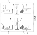
- Fig. 1 is a schematic top plan view of a tire parameter sensing system incorporating the sensor unit location feature of the invention.
- each tire has an associated tire parameter sensor unit SU.
- left front tire 11 is provided with SU 12
- right front tire 13 is provided with SU 14
- left rear tire 15 is provided with SU 16
- right rear tire 17 is provided with SU 18.
- each SU 12, 14, 16, and 18 is connected to one or more tire parameter sensors for monitoring the state of individual tire parameters, such as internal tire pressure, tire temperature, internal tire air temperature, and lateral tire force.
- the physical location of the individual SUs 12, 14, 16, and 18 is a matter of design choice and may include the outer side wall of the associated tire, the inner side wall of the tire, within the tire carcass at an appropriate location (such as within the inner side wall of the tire as illustrated in Fig. 3 or within the tread wall of the tire as illustrated in Fig. 5 ), or on the wheel hub.
- Each SU 12, 14, 16, and 18 further incorporates a magnetic field sensing element for a purpose to be described.
- Each SU 12, 14, 16, and 18 also incorporates a microcontroller unit for processing sensor signals and magnetic field signals, and an r.f. transmitter unit for transmitting tire parameter advisory signals and magnetic field signals to a central receiver/ processor 25.
- Central receiver/ processor 25 uses the magnetic field signals to associate the tire parameter advisory signals with the correct tire, and converts the tire parameter advisory signals into driving signals for a display/alarm unit 26 of conventional design, in which the parameter states can be displayed for the user and in which audible alarm signals can be generated to alert the driver of a dangerous tire condition.
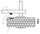
- Figs. 2 and 3 illustrate one magnet pair mounting arrangement used in conjunction with SUs 12, 14, 16, and 18 to provide sensor unit location signals according to the invention.
- Fig. 2 is a schematic side view showing the magnet pair mounting arrangement
- Fig. 3 is a schematic front view showing a tire and wheel mounted in operative relation to the magnet mounting arrangement of Fig. 2 .
- a pair of permanent magnets 31, 32 is secured to a suspension component 34 at a location adjacent a wheel mounting hub 35. Magnets 31, 32 are thus stationary with respect to the wheel and tire when the wheel and tire are rotating.
- the exact location of magnets 31, 32 is a function of the geometry of the wheel and tire and the location of the sensor unit. As seen in Fig.
- magnets 31, 32 are mounted on suspension unit 34 in a location at which the combined magnetic fields will encounter the magnetic field sensing element incorporated into sensor unit 12. Thus, whenever tire 11 is rotating, sensor unit 12 will encounter the combined magnetic field from magnets 31, 32 once per tire revolution.
- FIGs. 4 and 5 illustrate another magnet pair mounting arrangement used in conjunction with SUs 12, 14, 16, and 18 to provide sensor unit location signals according to the invention. This arrangement is used in those installations in which the sensor unit is mounted in the tread wall of the tire.
- Fig. 4 is a schematic perspective view showing this magnet pair mounting arrangement
- Fig. 5 is a schematic front view partially in section showing a tire and wheel mounted in operative relation to the magnet mounting arrangement of Fig. 4 .
- a pair of permanent magnets 31, 32 is secured to a mechanical component 37 (such as a fender) at a location adjacent the upper surface of the tire tread wall 38. Magnets 31, 32 are thus stationary with respect to the wheel and tire when the wheel and tire are rotating.
- magnets 31, 32 are mounted on mechanical component 37 at a location at which the combined magnetic fields will encounter the magnetic field sensing element incorporated into sensor unit 12. Thus, whenever tire 11 is rotating, sensor unit 12 will encounter the combined magnetic field from magnets 31, 32 once per tire revolution.
- Fig. 6 is a schematic block diagram of a preferred embodiment of a sensor unit SU.
- a magnetic field sensing element 41 illustrated as a multi-turn coil, is ohmically connected to two different circuit paths.
- the upper path comprises an analog-to-digital converter 42 having a pair of input terminals to which the output of magnetic field sensing element 41 is connected.
- the output of analog-to-digital converter 42 is connected to an input of a microcomputer unit 43.
- the lower path comprises a rectifier circuit 45 having a pair of input terminals to which the output of magnetic field sensing element 41 is connected.
- the output of rectifier circuit 45 is connected to a D.C. power regulator circuit 46.
- Elements 45, 46 function to develop D.C. power from the electrical current developed in coil 41 from passing through the magnetic field produced by magnets 31, 32 once per revolution of the associated tire. This process is more fully described in the afore-mentioned '278 application.
- One or more tire parameter sensors 47 supply tire parameter electrical signals representative of the value of the sensor measurement(s) to the microcomputer unit 43.
- Microcomputer unit 43 combines these signals with the digital version of the magnetic field sensing element 41 signals and supplies these to an r.f. generator 48.
- R.f. generator 48 converts the received signals and transmits the converted signals to central receiver processor 25, in which the received signals are processed and used to drive display/alarm unit 26. Since the received signals contain the magnetic field identification signals, the accompanying tire parameter measurement signals are correlated to the magnetic field identification signals.
- the microcomputer unit 43 and r.f. generator 48 are preferably combined in a commercially available Freescale type MC68HC908RF2 unit or the equivalent, having a transmitter section for generating r.f.
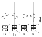
- Fig. 7 is a compound diagram illustrating four different, unique magnetic polarity orientations and the corresponding associated electric waveforms which uniquely identify the location of a given sensor unit 12, 14, 16, 18.
- magnets 31, 32 can be arranged in four different and unique magnetic polarity orientations: NS, SN, SS, and NN.
- N signifies that the north pole of the magnetic field generated by a magnet faces the viewer and the south pole is located at the hidden reverse surface of the magnet
- the legend S signifies that the south pole of the magnetic field generated by a magnet faces the viewer and the north pole is located at the hidden reverse surface of the magnet.
- the resulting induced analog electrical signal has a unique shape as illustrated for the four different magnetic orientations.
- Each unique shape is permanently assigned to a tire location on the vehicle.
- the uppermost signal shape is assigned to the front right tire location; the next signal shape is assigned to the front left tire location; the next signal shape is assigned to the rear right tire location; and the lowermost signal shape is assigned to the rear left tire location.
- the signal shape assignments are arbitrary: what is necessary is that the signal shape assignments be unique, invariant and programmed into the central receiver/processor 25. In this way, any tire parameter measurement signals received by the central receiver/processor 25 can be correlated to the transmitting location by the accompanying magnetic field sensing element signals.
- Fig. 8 illustrates a three magnet arrangement which can uniquely identify up to 8 individual tires. In general, for N magnets, the number of individual tires which can be uniquely identified is 2 exp N.
- the sensor unit has been described above as including an inductive D.C. power generating section comprising rectifier circuit 45 and D.C. power regulation unit 46, if desired this section may be omitted and some other D.C. power source-such as a battery-may be included. In such a configuration, the location signals and the sensor signals are processed in the same way as in the sensor unit described above.
- the invention provides a tire parameter sensing system incorporating a sensor unit location feature which is simple and inexpensive to implement, highly reliable, and accurate. Installation of systems according to the invention can be readily done at the vehicle factory as an integral part of the manufacturing operation, or by aftermarket installers to retro-fit existing vehicles with the latest tire parameter monitoring technology. Once installed, tires can be relocated to other arbitrary locations without affecting the accuracy and reliability of the location information.
Landscapes
- Engineering & Computer Science (AREA)
- Mechanical Engineering (AREA)
- Arrangements For Transmission Of Measured Signals (AREA)
- Measuring Fluid Pressure (AREA)
- Tires In General (AREA)
Applications Claiming Priority (1)
| Application Number | Priority Date | Filing Date | Title |
|---|---|---|---|
| US11/893,803 US7487671B1 (en) | 2007-08-18 | 2007-08-18 | Tire parameter monitoring system with sensor location using magnetic fields |
Publications (2)
| Publication Number | Publication Date |
|---|---|
| EP2028026A2 true EP2028026A2 (de) | 2009-02-25 |
| EP2028026A3 EP2028026A3 (de) | 2014-06-04 |
Family
ID=39944332
Family Applications (1)
| Application Number | Title | Priority Date | Filing Date |
|---|---|---|---|
| EP08252489.3A Withdrawn EP2028026A3 (de) | 2007-08-18 | 2008-07-22 | Reifenparameterüberwachungssystem mit Magnetfeldsensor |
Country Status (6)
| Country | Link |
|---|---|
| US (1) | US7487671B1 (de) |
| EP (1) | EP2028026A3 (de) |
| JP (1) | JP5552221B2 (de) |
| CN (1) | CN101380878B (de) |
| BR (1) | BRPI0802772B1 (de) |
| TW (1) | TWI430898B (de) |
Cited By (1)
| Publication number | Priority date | Publication date | Assignee | Title |
|---|---|---|---|---|
| WO2021116904A1 (de) * | 2019-12-08 | 2021-06-17 | Rainer Achterholt | Verfahren zum zuordnen von reifendruckmessungen eines kraftfahrzeugs zu radpositionen und vorrichtung zum bestimmen der radposition des gemessenen reifens |
Families Citing this family (13)
| Publication number | Priority date | Publication date | Assignee | Title |
|---|---|---|---|---|
| JP4544296B2 (ja) * | 2007-12-10 | 2010-09-15 | 株式会社日本自動車部品総合研究所 | 車輪位置検出装置におけるトリガ機搭載構造 |
| US7920058B2 (en) * | 2008-11-05 | 2011-04-05 | Ford Global Technologies | Trailer tire pressure monitoring system |
| US8594900B2 (en) | 2011-08-04 | 2013-11-26 | Motor Coach Industries Limited | Wheel end condition detection |
| KR101379652B1 (ko) | 2012-06-11 | 2014-04-02 | 현대모비스 주식회사 | 타이어 위치 정보 송신 장치 및 방법 |
| US9588019B2 (en) | 2012-11-06 | 2017-03-07 | Texas Research International, Inc. | Tire deformation sensor and tire inflation system |
| WO2014074491A1 (en) | 2012-11-06 | 2014-05-15 | Texas Research International, Inc. | Tire deformation sensor and tire inflation system |
| US10281298B2 (en) | 2016-07-22 | 2019-05-07 | Infineon Technologies Ag | Wheel localization from reference magnetic field and angular rotation information in TPMS application |
| TWI617117B (zh) * | 2016-10-19 | 2018-03-01 | 連益輝 | 車輛之輪胎磁力線圈裝置 |
| TWI617118B (zh) * | 2016-10-19 | 2018-03-01 | 連益輝 | 具有線圈電路片之輪胎 |
| TWI617119B (zh) * | 2016-10-19 | 2018-03-01 | 連益輝 | 用以附加於輪胎之線圈電路片 |
| DE102016225496A1 (de) * | 2016-12-19 | 2018-06-21 | Continental Automotive Gmbh | Elektronische Radeinheit und Steuereinrichtung für ein Radüberwachungssystem eines Fahrzeuges, Radüberwachungssystem für ein Fahrzeug sowie Verfahren zur Radüberwachung in einem Fahrzeug |
| CN110682744A (zh) * | 2019-10-15 | 2020-01-14 | 上海英恒电子有限公司 | 一种车辆、胎压监测系统、轮胎位置识别模块及方法 |
| CN116202459A (zh) * | 2023-03-04 | 2023-06-02 | 山东玲珑轮胎股份有限公司 | 一种可以记录并输出轮胎位移的装置 |
Citations (6)
| Publication number | Priority date | Publication date | Assignee | Title |
|---|---|---|---|---|
| US20030145650A1 (en) | 2002-02-04 | 2003-08-07 | Trw Inc. | Tire pressure monitoring system with pressure gauge operating mode for indicating when air pressure within a tire is within a predetermined pressure range |
| US6838985B2 (en) | 2002-03-25 | 2005-01-04 | Lear Corporation | System and method for remote tire pressure monitoring with low frequency initiation |
| US6959594B2 (en) | 2003-01-21 | 2005-11-01 | Silicon Valley Micro C Corp. | External mount tire pressure sensor system |
| US6998975B2 (en) | 2003-10-06 | 2006-02-14 | General Motors Corporation | Method and system for determining tire pressure imbalances |
| US7222523B1 (en) | 2005-11-04 | 2007-05-29 | Silicon Valley Micro C. Corp. | Tire pressure sensor system with improved sensitivity and power saving |
| US20070295070A1 (en) | 2006-06-22 | 2007-12-27 | Silicon Valley Micro C Corporation | Tire parameter monitoring system with inductive power source |
Family Cites Families (11)
| Publication number | Priority date | Publication date | Assignee | Title |
|---|---|---|---|---|
| US6591671B2 (en) * | 1999-08-16 | 2003-07-15 | The Goodyear Tire & Rubber Company | Monitoring pneumatic tire conditions |
| US6788193B2 (en) * | 2002-03-01 | 2004-09-07 | Lear Corporation | System and method for tire pressure monitoring providing automatic tire location recognition |
| US6691567B2 (en) * | 2002-03-01 | 2004-02-17 | Lear Corporation | System and method for tire pressure monitoring including automatic tire location recognition |
| US6725712B1 (en) * | 2002-03-01 | 2004-04-27 | Lear Corporation | System and method for tire pressure monitoring with automatic tire location recognition |
| JP2004161113A (ja) * | 2002-11-12 | 2004-06-10 | Pacific Ind Co Ltd | タイヤ状態監視装置 |
| US6904796B2 (en) * | 2003-04-21 | 2005-06-14 | G-5 Electronics, Llc | Remote tire monitoring systems tool |
| JP2004352019A (ja) * | 2003-05-28 | 2004-12-16 | Pacific Ind Co Ltd | タイヤ状態監視装置の送信機及びタイヤ状態監視装置 |
| JP2005231579A (ja) * | 2004-02-23 | 2005-09-02 | Denso Corp | タイヤ空気圧監視装置 |
| JP2006160105A (ja) * | 2004-12-08 | 2006-06-22 | Denso Corp | 車輪位置検出装置およびそれを備えたタイヤ空気圧検出装置 |
| FR2879331B1 (fr) * | 2004-12-10 | 2007-02-02 | Siemens Vdo Automotive Sas | Procede et dispositif de localisation de la position droite ou gauche d'une roue de vehicule |
| CN100462703C (zh) * | 2005-04-01 | 2009-02-18 | 上海飞恩微电子有限公司 | 用于汽车轮胎压力监测的快速无线传感器初始化系统 |
-
2007
- 2007-08-18 US US11/893,803 patent/US7487671B1/en not_active Expired - Fee Related
-
2008
- 2008-07-18 TW TW097127344A patent/TWI430898B/zh not_active IP Right Cessation
- 2008-07-22 EP EP08252489.3A patent/EP2028026A3/de not_active Withdrawn
- 2008-08-14 JP JP2008208882A patent/JP5552221B2/ja not_active Expired - Fee Related
- 2008-08-15 BR BRPI0802772-2A patent/BRPI0802772B1/pt not_active IP Right Cessation
- 2008-08-18 CN CN200810212405.6A patent/CN101380878B/zh not_active Expired - Fee Related
Patent Citations (6)
| Publication number | Priority date | Publication date | Assignee | Title |
|---|---|---|---|---|
| US20030145650A1 (en) | 2002-02-04 | 2003-08-07 | Trw Inc. | Tire pressure monitoring system with pressure gauge operating mode for indicating when air pressure within a tire is within a predetermined pressure range |
| US6838985B2 (en) | 2002-03-25 | 2005-01-04 | Lear Corporation | System and method for remote tire pressure monitoring with low frequency initiation |
| US6959594B2 (en) | 2003-01-21 | 2005-11-01 | Silicon Valley Micro C Corp. | External mount tire pressure sensor system |
| US6998975B2 (en) | 2003-10-06 | 2006-02-14 | General Motors Corporation | Method and system for determining tire pressure imbalances |
| US7222523B1 (en) | 2005-11-04 | 2007-05-29 | Silicon Valley Micro C. Corp. | Tire pressure sensor system with improved sensitivity and power saving |
| US20070295070A1 (en) | 2006-06-22 | 2007-12-27 | Silicon Valley Micro C Corporation | Tire parameter monitoring system with inductive power source |
Cited By (1)
| Publication number | Priority date | Publication date | Assignee | Title |
|---|---|---|---|---|
| WO2021116904A1 (de) * | 2019-12-08 | 2021-06-17 | Rainer Achterholt | Verfahren zum zuordnen von reifendruckmessungen eines kraftfahrzeugs zu radpositionen und vorrichtung zum bestimmen der radposition des gemessenen reifens |
Also Published As
| Publication number | Publication date |
|---|---|
| BRPI0802772B1 (pt) | 2018-07-24 |
| JP5552221B2 (ja) | 2014-07-16 |
| TW200925005A (en) | 2009-06-16 |
| BRPI0802772A2 (pt) | 2010-11-16 |
| JP2009046121A (ja) | 2009-03-05 |
| TWI430898B (zh) | 2014-03-21 |
| US20090044616A1 (en) | 2009-02-19 |
| US7487671B1 (en) | 2009-02-10 |
| CN101380878B (zh) | 2013-05-08 |
| CN101380878A (zh) | 2009-03-11 |
| EP2028026A3 (de) | 2014-06-04 |
Similar Documents
| Publication | Publication Date | Title |
|---|---|---|
| US7487671B1 (en) | Tire parameter monitoring system with sensor location using magnetic fields | |
| US8289144B2 (en) | Tire parameter monitoring system with sensor location using RFID tags | |
| US7392119B2 (en) | Method and device for locating the position, on the right or on the left, of a wheel of a vehicle | |
| EP1419908B1 (de) | Verfahren und Vorrichtung zur Zuordnung von den Reifen mit den Reifenpositionen eines Fahrzeuges | |
| KR100683601B1 (ko) | 타이어 공기압 감시 시스템 | |
| US6967571B2 (en) | Tire condition monitoring apparatus | |
| JP4606026B2 (ja) | タイヤ圧力監視システム | |
| US6384720B1 (en) | System and method for sensing an operating parameter of a vehicle tire | |
| EP2018980A1 (de) | Reifenlokalisierungssystem | |
| US20030164758A1 (en) | System and method for tire pressure monitoring providing automatic tire location recognition | |
| US10093139B2 (en) | Tire-pressure sensor unit, a tire-pressure notification device, and vehicle | |
| US20070040660A1 (en) | Robust method and system for the automatic detection of a detached remote tire pressure sensor of a tire pressure monitoring system | |
| JP2008538540A (ja) | 自動車遠隔タイヤモニタシステムにおける単一無線周波数検知器を用いた車輪センサ位置測定 | |
| US7562568B2 (en) | Tire parameter sensor unit with real time data storage | |
| US6725712B1 (en) | System and method for tire pressure monitoring with automatic tire location recognition | |
| CN105008150A (zh) | 用于关联具有轮胎压力监测系统的车辆上的多个轮胎位置的方法 | |
| JP2012096640A (ja) | センサユニット登録システム及びセンサユニット登録方法 | |
| US20110288720A1 (en) | Method and device for identifying the position of a wheel of a vehicle | |
| US9090206B2 (en) | On-board low-power vehicle condition indicator | |
| US7750623B2 (en) | Method and device for locating the right or left position of a wheel of a vehicle | |
| JP4232687B2 (ja) | タイヤローテーション支援装置 | |
| EP1863655A1 (de) | Selbstlokalisierung für reifendrucküberwachungssysteme | |
| US7009498B2 (en) | Mirror arrangement for motor vehicles | |
| KR200337127Y1 (ko) | 타이어 상태 감지 장치 | |
| JP2005231579A (ja) | タイヤ空気圧監視装置 |
Legal Events
| Date | Code | Title | Description |
|---|---|---|---|
| PUAI | Public reference made under article 153(3) epc to a published international application that has entered the european phase |
Free format text: ORIGINAL CODE: 0009012 |
|
| AK | Designated contracting states |
Kind code of ref document: A2 Designated state(s): AT BE BG CH CY CZ DE DK EE ES FI FR GB GR HR HU IE IS IT LI LT LU LV MC MT NL NO PL PT RO SE SI SK TR |
|
| AX | Request for extension of the european patent |
Extension state: AL BA MK RS |
|
| PUAL | Search report despatched |
Free format text: ORIGINAL CODE: 0009013 |
|
| AK | Designated contracting states |
Kind code of ref document: A3 Designated state(s): AT BE BG CH CY CZ DE DK EE ES FI FR GB GR HR HU IE IS IT LI LT LU LV MC MT NL NO PL PT RO SE SI SK TR |
|
| AX | Request for extension of the european patent |
Extension state: AL BA MK RS |
|
| RIC1 | Information provided on ipc code assigned before grant |
Ipc: B60C 23/04 20060101AFI20140429BHEP |
|
| AKY | No designation fees paid | ||
| AXX | Extension fees paid |
Extension state: MK Extension state: AL Extension state: RS Extension state: BA |
|
| REG | Reference to a national code |
Ref country code: DE Ref legal event code: R108 |
|
| REG | Reference to a national code |
Ref country code: DE Ref legal event code: R108 Effective date: 20150211 |
|
| STAA | Information on the status of an ep patent application or granted ep patent |
Free format text: STATUS: THE APPLICATION IS DEEMED TO BE WITHDRAWN |
|
| 18D | Application deemed to be withdrawn |
Effective date: 20141205 |