EP2028085B1 - Boîte auxiliaire de vitesse pour une caravane - Google Patents
Boîte auxiliaire de vitesse pour une caravane Download PDFInfo
- Publication number
- EP2028085B1 EP2028085B1 EP20080162844 EP08162844A EP2028085B1 EP 2028085 B1 EP2028085 B1 EP 2028085B1 EP 20080162844 EP20080162844 EP 20080162844 EP 08162844 A EP08162844 A EP 08162844A EP 2028085 B1 EP2028085 B1 EP 2028085B1
- Authority
- EP
- European Patent Office
- Prior art keywords
- attachment means
- drive
- drive unit
- carrier
- assembly according
- Prior art date
- Legal status (The legal status is an assumption and is not a legal conclusion. Google has not performed a legal analysis and makes no representation as to the accuracy of the status listed.)
- Active
Links
Images


Classifications
-
- B—PERFORMING OPERATIONS; TRANSPORTING
- B62—LAND VEHICLES FOR TRAVELLING OTHERWISE THAN ON RAILS
- B62D—MOTOR VEHICLES; TRAILERS
- B62D59/00—Trailers with driven ground wheels or the like
- B62D59/04—Trailers with driven ground wheels or the like driven from propulsion unit on trailer
Definitions
- the present invention relates to a an auxiliary drive assembly for a caravan or trailer having a drive unit.
- the drive unit comprises a drive motor, and a reduction gear connected thereto, wherein said drive unit is provided with attachment means for attachment to a displaceable carrier.
- a drive unit of this type is generally known in the prior art. It is becoming more and more common to fit an auxiliary drive, in particular to caravans and other trailers which are relatively heavy and have to be moved for some reason or other while not being coupled to the towing vehicle. Such an auxiliary drive is moved in any suitable way from the rest position to the wheel to be driven. Such a movement may comprise a translation, rotation or combination thereof. Subsequently, the wheel is brought into engagement with the auxiliary drive. This engagement can also be effected in many ways. In most cases, a drive roller is used which presses on the tyre of the wheel. However, systems using gear wheels and the like are also known, in which it is not the tyre of the wheel in question that is brought into engagement, but rather another part connected to the wheel, such as a toothed brake drum.
- the present invention relates to all the above-described constructions.
- opposite wheels are driven by separate motors.
- the prior art in this case uses left-hand and right-hand auxiliary drives which are embodied so as to mirror one another.
- This relates to both the drive unit comprising a drive motor and reduction gear and the associated mechanism which is moved to and from the wheel in order to bring the motor/reduction gear and wheel into engagement with one another.
- EP 1 714 859 A1 discloses an auxiliary drive having a drive unit which is specifically built for left hand or right hand use.
- MU 7 701 737-4U discloses two wheels on a common shaft having a chain drive. Each chain is driven by the same type of engine which is mounted centrally relative to the related wheel. This can be effected by having the drive chain at one wheel between such wheel and the centre axis of the vehicle whilst at the other wheel the chain is outside from such wheel.
- the drive unit which is to be used for an auxiliary drive is embodied such that it can be used on both the left-hand and the right-hand side of the relevant trailer.
- the costs for production, transportation and storage can be significantly reduced and assembly can also be simplified and errors prevented.
- the concept of the invention can be realised in many ways. It is possible to arrange the relevant attachment means on either the motor or on the reduction gear. If an embodiment comprising a drive roller is used, a bearing support or a protective housing for the drive roller will generally be present and it is possible to arrange the attachment means there.
- the attachment means can be produced in two ways. Firstly, an attachment means, such as for example a bolt, or bolt holes can be provided in different locations with respect to the corresponding attachment means on the carrier of the auxiliary drive which is moved to and fro with respect to the tyre.
- Another possibility is to use different attachment means on the drive unit wherein a first attachment means is used exclusively for installation on the left-hand side and a second attachment means being used exclusively for installation on the right-hand side.
- a first attachment means is used exclusively for installation on the left-hand side
- a second attachment means being used exclusively for installation on the right-hand side.
- the attachment means comprise attachment flanges or parts which are embodied to bear against the attachment flanges, the attachment flanges in the latter case being arranged on the carrier. It is also possible to use a flange/flange construction with the drive unit/carrier combination.
- the invention also relates to a drive unit for an auxiliary drive for a caravan or trailer comprising a drive motor, and a reduction gear connected thereto, wherein said drive unit is provided with attachment means for attachment to a displaceable carrier, wherein said attachment means are embodied such that said drive unit can be attached to said carrier in two mirrored positions, wherein said attachment means comprise attachment means arranged on opposite sides of said drive motor and/or the reduction gear connected thereto.
- the present invention also relates to an assembly comprising the above-described drive unit and a displaceable carrier wherein said carrier is provided with further attachment means for co-operation with the attachment means on said drive unit.
- further attachment means may be embodied in the same manner as the above-described attachment means.
- the invention also relates to an auxiliary drive wherein the above assembly is used and the carrier is displaceable with respect to a frame.
- a frame may form an integral part of the relevant vehicle or a profile (structure) attached thereto.
- the displacement of the carrier with respect to the frame may be carried out in a rotating manner, but is carried out in a linear manner in a preferred embodiment.
- the present invention also relates to an auxiliary drive assembly which is suitable for driving a vehicle.
- This comprises two auxiliary drives and these are provided with identical drive units, as described above.
- the carriers are not identical, but identical following mirroring.
- Fig. 1 shows a caravan 1, which has a frame 2, a right-hand wheel 3 and left-hand wheel 4.
- An auxiliary drive 6 is associated with the right-hand wheel 3 and an auxiliary drive 5 is associated with the left-hand wheel 4.
- Each auxiliary drive is provided with its own electric motor, and the electric motors can be controlled independently of one another in order to enable a rotating movement.
- Fig. 2 shows a more detailed highly diagrammatic view of auxiliary drive 5, which illustrates that the beam 7 which is connected to the frame 2 is coupled in turn to a frame 8.
- Frame 8 is provided with two sliding rods on which a carriage or carrier 9 can move to and fro.
- the drive unit 25 arranged on the carrier 9 can be moved away from and towards the wheel 4 in order to be brought into or out of engagement with the tyre.
- the engagement of the wheel can be effected in another manner as well.
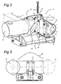
- the drive unit 25 comprises a motor 13 and a reduction gear 14 connected thereto and a drive roller 16 connected to the reduction gear 14.
- the free end of the drive roller is supported in a bearing housing 17 which is in turn connected to a roller housing 15 which, in turn, is attached to the transmission 14.
- This roller housing supports the motor/reduction gear and absorbs the drive forces.
- Such a roller housing may be the most important supporting part of the construction, as it absorbs the forces which act between the wall and the drive roller.
- the housing 15 is provided with a flange 11 provided with four threaded apertures 19 which are arranged symmetrically with respect to one another.
- Carrier 9 is provided with a corresponding flange 10 of so that bolts 21 which extend through flange 10 can be secured in the housing 15.
- the pattern of the threaded apertures 19 is symmetrical, so that it is possible to rotate the drive unit comprising motor 13, reduction gear 14 and drive roller 16 through 180 degrees with respect to the shaft 12, following which it is also possible to attach it to the flange 10.
- This is shown diagrammatically in Fig. 3 where arrow 20 is used to indicate that the motor 13 can be arranged on either the left-hand or right-hand side of the flange 11.
- a single drive unit comprising at least one drive motor and the associated reduction gear can be used both on the left-hand and on the right-hand side.
- a housing is present in the present example for the drive roller 16, the two parts also forming part of the drive unit.
- a construction is conceivable in which only the motor and reduction gear can be used as a single part on both sides.
- FIG. 4 Another example of the attachment means between the carrier and the drive unit is shown in Fig. 4 .
- reference numeral 28 denotes the sliding rods for the carrier or carriage 29.
- the drive unit is provided with a drive roller which is denoted by reference numeral 33.
- Reference numeral 36 denotes apertures and reference numeral 37 bolts. This makes it possible to produce attachment with respect to the carrier in two positions.
Landscapes
- Engineering & Computer Science (AREA)
- Chemical & Material Sciences (AREA)
- Combustion & Propulsion (AREA)
- Transportation (AREA)
- Mechanical Engineering (AREA)
- Rear-View Mirror Devices That Are Mounted On The Exterior Of The Vehicle (AREA)
- Arrangement Or Mounting Of Propulsion Units For Vehicles (AREA)
Claims (14)
- Mécanisme d'entraînement auxiliaire pour une caravane (1) ou une remorque comprenant deux entraînements auxiliaires (5, 6) pour les roues opposées (3, 4) d'un véhicule (1) comprenant deux unités d'entraînement identiques, chaque unité d'entraînement comprenant un moteur d'entrainement (13), et un réducteur qui y est relié (14), dans lequel ladite unité d'entraînement est munie de moyens de fixation pour la fixation à un support déplaçable (9), caractérisé en ce que lesdits moyens de fixation (11, 31, 32) sont incorporés de façon à ce que ladite unité d'entraînement puisse être attachée audit support dans deux positions miroirs, ainsi que deux supports (9) et structures (8) connectées aux dits supports, dans lequel lesdites unités d'entraînement identiques sont attachées à deux dits supports (9) en position miroir l'une par rapport à l'autre.
- Mécanisme selon la revendication 1, dans lequel lesdits moyens de fixation comprennent des moyens de fixation (31, 32) disposés sur les côtés opposés dudit moteur d'entrainement et/ou le réducteur qui y est relié.
- Mécanisme selon l'une quelconque des revendications précédentes, dans lequel lesdits moyens de fixation comprennent des moyens de fixation (11) qui sont arrangés symétriquement par rapport à ladite position miroir.
- Mécanisme selon l'une quelconque des revendications précédentes, dans lequel lesdits moyens de fixation comprennent une bride de fixation.
- Mécanisme comprenant une unité d'entraînement selon l'une quelconque des précédentes revendications et un rouleau d'entrainement (16) attaché au réducteur.
- Mécanisme selon la revendication 5, dans lequel ledit rouleau d'entrainement (16) est logé dans un logement de rouleau (15) comprenant lesdits moyens de fixation.
- Mécanisme comprenant une unité d'entraînement selon l'une des revendications 1-4 et un support déplaçable (9).
- Mécanisme selon la revendication 7, dans lequel ledit support déplaçable est muni avec des moyens de fixation supplémentaires (10, 30) qui coopèrent avec lesdits moyens de fixation, dans lequel lesdits moyens de fixation coopèrent dans deux positions miroirs avec lesdits moyens de fixation supplémentaires par contact engagé.
- Mécanisme selon la revendication 7 ou 8, dans lequel lesdits moyens de fixation et les moyens de fixation supplémentaires comprennent une bride de fixation et une bride de fixation supplémentaire, respectivement, dont les brides peuvent être connectées l'une à l'autre dans deux positions miroirs.
- Mécanisme selon l'une des revendications 7-9 comprenant une structure (8), dans laquelle ledit support (9) peut être déplacé par rapport à la structure.
- Mécanisme selon la revendication 10, dans lequel ledit support peut être déplacé linéairement par rapport à la structure.
- Mécanisme selon la revendication 1, dans lequel lesdits supports sont identiques dans un miroir.
- Mécanisme selon l'une des précédentes revendications 1 ou 12, dans lequel lesdits structures-supports sont identiques dans un miroir.
- Unité d'entraînement pour un entraînement auxiliaire pour une caravane (1) ou remorque selon la revendication 1 comprenant un moteur d'entrainement (13), et un réducteur qui y est relié (14), dans laquelle ladite unité d'entraînement est munie de moyens de fixation pour la fixation à un support déplaçable (9), caractérisée en ce que lesdits moyens de fixation (11, 31, 32) sont incorporés de façon à ce que ladite unité d'entraînement puisse être attachée au dit support dans deux positions miroirs, dans laquelle lesdits moyens de fixation comprennent des moyens de fixation (31, 32) disposés sur les côtés opposés dudit moteur d'entrainement et/ou le réducteur qui y est relié.
Applications Claiming Priority (1)
| Application Number | Priority Date | Filing Date | Title |
|---|---|---|---|
| NL2000829A NL2000829C2 (nl) | 2007-08-23 | 2007-08-23 | Hulpaandrijving voor een caravan. |
Publications (2)
| Publication Number | Publication Date |
|---|---|
| EP2028085A1 EP2028085A1 (fr) | 2009-02-25 |
| EP2028085B1 true EP2028085B1 (fr) | 2013-06-05 |
Family
ID=39135198
Family Applications (1)
| Application Number | Title | Priority Date | Filing Date |
|---|---|---|---|
| EP20080162844 Active EP2028085B1 (fr) | 2007-08-23 | 2008-08-22 | Boîte auxiliaire de vitesse pour une caravane |
Country Status (2)
| Country | Link |
|---|---|
| EP (1) | EP2028085B1 (fr) |
| NL (1) | NL2000829C2 (fr) |
Families Citing this family (1)
| Publication number | Priority date | Publication date | Assignee | Title |
|---|---|---|---|---|
| DE202014100738U1 (de) * | 2014-02-19 | 2014-03-20 | Truma Gerätetechnik GmbH & Co. KG | Rangierantrieb mit Spritzschutz für Anhänder oder dgl. |
Family Cites Families (2)
| Publication number | Priority date | Publication date | Assignee | Title |
|---|---|---|---|---|
| BR7701737U (pt) * | 1997-10-10 | 1999-06-01 | Jose Mauricio Xavier Carrenho | Mini rebocardor para avião |
| EP1714859B2 (fr) * | 2005-04-18 | 2012-04-18 | Truma Gerätetechnik GmbH & Co. KG | Entraînement auxiliaire compact pour remorque |
-
2007
- 2007-08-23 NL NL2000829A patent/NL2000829C2/nl not_active IP Right Cessation
-
2008
- 2008-08-22 EP EP20080162844 patent/EP2028085B1/fr active Active
Also Published As
| Publication number | Publication date |
|---|---|
| EP2028085A1 (fr) | 2009-02-25 |
| NL2000829C2 (nl) | 2009-02-24 |
Similar Documents
| Publication | Publication Date | Title |
|---|---|---|
| EP1840019B1 (fr) | Remorque avec motorisation auxiliaire | |
| US8376402B2 (en) | Lower type motor driven column apparatus | |
| US20110067946A1 (en) | Reducer of electric power steering apparatus | |
| US7854293B2 (en) | Steering operated by linear electric device | |
| US20120132020A1 (en) | Steering device | |
| EP2028085B1 (fr) | Boîte auxiliaire de vitesse pour une caravane | |
| EP1266817B1 (fr) | Direction assistée électrique | |
| WO2020067166A1 (fr) | Unité moyeu avec fonction de direction et véhicule doté de l'unité moyeu | |
| US6276476B1 (en) | Right hand drive steering system and conversion method from left hand drive vehicle | |
| GB2450863A (en) | Friction roller drive system for trailers | |
| EP2206641B1 (fr) | Entraînement auxiliaire pour une remorque | |
| US20160194077A1 (en) | Space-maximizing clutch arrangement for vehicle drive wheel | |
| EP2336011B1 (fr) | Unité de commande auxiliaire pour remorque | |
| US5152658A (en) | Hydrostatic system for lift truck | |
| FI89696B (fi) | Styrbar hjulaxel foer ett motorfordon | |
| KR102495327B1 (ko) | 피견인 트레일러 | |
| EP3634903B1 (fr) | Chariot élévateur à fourche monté sur camion pour charger et/ou décharger un espace de chargement, et procédé associé | |
| CN216690544U (zh) | 一种车辆转运架及立体车库 | |
| JP2000255308A (ja) | 重量物搬送車 | |
| EP1775196A3 (fr) | Pivot de roue orientable pour un véhicule industriel, en particulier chariots élévateurs, tracteurs, remorques ou similaire | |
| CN118850011B (zh) | 一种电动搬运车的可锁止车轮组 | |
| KR20220158354A (ko) | 전동 지게차용 전자식 주차 브레이크 | |
| JP5981160B2 (ja) | フォークリフト | |
| EP2028086A1 (fr) | Boîte auxiliaire | |
| KR200365104Y1 (ko) | 차량의 보조 바퀴용 조향 너클 고정장치 |
Legal Events
| Date | Code | Title | Description |
|---|---|---|---|
| PUAI | Public reference made under article 153(3) epc to a published international application that has entered the european phase |
Free format text: ORIGINAL CODE: 0009012 |
|
| AK | Designated contracting states |
Kind code of ref document: A1 Designated state(s): AT BE BG CH CY CZ DE DK EE ES FI FR GB GR HR HU IE IS IT LI LT LU LV MC MT NL NO PL PT RO SE SI SK TR |
|
| AX | Request for extension of the european patent |
Extension state: AL BA MK RS |
|
| AKX | Designation fees paid |
Designated state(s): DE FR GB NL |
|
| 17P | Request for examination filed |
Effective date: 20090825 |
|
| 17Q | First examination report despatched |
Effective date: 20110314 |
|
| GRAP | Despatch of communication of intention to grant a patent |
Free format text: ORIGINAL CODE: EPIDOSNIGR1 |
|
| RIN1 | Information on inventor provided before grant (corrected) |
Inventor name: BEIJERSBERGEN VAN HENEGOUWEN, CORNELIS MARTIN Inventor name: BENDER, STEFFEN |
|
| GRAS | Grant fee paid |
Free format text: ORIGINAL CODE: EPIDOSNIGR3 |
|
| GRAA | (expected) grant |
Free format text: ORIGINAL CODE: 0009210 |
|
| AK | Designated contracting states |
Kind code of ref document: B1 Designated state(s): DE FR GB NL |
|
| REG | Reference to a national code |
Ref country code: GB Ref legal event code: FG4D |
|
| REG | Reference to a national code |
Ref country code: DE Ref legal event code: R096 Ref document number: 602008025119 Country of ref document: DE Effective date: 20130801 |
|
| REG | Reference to a national code |
Ref country code: NL Ref legal event code: T3 |
|
| PLBE | No opposition filed within time limit |
Free format text: ORIGINAL CODE: 0009261 |
|
| STAA | Information on the status of an ep patent application or granted ep patent |
Free format text: STATUS: NO OPPOSITION FILED WITHIN TIME LIMIT |
|
| 26N | No opposition filed |
Effective date: 20140306 |
|
| REG | Reference to a national code |
Ref country code: FR Ref legal event code: ST Effective date: 20140430 |
|
| REG | Reference to a national code |
Ref country code: DE Ref legal event code: R097 Ref document number: 602008025119 Country of ref document: DE Effective date: 20140306 |
|
| PG25 | Lapsed in a contracting state [announced via postgrant information from national office to epo] |
Ref country code: FR Free format text: LAPSE BECAUSE OF NON-PAYMENT OF DUE FEES Effective date: 20130902 |
|
| REG | Reference to a national code |
Ref country code: DE Ref legal event code: R082 Ref document number: 602008025119 Country of ref document: DE Representative=s name: HOFSTETTER, SCHURACK & PARTNER PATENT- UND REC, DE |
|
| PGFP | Annual fee paid to national office [announced via postgrant information from national office to epo] |
Ref country code: GB Payment date: 20230824 Year of fee payment: 16 |
|
| PGFP | Annual fee paid to national office [announced via postgrant information from national office to epo] |
Ref country code: NL Payment date: 20240821 Year of fee payment: 17 |
|
| GBPC | Gb: european patent ceased through non-payment of renewal fee |
Effective date: 20240822 |
|
| PG25 | Lapsed in a contracting state [announced via postgrant information from national office to epo] |
Ref country code: GB Free format text: LAPSE BECAUSE OF NON-PAYMENT OF DUE FEES Effective date: 20240822 |
|
| PGFP | Annual fee paid to national office [announced via postgrant information from national office to epo] |
Ref country code: DE Payment date: 20250825 Year of fee payment: 18 |
|
| REG | Reference to a national code |
Ref country code: NL Ref legal event code: MM Effective date: 20250901 |