EP2028171A1 - Procédé et dispositif de fabrication de méthane liquide et/ou gazeux - Google Patents
Procédé et dispositif de fabrication de méthane liquide et/ou gazeux Download PDFInfo
- Publication number
- EP2028171A1 EP2028171A1 EP08104747A EP08104747A EP2028171A1 EP 2028171 A1 EP2028171 A1 EP 2028171A1 EP 08104747 A EP08104747 A EP 08104747A EP 08104747 A EP08104747 A EP 08104747A EP 2028171 A1 EP2028171 A1 EP 2028171A1
- Authority
- EP
- European Patent Office
- Prior art keywords
- methane
- heat exchanger
- line
- mixture
- gaseous
- Prior art date
- Legal status (The legal status is an assumption and is not a legal conclusion. Google has not performed a legal analysis and makes no representation as to the accuracy of the status listed.)
- Granted
Links
Images
Classifications
-
- C—CHEMISTRY; METALLURGY
- C07—ORGANIC CHEMISTRY
- C07C—ACYCLIC OR CARBOCYCLIC COMPOUNDS
- C07C7/00—Purification; Separation; Use of additives
-
- C—CHEMISTRY; METALLURGY
- C07—ORGANIC CHEMISTRY
- C07C—ACYCLIC OR CARBOCYCLIC COMPOUNDS
- C07C7/00—Purification; Separation; Use of additives
- C07C7/005—Processes comprising at least two steps in series
-
- C—CHEMISTRY; METALLURGY
- C10—PETROLEUM, GAS OR COKE INDUSTRIES; TECHNICAL GASES CONTAINING CARBON MONOXIDE; FUELS; LUBRICANTS; PEAT
- C10L—FUELS NOT OTHERWISE PROVIDED FOR; NATURAL GAS; SYNTHETIC NATURAL GAS OBTAINED BY PROCESSES NOT COVERED BY SUBCLASSES C10G OR C10K; LIQUIFIED PETROLEUM GAS; USE OF ADDITIVES TO FUELS OR FIRES; FIRE-LIGHTERS
- C10L3/00—Gaseous fuels; Natural gas; Synthetic natural gas obtained by processes not covered by subclass C10G, C10K; Liquefied petroleum gas
- C10L3/06—Natural gas; Synthetic natural gas obtained by processes not covered by C10G, C10K3/02 or C10K3/04
- C10L3/10—Working-up natural gas or synthetic natural gas
-
- F—MECHANICAL ENGINEERING; LIGHTING; HEATING; WEAPONS; BLASTING
- F25—REFRIGERATION OR COOLING; COMBINED HEATING AND REFRIGERATION SYSTEMS; HEAT PUMP SYSTEMS; MANUFACTURE OR STORAGE OF ICE; LIQUEFACTION SOLIDIFICATION OF GASES
- F25J—LIQUEFACTION, SOLIDIFICATION OR SEPARATION OF GASES OR GASEOUS OR LIQUEFIED GASEOUS MIXTURES BY PRESSURE AND COLD TREATMENT OR BY BRINGING THEM INTO THE SUPERCRITICAL STATE
- F25J3/00—Processes or apparatus for separating the constituents of gaseous or liquefied gaseous mixtures involving the use of liquefaction or solidification
- F25J3/06—Processes or apparatus for separating the constituents of gaseous or liquefied gaseous mixtures involving the use of liquefaction or solidification by partial condensation
- F25J3/0605—Processes or apparatus for separating the constituents of gaseous or liquefied gaseous mixtures involving the use of liquefaction or solidification by partial condensation characterised by the feed stream
- F25J3/061—Natural gas or substitute natural gas
-
- F—MECHANICAL ENGINEERING; LIGHTING; HEATING; WEAPONS; BLASTING
- F25—REFRIGERATION OR COOLING; COMBINED HEATING AND REFRIGERATION SYSTEMS; HEAT PUMP SYSTEMS; MANUFACTURE OR STORAGE OF ICE; LIQUEFACTION SOLIDIFICATION OF GASES
- F25J—LIQUEFACTION, SOLIDIFICATION OR SEPARATION OF GASES OR GASEOUS OR LIQUEFIED GASEOUS MIXTURES BY PRESSURE AND COLD TREATMENT OR BY BRINGING THEM INTO THE SUPERCRITICAL STATE
- F25J3/00—Processes or apparatus for separating the constituents of gaseous or liquefied gaseous mixtures involving the use of liquefaction or solidification
- F25J3/06—Processes or apparatus for separating the constituents of gaseous or liquefied gaseous mixtures involving the use of liquefaction or solidification by partial condensation
- F25J3/063—Processes or apparatus for separating the constituents of gaseous or liquefied gaseous mixtures involving the use of liquefaction or solidification by partial condensation characterised by the separated product stream
- F25J3/0635—Processes or apparatus for separating the constituents of gaseous or liquefied gaseous mixtures involving the use of liquefaction or solidification by partial condensation characterised by the separated product stream separation of CnHm with 1 carbon atom or more
-
- F—MECHANICAL ENGINEERING; LIGHTING; HEATING; WEAPONS; BLASTING
- F25—REFRIGERATION OR COOLING; COMBINED HEATING AND REFRIGERATION SYSTEMS; HEAT PUMP SYSTEMS; MANUFACTURE OR STORAGE OF ICE; LIQUEFACTION SOLIDIFICATION OF GASES
- F25J—LIQUEFACTION, SOLIDIFICATION OR SEPARATION OF GASES OR GASEOUS OR LIQUEFIED GASEOUS MIXTURES BY PRESSURE AND COLD TREATMENT OR BY BRINGING THEM INTO THE SUPERCRITICAL STATE
- F25J3/00—Processes or apparatus for separating the constituents of gaseous or liquefied gaseous mixtures involving the use of liquefaction or solidification
- F25J3/06—Processes or apparatus for separating the constituents of gaseous or liquefied gaseous mixtures involving the use of liquefaction or solidification by partial condensation
- F25J3/063—Processes or apparatus for separating the constituents of gaseous or liquefied gaseous mixtures involving the use of liquefaction or solidification by partial condensation characterised by the separated product stream
- F25J3/067—Processes or apparatus for separating the constituents of gaseous or liquefied gaseous mixtures involving the use of liquefaction or solidification by partial condensation characterised by the separated product stream separation of carbon dioxide
-
- F—MECHANICAL ENGINEERING; LIGHTING; HEATING; WEAPONS; BLASTING
- F25—REFRIGERATION OR COOLING; COMBINED HEATING AND REFRIGERATION SYSTEMS; HEAT PUMP SYSTEMS; MANUFACTURE OR STORAGE OF ICE; LIQUEFACTION SOLIDIFICATION OF GASES
- F25J—LIQUEFACTION, SOLIDIFICATION OR SEPARATION OF GASES OR GASEOUS OR LIQUEFIED GASEOUS MIXTURES BY PRESSURE AND COLD TREATMENT OR BY BRINGING THEM INTO THE SUPERCRITICAL STATE
- F25J2205/00—Processes or apparatus using other separation and/or other processing means
- F25J2205/20—Processes or apparatus using other separation and/or other processing means using solidification of components
-
- F—MECHANICAL ENGINEERING; LIGHTING; HEATING; WEAPONS; BLASTING
- F25—REFRIGERATION OR COOLING; COMBINED HEATING AND REFRIGERATION SYSTEMS; HEAT PUMP SYSTEMS; MANUFACTURE OR STORAGE OF ICE; LIQUEFACTION SOLIDIFICATION OF GASES
- F25J—LIQUEFACTION, SOLIDIFICATION OR SEPARATION OF GASES OR GASEOUS OR LIQUEFIED GASEOUS MIXTURES BY PRESSURE AND COLD TREATMENT OR BY BRINGING THEM INTO THE SUPERCRITICAL STATE
- F25J2205/00—Processes or apparatus using other separation and/or other processing means
- F25J2205/24—Processes or apparatus using other separation and/or other processing means using regenerators, cold accumulators or reversible heat exchangers
-
- F—MECHANICAL ENGINEERING; LIGHTING; HEATING; WEAPONS; BLASTING
- F25—REFRIGERATION OR COOLING; COMBINED HEATING AND REFRIGERATION SYSTEMS; HEAT PUMP SYSTEMS; MANUFACTURE OR STORAGE OF ICE; LIQUEFACTION SOLIDIFICATION OF GASES
- F25J—LIQUEFACTION, SOLIDIFICATION OR SEPARATION OF GASES OR GASEOUS OR LIQUEFIED GASEOUS MIXTURES BY PRESSURE AND COLD TREATMENT OR BY BRINGING THEM INTO THE SUPERCRITICAL STATE
- F25J2210/00—Processes characterised by the type or other details of the feed stream
- F25J2210/62—Liquefied natural gas [LNG]; Natural gas liquids [NGL]; Liquefied petroleum gas [LPG]
-
- F—MECHANICAL ENGINEERING; LIGHTING; HEATING; WEAPONS; BLASTING
- F25—REFRIGERATION OR COOLING; COMBINED HEATING AND REFRIGERATION SYSTEMS; HEAT PUMP SYSTEMS; MANUFACTURE OR STORAGE OF ICE; LIQUEFACTION SOLIDIFICATION OF GASES
- F25J—LIQUEFACTION, SOLIDIFICATION OR SEPARATION OF GASES OR GASEOUS OR LIQUEFIED GASEOUS MIXTURES BY PRESSURE AND COLD TREATMENT OR BY BRINGING THEM INTO THE SUPERCRITICAL STATE
- F25J2210/00—Processes characterised by the type or other details of the feed stream
- F25J2210/66—Landfill or fermentation off-gas, e.g. "Bio-gas"
-
- F—MECHANICAL ENGINEERING; LIGHTING; HEATING; WEAPONS; BLASTING
- F25—REFRIGERATION OR COOLING; COMBINED HEATING AND REFRIGERATION SYSTEMS; HEAT PUMP SYSTEMS; MANUFACTURE OR STORAGE OF ICE; LIQUEFACTION SOLIDIFICATION OF GASES
- F25J—LIQUEFACTION, SOLIDIFICATION OR SEPARATION OF GASES OR GASEOUS OR LIQUEFIED GASEOUS MIXTURES BY PRESSURE AND COLD TREATMENT OR BY BRINGING THEM INTO THE SUPERCRITICAL STATE
- F25J2220/00—Processes or apparatus involving steps for the removal of impurities
- F25J2220/60—Separating impurities from natural gas, e.g. mercury, cyclic hydrocarbons
- F25J2220/66—Separating acid gases, e.g. CO2, SO2, H2S or RSH
-
- F—MECHANICAL ENGINEERING; LIGHTING; HEATING; WEAPONS; BLASTING
- F25—REFRIGERATION OR COOLING; COMBINED HEATING AND REFRIGERATION SYSTEMS; HEAT PUMP SYSTEMS; MANUFACTURE OR STORAGE OF ICE; LIQUEFACTION SOLIDIFICATION OF GASES
- F25J—LIQUEFACTION, SOLIDIFICATION OR SEPARATION OF GASES OR GASEOUS OR LIQUEFIED GASEOUS MIXTURES BY PRESSURE AND COLD TREATMENT OR BY BRINGING THEM INTO THE SUPERCRITICAL STATE
- F25J2220/00—Processes or apparatus involving steps for the removal of impurities
- F25J2220/60—Separating impurities from natural gas, e.g. mercury, cyclic hydrocarbons
- F25J2220/68—Separating water or hydrates
-
- F—MECHANICAL ENGINEERING; LIGHTING; HEATING; WEAPONS; BLASTING
- F25—REFRIGERATION OR COOLING; COMBINED HEATING AND REFRIGERATION SYSTEMS; HEAT PUMP SYSTEMS; MANUFACTURE OR STORAGE OF ICE; LIQUEFACTION SOLIDIFICATION OF GASES
- F25J—LIQUEFACTION, SOLIDIFICATION OR SEPARATION OF GASES OR GASEOUS OR LIQUEFIED GASEOUS MIXTURES BY PRESSURE AND COLD TREATMENT OR BY BRINGING THEM INTO THE SUPERCRITICAL STATE
- F25J2220/00—Processes or apparatus involving steps for the removal of impurities
- F25J2220/80—Separating impurities from carbon dioxide, e.g. H2O or water-soluble contaminants
- F25J2220/82—Separating low boiling, i.e. more volatile components, e.g. He, H2, CO, Air gases, CH4
-
- F—MECHANICAL ENGINEERING; LIGHTING; HEATING; WEAPONS; BLASTING
- F25—REFRIGERATION OR COOLING; COMBINED HEATING AND REFRIGERATION SYSTEMS; HEAT PUMP SYSTEMS; MANUFACTURE OR STORAGE OF ICE; LIQUEFACTION SOLIDIFICATION OF GASES
- F25J—LIQUEFACTION, SOLIDIFICATION OR SEPARATION OF GASES OR GASEOUS OR LIQUEFIED GASEOUS MIXTURES BY PRESSURE AND COLD TREATMENT OR BY BRINGING THEM INTO THE SUPERCRITICAL STATE
- F25J2260/00—Coupling of processes or apparatus to other units; Integrated schemes
- F25J2260/20—Integration in an installation for liquefying or solidifying a fluid stream
-
- F—MECHANICAL ENGINEERING; LIGHTING; HEATING; WEAPONS; BLASTING
- F25—REFRIGERATION OR COOLING; COMBINED HEATING AND REFRIGERATION SYSTEMS; HEAT PUMP SYSTEMS; MANUFACTURE OR STORAGE OF ICE; LIQUEFACTION SOLIDIFICATION OF GASES
- F25J—LIQUEFACTION, SOLIDIFICATION OR SEPARATION OF GASES OR GASEOUS OR LIQUEFIED GASEOUS MIXTURES BY PRESSURE AND COLD TREATMENT OR BY BRINGING THEM INTO THE SUPERCRITICAL STATE
- F25J2270/00—Refrigeration techniques used
- F25J2270/02—Internal refrigeration with liquid vaporising loop
-
- F—MECHANICAL ENGINEERING; LIGHTING; HEATING; WEAPONS; BLASTING
- F25—REFRIGERATION OR COOLING; COMBINED HEATING AND REFRIGERATION SYSTEMS; HEAT PUMP SYSTEMS; MANUFACTURE OR STORAGE OF ICE; LIQUEFACTION SOLIDIFICATION OF GASES
- F25J—LIQUEFACTION, SOLIDIFICATION OR SEPARATION OF GASES OR GASEOUS OR LIQUEFIED GASEOUS MIXTURES BY PRESSURE AND COLD TREATMENT OR BY BRINGING THEM INTO THE SUPERCRITICAL STATE
- F25J2270/00—Refrigeration techniques used
- F25J2270/90—External refrigeration, e.g. conventional closed-loop mechanical refrigeration unit using Freon or NH3, unspecified external refrigeration
- F25J2270/904—External refrigeration, e.g. conventional closed-loop mechanical refrigeration unit using Freon or NH3, unspecified external refrigeration by liquid or gaseous cryogen in an open loop
-
- F—MECHANICAL ENGINEERING; LIGHTING; HEATING; WEAPONS; BLASTING
- F25—REFRIGERATION OR COOLING; COMBINED HEATING AND REFRIGERATION SYSTEMS; HEAT PUMP SYSTEMS; MANUFACTURE OR STORAGE OF ICE; LIQUEFACTION SOLIDIFICATION OF GASES
- F25J—LIQUEFACTION, SOLIDIFICATION OR SEPARATION OF GASES OR GASEOUS OR LIQUEFIED GASEOUS MIXTURES BY PRESSURE AND COLD TREATMENT OR BY BRINGING THEM INTO THE SUPERCRITICAL STATE
- F25J2280/00—Control of the process or apparatus
- F25J2280/30—Control of a discontinuous or intermittent ("batch") process
-
- Y—GENERAL TAGGING OF NEW TECHNOLOGICAL DEVELOPMENTS; GENERAL TAGGING OF CROSS-SECTIONAL TECHNOLOGIES SPANNING OVER SEVERAL SECTIONS OF THE IPC; TECHNICAL SUBJECTS COVERED BY FORMER USPC CROSS-REFERENCE ART COLLECTIONS [XRACs] AND DIGESTS
- Y02—TECHNOLOGIES OR APPLICATIONS FOR MITIGATION OR ADAPTATION AGAINST CLIMATE CHANGE
- Y02C—CAPTURE, STORAGE, SEQUESTRATION OR DISPOSAL OF GREENHOUSE GASES [GHG]
- Y02C20/00—Capture or disposal of greenhouse gases
- Y02C20/40—Capture or disposal of greenhouse gases of CO2
-
- Y—GENERAL TAGGING OF NEW TECHNOLOGICAL DEVELOPMENTS; GENERAL TAGGING OF CROSS-SECTIONAL TECHNOLOGIES SPANNING OVER SEVERAL SECTIONS OF THE IPC; TECHNICAL SUBJECTS COVERED BY FORMER USPC CROSS-REFERENCE ART COLLECTIONS [XRACs] AND DIGESTS
- Y02—TECHNOLOGIES OR APPLICATIONS FOR MITIGATION OR ADAPTATION AGAINST CLIMATE CHANGE
- Y02P—CLIMATE CHANGE MITIGATION TECHNOLOGIES IN THE PRODUCTION OR PROCESSING OF GOODS
- Y02P20/00—Technologies relating to chemical industry
- Y02P20/151—Reduction of greenhouse gas [GHG] emissions, e.g. CO2
Definitions
- the invention relates to an apparatus and a method for the separation of methane from methane-containing mixtures whose components have a boiling, melting or sublimation temperature which is higher than the boiling point of liquid methane, by the freezing of these components on the surface of a or multiple heat exchangers in which cryogenic liquefied natural gas ( LNG) is used as the coolant.
- LNG cryogenic liquefied natural gas
- dry ice can also be obtained with the apparatus and the method according to the present invention.
- the separated dry ice can furthermore be used as a cold source in a pretreatment unit for drying and cooling the methane-containing gas mixture.
- Gas mixtures which are to be used for energy generation usually require an increase in the energy density. For this purpose, it is necessary to remove incombustible inert gases from the gas mixture.
- cryogenic liquefied methane has a growing market potential as it represents the maximum energy density of this energy source and enables cost-effective transportation.
- LNG is used as an energy carrier for the operation of combined heat and power plants or as motor vehicle fuel. It can be obtained from natural gas as well as from biological-mechanical recycling of renewable raw materials and wastes and thus represents an energy source that can be produced independently of fossil resources.
- Examples include biogas or sewage gas, which in addition to methane contain a high carbon dioxide concentration. For this reason, special attention is paid to the separation of carbon dioxide from methane-containing mixtures.
- Known methods for separating the carbon dioxide from mixtures refer to the adsorption of carbon dioxide to a specific adsorbent, the gas scrubbing with water or chemicals, the permeation through special membranes or molecular sieves or the low-temperature distillation with liquefaction of carbon dioxide.
- These methods and devices for producing dry ice all use the cooling of a gas in the adiabatic expansion (Joule-Thomson effect) of gaseous or liquid carbon dioxide, which is under a pressure of about 55 bar and to about 4.8 bar or Atmospheric pressure is relaxed.
- the relaxation of the gas is usually done in a nozzle with special geometry to obtain a part of the desublimed carbon dioxide in the form of snow.
- the generated carbon dioxide snow is forced through slidable pistons into dry ice tablets or discs and ejected for further use.
- the previous method has in common that the optimized gas cleaning process takes place at elevated pressure, wherein the compression of the gas causes the largest proportion of the required power.
- the process control at high pressure more expensive fittings and pipes required, resulting in higher costs for investment and energy come about.
- dry ice is used in industrial and food-processing industries for cooling and is used as a residue-free blasting agent to remove coatings.
- the object of the present invention consists in the separation of methane from methane-containing mixtures with less energy.
- This object is achieved by the present invention by the separated gaseous methane from the outlet of a separation chamber, together with the evaporated methane from the heat exchangers, which are located in the separation chamber, at least partially guided into a liquefaction unit and liquefied there.
- the thus liquefied methane is used in the heat exchangers of the separation chamber as a coolant.
- the liquefied methane can be led into a tank and stored there.
- the gaseous, purified Methane be fed into a gas network.
- dry ice can be obtained from methane-containing mixtures containing a high concentration of carbon dioxide and used as the coolant of a heat exchanger of a pretreatment device.
- An advantage of the present invention is that much of the energy used for gas processing can be saved in gas liquefaction and / or gas purification.
- a methane-containing mixture is a gas mixture containing methane and incombustible inert gases.
- methane-containing mixtures are biogas, sewage gas, biogas and mine gas.
- Desublimation is the phase transition that leads from the gaseous state directly to the solid state of a substance.
- Freezing of a component of a gas mixture comprises all phase transitions, which lead to a solid state of the component, as well as the phase transition from gaseous to liquid, ie condensation, freezing and desublimation.
- An apparatus for separating methane from methane-containing mixtures whose components have a higher boiling, melting or sublimation temperature than the liquid methane, has at least one heat exchanger with a coolant inlet and a coolant outlet, a separation chamber which encloses the at least one heat exchanger and a Outlet for the separated, gaseous methane, a liquefaction unit, a line for the liquefied methane and a line for the gaseous methane on.
- the liquefied methane line connects the liquefaction unit to the at least one heat exchanger and the gaseous methane line connects the liquefaction unit to both the at least one heat exchanger and the separated gaseous methane outlet of the separation chamber.
- a device according to the invention can have more than just one heat exchanger. Then, the gaseous methane outlets of the plurality of heat exchangers are combined and connected to the liquefaction unit.
- the methane-containing mixture contains carbon dioxide in a high concentration
- it can be recovered on the surface of each heat exchanger by freezing. Due to the high Expansion coefficients of dry ice form as it cools cracks in the frozen on the surface of the heat exchanger layer. These cracks facilitate the detachment of the dry ice from the heat exchangers.
- the dry ice can be advantageously used as a coolant in a heat exchanger, which belongs to a pre-treatment device, continue to be used.
- each of the heat exchangers is designed as a plate heat exchanger. It is advantageous if the plates of each heat exchanger have a very smooth surface in order to facilitate the detachment of the frozen components of the methane-containing mixture from the heat exchangers.
- the heat exchanger surfaces are provided with a coating to which the dry ice adheres only to a small extent.
- the walls of the heat exchanger are made of stainless steel sheet (in particular of high-alloy, cold-resistant stainless steel) and bulge convexly outwards as soon as a pressure builds up inside.
- At least one of the heat exchangers has a heating element.
- Heating of the heat exchanger facilitates the detachment of the frozen components of the methane-containing mixture on the heat exchanger, on the one hand by the sublimation of the lowest layer of the frozen layer, on the other hand that the heat exchanger by means of valves in the line for the liquid methane and in the line for the gaseous methane can be separated from the remainder of the line system and the methane present in the heat exchanger is expanded by the heating and thus increases the pressure in the heat exchanger, resulting in a curvature of the surface of the heat exchanger to the outside.
- the device has a discharge system in which the detached frozen components of the methane-containing mixture are collected and collected.
- the discharge system preferably has a collecting trough, a piston which is actuated by means of a hydraulic system, a slide and a discharge line. It is of particular advantage that the device according to the invention via the discharge line of the discharge system to a pretreatment device by means of a heat exchanger for Recovery of the cold of the frozen components of the methane-containing mixture is connected.
- the heat exchanger for recovering the cold from the frozen components of the methane-containing mixture consists of a container, a line for the return of the coolant, a grate and grids which hold a bed of the frozen components of the methane-containing mixture and which Charging of coolant into the interstices of the bed allowed, from a line for the flow of cold coolant, from a line for the flow of the frozen during the cooling of the refrigerant frozen components of the methane-containing mixture and from a supply line for the frozen components of the methane-containing mixture, which branches off from the discharge line.
- the line for the return of the coolant is connected to the lower part of the container, while the line for the flow of the sublimated frozen components of the methane-containing mixture and the coolant are connected to the upper part of the container.
- an alcohol is used as the coolant, particularly preferably ethanol.
- methanol, propanol or butanol as a coolant is possible.
- the pretreatment device has a line which leads the methane-containing mixture through two heat exchangers to the separation chamber.
- the two heat exchangers are located in a common cooling circuit with the above-described heat exchanger for recovering the cold from the frozen components of the methane-containing mixture.
- two valves are provided, which can be switched in opposite directions, so that the coolant flows through only one of the two heat exchangers.
- the line through which the methane-containing mixture is passed through two heat exchangers to the separation chamber a line loop with two possible gas paths, which can be operated in different flow directions.
- the conduit loop has two inlets for the uncooled methane-containing mixture and an outlet for the pre-cooled methane-containing mixture.
- the pretreatment device has two valves, one of which is arranged on the supply line just before the inlets of the line loop and which can be switched to the opposite, so that the uncooled methane-containing mixture is passed only via an inlet in the line loop.
- the line loop of the pre-treatment device has two valves, wherein the first valve between the first inlet for the uncooled methane-containing mixture and the outlet for the pre-cooled methane-containing mixture is arranged and the second valve between the second inlet for the uncooled methane-containing mixture and the outlet for the pre-cooled methane-containing mixture is arranged. These two valves can be switched in opposite directions, whereby the flow direction can be reversed by the line loop.
- the device according to the invention has a tank for collecting the liquid methane, wherein the tank is connectable to the line for the liquefied methane which connects the liquefaction unit to the coolant inlet of the heat exchangers in the separation chamber.
- the tank with this line by means of a three-way controller is connectable.
- the liquid methane can be collected and provided for further uses.
- the device according to the invention has a connection to a gas network, for example a public gas network.
- this port is connected to or arranged in the line for the gaseous methane between the liquefaction unit and the separation chamber.
- This connection to a gas network makes it possible to feed separated and therefore purified gaseous methane into the gas network.
- this connection is designed as a three-way regulator, which is arranged in the line for the gaseous methane, wherein the separation chamber is connected in one position of the three-way controller with the liquefaction unit and in another position of the three-way Regulator connected to the gas network. Between three-way regulator and gas network can still be arranged a compressor to compress the gaseous methane to a pressure present in the gas network (usually between 6 bar and 90 bar).
- Preferred concentrations of residual substances in the gaseous methane flowing out of the outlet of the separation chamber are less than 5%, more preferably less than 3%.
- Methane-containing mixtures for which the device according to the present invention is particularly suitable contain carbon dioxide as the second main constituent, the concentration of carbon dioxide being not higher than 50% by volume, particularly preferred being a concentration of carbon dioxide of 40% by volume.
- biogases have a composition between [65% methane + 30% CO 2 ] and [50% methane + 45% CO 2 ].
- This invention further relates to a method for separating methane from methane-containing mixtures whose components have a higher boiling, melting or sublimation temperature than the liquid methane, wherein the methane-containing mixture is passed via an inlet into a separation chamber with at least one heat exchanger and the separated methane is passed through an outlet from the separation chamber.
- the separated methane from the outlet of the separation chamber together with vaporized methane from the at least one heat exchanger is at least partially passed into a liquefaction unit and liquefied in the liquefaction unit and the liquefied methane is passed from the liquefaction unit into the at least one heat exchanger.
- the methane-containing mixture flows over one or more heat exchangers, preferably plate heat exchangers.
- the plate heat exchangers are continuously filled with liquefied methane as a coolant at a temperature of about -162 ° C.
- At least part of the liquefied methane is passed into a tank connected to the liquefied methane line connecting the liquefaction unit to the coolant inlet of the heat exchangers in the separation chamber.
- the connection of the tank is made with this line by means of a three-way controller.
- liquid methane can be produced by the method according to the invention.
- only the portion of the separated methane is passed into the liquefaction unit, which is required to replace by the gas separation evaporated methane from the at least one heat exchanger by liquid methane as a coolant.
- the portion of the separated, gaseous methane, which is not needed as a replacement for the coolant, can be used for other purposes.
- gaseous methane can be produced by the method according to the invention.
- At least a portion of the separated methane from the outlet of the separation chamber is fed together with vaporized methane from the at least one heat exchanger in a gas network (for example, a public gas network) with the line for the gaseous methane, for example via a Three-way regulator is connected.
- a gas network for example, a public gas network
- the gaseous methane if necessary, with a compressor to a pressure present in the gas network (usually between 6 bar and 90 bar) are compressed.
- the methane-containing mixture By flowing over the heat exchanger, the methane-containing mixture is cooled to the condensation, sublimation or melting temperature of the other components of the methane-containing mixture. As a result, these components freeze on the surfaces of the heat exchanger and are then removed from the surface of the heat exchanger.
- the detachment of the frozen on the surfaces of the heat exchanger components of the methane-containing mixture from the surface of the heat exchanger takes place in that the layer consisting of these components due to their high volume expansion coefficient during cooling reduces their volume and thereby gets cracks and / or flakes off.
- the detachment of the frozen on the surfaces of the heat exchanger components of the methane-containing mixture from the surface of the heat exchanger by heating the heat exchanger, for example by means of a heat exchanger integrated in the heating element takes place.
- the bottom layer of the frozen-out components sublimes or melts and the top layers separate from the surface of the heat exchangers.
- the detachment of the frozen on the surfaces of the heat exchanger components of the methane-containing mixture from the surface of the heat exchanger is effected in that the surface of the heat exchanger is pressed by increasing the pressure in the interior of the heat exchanger to the outside.
- increasing the pressure in the interior of the heat exchanger takes place by pressure-tight sealing of the heat exchanger with respect to the Heat exchangers connected piping system and by heating the methane inside the heat exchanger.
- Preferred concentrations of residual substances in the gaseous methane flowing out of the outlet of the separation chamber are less than 5%, more preferably less than 3%.
- the frozen-out components are collected in a collecting trough.
- the frozen components collected in the catch tray are pushed out of the catch tray into a discharge line by a piston, which is preferably hydraulically, pneumatically or electrically driven.
- the discharge line may include a slide against which the frozen components are pressed to densify them. The slide can be opened periodically or at irregular intervals so that the frozen components can be pushed further into the discharge line.
- the methane-containing mixture used has a high concentration of carbon dioxide, which leads from the methane-containing mixture to the desublimation of carbon dioxide and thus suitable for the production of dry ice.
- Methane-containing mixtures for which the method according to the present invention is particularly suitable contain a concentration of carbon dioxide of not higher than 50% by volume, more preferably a concentration of carbon dioxide of 40% by volume.
- the methane-containing mixture is pre-cooled and dehumidified by the cooling capacity of the dry ice produced during the process.
- methane-containing gas mixtures in particular biogas have a high proportion of water.
- Water vapor that enters the separation chamber has a disruptive effect on the process, because the water vapor immediately freezes due to its high freezing point when the plate heat exchanger starts flowing, where it leads to heavy icing, which hinders the uniform flow through the separation chamber.
- the methane-containing mixture is pre-cooled and dehumidified by being passed over at least one heat exchanger whose cooling liquid is cooled by the cooling capacity of the dry ice produced.
- the methane-containing mixture is thereby pre-cooled and dehumidified, that it is passed through a line loop, which is in thermal contact with two heat exchangers, wherein the cooling liquid of a heat exchanger is cooled by the cooling capacity of the dry ice produced and the other heat exchanger is heated by the methane-containing mixture.
- the flow direction of the methane-containing mixture can be reversed by the line loop. The reversal of the flow direction is preferably in connection with the switching of the cooling circuit from one heat exchanger to the other to the first used for cooling heat exchanger, where the water is frozen out of the methane-containing mixture, defrost with the warm methane-containing mixture. The resulting water leaves the device via a discharge siphon.
- the methane-containing crude mixture i. the still untreated methane-containing mixture
- passed into the pretreatment device and through a first heat exchanger This first heat exchanger can be icy from the precycling on its outer walls and is not flowed through by the dry ice cooled coolant.
- the methane-containing crude mixture continues to flow over the second heat exchanger, which is flowed through by the cooled by the dry ice coolant.
- the water contained in the methane-containing raw mixture freezes on the outer walls of the second heat exchanger of the pretreatment device.
- the cooled methane-containing mixture leaves the pretreatment device and is preferably passed into the separation chamber.
- the cooling of the cooling liquid by the cooling capacity of the dry ice produced takes place in a further preferred embodiment of the method according to the invention in that the coolant is passed through a container which is charged with a bed of dry ice.
- the coolant optimally comes in contact with the dry ice.
- carbon dioxide is passed out of the container and can continue for cooling purposes - are also used in the context of the inventive method for further pre-cooling of the methane-containing mixture.
- the refrigerant flows through a return to a container which is charged with a bed of dry ice, wherein the bed is located on a grate and is held by grids.
- the coolant flows through the space in the dry ice bed and thereby releases heat to the dry ice and thus cools down.
- the cold coolant flows via a feed back into the circuit of the pretreatment device.
- an alcohol is used as a coolant to cool the heat exchangers for pre-cooling and dehumidifying the methane-containing mixture.
- ethanol is particularly preferred here.
- methanol, propanol or butanol is possible.
- the partial pressure difference of the methane-containing crude mixture at the inlet of the separation chamber to the separated methane at the outlet of the separation chamber is used as material flow pump. This eliminates the need for additional pumps which make the device more susceptible to maintenance and expensive, and consume additional energy. To compensate for pipeline losses, however, a pump or a blower can be used, which supports the transport of the methane-containing mixture through the device.
- the process according to the invention is carried out under atmospheric pressure. But it can also be carried out under overpressure, wherein the pressure in the separation chamber of the device should not be above the triple point of researcherfrierenden component to ensure the desublimation of this component.
- the pressure in the separation chamber should therefore not be above 5 bar.
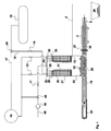
- a device according to the invention for carrying out the method according to the invention is shown.
- the device shown is suitable for the separation of methane from a methane-containing gas mixture which contains carbon dioxide as a further component.
- the illustrated device can also be used for the production of dry ice.
- the methane-containing mixture flows through the separation chamber (43), in which two heat exchangers (21) are arranged, before it through outlet openings (22), which are located between the heat exchangers (21) leaving the separation chamber (43).
- the methane-containing mixture cools down to below the sublimation temperature of the carbon dioxide, which thus desublimates on the surface of the heat exchanger (21).
- the reduction in volume due to the cooling of the methane-containing mixture and the phase transition of the carbon dioxide from the gas to the solid generates a negative pressure which sucks exactly the amount of methane-containing mixture that can be purified on the heat exchanger surfaces.
- the heat exchangers (21) are continuously filled with liquefied methane (30) which is used as a coolant for the heat exchangers at a temperature of about -162 ° C.
- the heat transferred in this process step leads to the evaporation of the liquefied methane in the interior of the heat exchangers, wherein the liquefied methane flows out as vaporized boil-off gas through the outlet openings (32).
- the three-way regulator (24) By controlling the three-way regulator (24) always flows as much liquefied methane into the interior of the heat exchanger, such as for gas separation, i. is needed to replace the boil-off gas.
- the gaseous fresh methane gas ie the methane purified in the separation chamber, flows out of the separation chamber through the discharge openings (22) attached to the upper end of the separation chamber and is sucked in by the liquefaction unit (16) and liquefied by cooling.
- the liquefaction unit sucks the vaporized methane gas (29) from the heat exchangers (21) and liquefies it.
- the produced liquefied methane flows via the line (15) in the heat exchanger (21), wherein the liquefied methane return via a three-way controller (24) is controlled as needed and the non-process required liquefied methane through the line (17) in the tank (18) is passed.
- a three-way controller In the line for the gaseous methane from the separation chamber (43) to the liquefaction unit (16) is a three-way controller (44). This connects in a first position the separation chamber (43) with the liquefaction unit (16), so that the separated, purified methane is sucked in by the liquefaction unit (16) as described above. In a second position of the three-way controller (44), the connection between the separation chamber (43) and liquefaction unit (16) is blocked and the gaseous methane from the separation chamber is instead sucked and compressed by a compressor (45). The compressed gaseous methane is then fed via line (46) into the public gas grid.
- a dry ice layer (31) builds up on the surface of the heat exchanger (21) and has to be cleaned periodically.
- the detachment of the dry ice is promoted by the particularly low roughness of the heat exchanger surface (25).
- An electric heater (28) which is arranged in the interior of the heat exchanger, supports the detachment of the dry ice by two mechanisms.
- the activation of the heating leads to the evaporation of the liquefied methane inside the heat exchanger to methane gas, which with closed valve (13) pushes the liquefied methane back into the supply line (15) until only gaseous methane is in the heat exchanger to be defrosted.
- the valve (14) of the liquefied methane feed line the thermal expansion of the gaseous methane leads to bulging of the heat exchanger surface (25) and thus to detachment of the dry ice layers (31).
- adhering dry ice in the lower part of the layer is evaporated by the heating heat, whereby the detachment is further supported.
- the valve (11) is shut off because the gas is not sufficiently separated.
- the detached dry ice lumps (33) fall into the discharge trough (20) of the discharge system located at least as far below the lower edge of the heat exchangers to ensure complete removal of the dry ice layers from the interstices of the heat exchangers.
- the dry ice lumps are periodically removed from the collection trough (20) by a piston (19) driven by a hydraulic system (23), the dry ice being first pressed against a closed slide (27). Once a compact dry ice plug (34) has formed, which seals the discharge line, the slide (27) is permanently opened and the Dry ice plug is pushed into the discharge line (5) containing the pretreatment device (in Fig. 2 shown) supplied with dry ice. The outflow of the methane-containing gas mixture to be separated is prevented by the compact dry ice plug, which seals the discharge line (5).
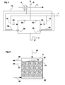
- a preferred device of the heat exchanger (4) for recovering the cold from the dry ice consists of a container which is fed with a bed of dry ice (39), wherein the dry ice branched off from the discharge line (5) and via the supply line (35) the container is introduced.
- the heat exchanger (4) is filled via a return (38) with a coolant, wherein the coolant by flowing into the space of the dry ice charge (39) absorbs the cold and is thereby cooled.
- the cold coolant flows via a flow (37) back into the cooling circuit (10).
- the sublimated during the cooling of the coolant carbon dioxide is removed via a flow (36) and also used for the pretreatment of the gas mixture.
- the bed (39) is located on a grate (42) and by grids (41), which are located above the flow (37), held in the heat exchanger (4).
- the pre-treatment device off Fig. 2 is a loop with two possible gas paths, which can be operated in different flow directions and by switching the gas path allows a periodic defrosting.
- the two operating conditions are shown in the process flow diagram of the pretreatment.
- the redundant valves are in opposite switching state, depending on the gas path used.
- operating state 1 the valves (2a), (8b) and (6b) are opened, while the valves (2b), (8a) and (6a) are closed.
- the methane-containing crude mixture flows via the line (1a) first into the heat exchanger (3a), then into the heat exchanger (3b) and leaves the pretreatment device via the line (9).
- the coolant flows through the cooling circuit (10) exclusively the heat exchanger (3b).
- the heat exchanger (3a) is iced from the previous operating state on its outer walls and thaws now by the flow of warm methane-containing raw gas mixture, which is thereby precooled.
- the circulating coolant therein in the heat exchanger (4) from the discharged carbon dioxide in line (5) is cooled and in the Heat exchanger (3b) used for cooling the methane-containing crude mixture, wherein the water remaining in the methane-containing crude mixture freezes at the heat exchanger walls. If the heat exchanger not flown through with coolant is completely defrosted, it is switched to the operating state 2, in which the valves (2a), (8b) and (6b) are closed and the valves (2b), (8a) and (6a) are opened. As a result, the flow direction of the methane-containing crude gas mixture is reversed, so that the heat exchanger (3b) is defrosted. The precipitating in this pretreatment process water flows through a provided with a siphon drain (7).
- the pretreatment process is depressurized, i. under atmospheric pressure, from, wherein a volume flow of the methane-containing raw mixture is generated by a blower only to the extent that the pressure caused by the pipe friction pressure loss is compensated.
- the device according to the invention and the method according to the invention allow an energetically efficient separation of methane from methane-containing mixtures and thus both an energetically efficient production of liquid methane and an energy-efficient production of gaseous methane.
- methane-containing gas mixtures consisting essentially of methane and carbon dioxide (such as biogas, sewage gas, digester gas and mine gas)
- inventive device and method are also for methane-containing gas mixtures suitable, which contain other gases in addition to or instead of carbon dioxide.
Landscapes
- Chemical & Material Sciences (AREA)
- Engineering & Computer Science (AREA)
- Organic Chemistry (AREA)
- Oil, Petroleum & Natural Gas (AREA)
- General Engineering & Computer Science (AREA)
- Physics & Mathematics (AREA)
- Mechanical Engineering (AREA)
- Thermal Sciences (AREA)
- Chemical Kinetics & Catalysis (AREA)
- General Chemical & Material Sciences (AREA)
- Analytical Chemistry (AREA)
- Water Supply & Treatment (AREA)
- Separation By Low-Temperature Treatments (AREA)
- Organic Low-Molecular-Weight Compounds And Preparation Thereof (AREA)
Applications Claiming Priority (1)
| Application Number | Priority Date | Filing Date | Title |
|---|---|---|---|
| DE102007032536A DE102007032536B4 (de) | 2007-07-12 | 2007-07-12 | Verfahren und Vorrichtung zur Herstellung von flüssigem und/oder gasförmigem Methan |
Publications (2)
| Publication Number | Publication Date |
|---|---|
| EP2028171A1 true EP2028171A1 (fr) | 2009-02-25 |
| EP2028171B1 EP2028171B1 (fr) | 2010-05-05 |
Family
ID=40121458
Family Applications (1)
| Application Number | Title | Priority Date | Filing Date |
|---|---|---|---|
| EP08104747A Not-in-force EP2028171B1 (fr) | 2007-07-12 | 2008-07-14 | Procédé et dispositif de fabrication de méthane liquide et/ou gazeux |
Country Status (3)
| Country | Link |
|---|---|
| EP (1) | EP2028171B1 (fr) |
| AT (1) | ATE466827T1 (fr) |
| DE (2) | DE102007032536B4 (fr) |
Cited By (2)
| Publication number | Priority date | Publication date | Assignee | Title |
|---|---|---|---|---|
| CN108626969A (zh) * | 2018-05-16 | 2018-10-09 | 福州联众气体有限公司 | 采用液氮高效回收瓦斯气和煤层气的净化液化流程和装置 |
| CN109163505A (zh) * | 2018-07-14 | 2019-01-08 | 宁波高新区诠宝绶新材料科技有限公司 | 一种使用含铕隔热材料的空气分离设备 |
Families Citing this family (6)
| Publication number | Priority date | Publication date | Assignee | Title |
|---|---|---|---|---|
| RU2424478C2 (ru) * | 2009-02-02 | 2011-07-20 | ОБЩЕСТВО С ОГРАНИЧЕННОЙ ОТВЕТСТВЕННОСТЬЮ "ГАРАНТ-Экологические Технологии Энергосбережения" | Устройство для разделения биогаза на метан и двуокись углерода |
| FR2944096B1 (fr) | 2009-04-07 | 2012-04-27 | Ass Pour La Rech Et Le Dev De Methodes Et Processus Indutriels Armines | Procede et systeme frigorifique pour la recuperation de la froideur du methane par des fluides frigorigenes. |
| US8528225B2 (en) * | 2009-12-11 | 2013-09-10 | Wyssmont Company Inc. | Apparatus and method for continuous lyophilization |
| DE102010040423A1 (de) * | 2010-09-08 | 2012-03-08 | Awite Bioenergie Gmbh | Gastrocknungsvorrichtung |
| CN113175687B (zh) * | 2021-05-28 | 2024-07-23 | 哈尔滨工业大学 | 一种烟气二氧化碳捕集提纯系统及方法 |
| CN113881470B (zh) * | 2021-09-30 | 2024-04-05 | 深圳市英策科技有限公司 | 一种从含有甲烷的混合物中获得液态甲烷的设备及方法 |
Citations (2)
| Publication number | Priority date | Publication date | Assignee | Title |
|---|---|---|---|---|
| DE1181186B (de) | 1958-10-15 | 1964-11-12 | Laszlo Vahl Dr Ing | Verfahren und Anlage zur Herstellung von Trockeneis |
| US5956971A (en) * | 1997-07-01 | 1999-09-28 | Exxon Production Research Company | Process for liquefying a natural gas stream containing at least one freezable component |
Family Cites Families (3)
| Publication number | Priority date | Publication date | Assignee | Title |
|---|---|---|---|---|
| US6658890B1 (en) * | 2002-11-13 | 2003-12-09 | Conocophillips Company | Enhanced methane flash system for natural gas liquefaction |
| TWI314637B (en) * | 2003-01-31 | 2009-09-11 | Shell Int Research | Process of liquefying a gaseous, methane-rich feed to obtain liquefied natural gas |
| CR7129A (es) * | 2003-10-29 | 2003-11-17 | Carlos Eduardo Rold N Villalobos | Metodo y aparato para almacenar gases a baja temperatura utilizando un sistema de recuperacion de refrigeracion |
-
2007
- 2007-07-12 DE DE102007032536A patent/DE102007032536B4/de not_active Expired - Fee Related
-
2008
- 2008-07-14 EP EP08104747A patent/EP2028171B1/fr not_active Not-in-force
- 2008-07-14 AT AT08104747T patent/ATE466827T1/de active
- 2008-07-14 DE DE502008000611T patent/DE502008000611D1/de active Active
Patent Citations (2)
| Publication number | Priority date | Publication date | Assignee | Title |
|---|---|---|---|---|
| DE1181186B (de) | 1958-10-15 | 1964-11-12 | Laszlo Vahl Dr Ing | Verfahren und Anlage zur Herstellung von Trockeneis |
| US5956971A (en) * | 1997-07-01 | 1999-09-28 | Exxon Production Research Company | Process for liquefying a natural gas stream containing at least one freezable component |
Cited By (2)
| Publication number | Priority date | Publication date | Assignee | Title |
|---|---|---|---|---|
| CN108626969A (zh) * | 2018-05-16 | 2018-10-09 | 福州联众气体有限公司 | 采用液氮高效回收瓦斯气和煤层气的净化液化流程和装置 |
| CN109163505A (zh) * | 2018-07-14 | 2019-01-08 | 宁波高新区诠宝绶新材料科技有限公司 | 一种使用含铕隔热材料的空气分离设备 |
Also Published As
| Publication number | Publication date |
|---|---|
| DE102007032536B4 (de) | 2013-04-18 |
| DE102007032536A1 (de) | 2009-01-15 |
| ATE466827T1 (de) | 2010-05-15 |
| DE502008000611D1 (de) | 2010-06-17 |
| EP2028171B1 (fr) | 2010-05-05 |
Similar Documents
| Publication | Publication Date | Title |
|---|---|---|
| EP2028171B1 (fr) | Procédé et dispositif de fabrication de méthane liquide et/ou gazeux | |
| DE1601950A1 (de) | Verfahren und Vorrichtung zum Verfluessigen von natuerlichem Gas | |
| DE3149847A1 (de) | "verfahren zur entfernung von kohlenwasserstoffen und anderen verunreinigungen aus einem gas" | |
| DE102017003238B4 (de) | Verfahren und Anlagensystem zur Energieumwandlung mittels Kohlendioxid | |
| DE1254656B (de) | Verfahren zur Herstellung von fluessigem Parawasserstoff | |
| CH694000A5 (de) | Verfahren zur Verfluessigung eines Erdgasstroms, enthaltend mindestens eine einfrierbare Komponente. | |
| EP2503271A2 (fr) | Procédé et dispositif destinés au traitement d'un flux de gaz contenant du dioxyde de carbone | |
| DE1044845B (de) | Verfahren zur Abtrennung einer Komponente, insbesondere von Kohlendioxyd, aus einem Gasgemisch | |
| EP2494645A1 (fr) | Système de cellules électrochimiques et procédé de séchage de gaz de combustion d'un système de cellules électrochimiques | |
| WO2001014044A2 (fr) | Procede et dispositif de production de dioxyde de carbone a partir de gaz brules | |
| DE102013008535A1 (de) | Anlage zur Verringerung eines Kohlendioxidgehalts eines kohlendioxidhaltigen und kohlenwasserstoffreichen Gasstroms und entsprechendes Verfahren | |
| EP1892457B1 (fr) | Procédé et dispositif destinés à l'enregistrement de gaz combustible, en particulier de gaz naturel | |
| EP4284535A1 (fr) | Procédé d'élimination de co2 provenant d'un gaz contenant du méthane | |
| EP4446680A2 (fr) | Procédé et dispositif de liquéfaction de gaz | |
| DE102012208223A1 (de) | Anlage und Verfahren zur Kohlenstoffdioxid- und Wasserabscheidung | |
| DE102007027819A1 (de) | Verfahren zum Abkühlen kryogener Gaszerlegungseinheiten | |
| DE202022107105U1 (de) | Anlage zur Abkühlung mindestens eines Kältemittels und/oder mindestens eines Kälteträgers in einem offenen Prozess | |
| EP3144615B1 (fr) | Procede et dispositif de fabrication de glace seche | |
| DE102010049444A1 (de) | Verfahren zum Abkühlen eines kryogenen Gaszerlegers | |
| DE2344133A1 (de) | Verfahren zur verfluessigung von luft und verfluessigung deren komponenten | |
| DE4436384C2 (de) | Verfahren und Vorrichtung zur Verflüssigung von Gasen und Gasgemischen | |
| DE102023120075A1 (de) | Einheit zum Reinigen angesaugter Luft und System mit einer Flüssigluft-Energiespeicher- und Kraftwerksvorrichtung mit einer entsprechenden Einheit | |
| EP4065254A1 (fr) | Procédé et dispositif de purification de flux de gaz par condensation | |
| EP3710134B1 (fr) | Procédé et dispositif de nettoyage ou de décomposition et de refroidissement d'un mélange gazeux | |
| AT226656B (de) | Verfahren zum Verflüssigen von Erdgas |
Legal Events
| Date | Code | Title | Description |
|---|---|---|---|
| PUAI | Public reference made under article 153(3) epc to a published international application that has entered the european phase |
Free format text: ORIGINAL CODE: 0009012 |
|
| AK | Designated contracting states |
Kind code of ref document: A1 Designated state(s): AT BE BG CH CY CZ DE DK EE ES FI FR GB GR HR HU IE IS IT LI LT LU LV MC MT NL NO PL PT RO SE SI SK TR |
|
| AX | Request for extension of the european patent |
Extension state: AL BA MK RS |
|
| 17P | Request for examination filed |
Effective date: 20090803 |
|
| GRAP | Despatch of communication of intention to grant a patent |
Free format text: ORIGINAL CODE: EPIDOSNIGR1 |
|
| AKX | Designation fees paid |
Designated state(s): AT BE BG CH CY CZ DE DK EE ES FI FR GB GR HR HU IE IS IT LI LT LU LV MC MT NL NO PL PT RO SE SI SK TR |
|
| RAP1 | Party data changed (applicant data changed or rights of an application transferred) |
Owner name: BIOGAS SUED ENTWICKLUNGSGESELLSCHAFT OHG |
|
| GRAS | Grant fee paid |
Free format text: ORIGINAL CODE: EPIDOSNIGR3 |
|
| GRAA | (expected) grant |
Free format text: ORIGINAL CODE: 0009210 |
|
| AK | Designated contracting states |
Kind code of ref document: B1 Designated state(s): AT BE BG CH CY CZ DE DK EE ES FI FR GB GR HR HU IE IS IT LI LT LU LV MC MT NL NO PL PT RO SE SI SK TR |
|
| REG | Reference to a national code |
Ref country code: GB Ref legal event code: FG4D Free format text: NOT ENGLISH |
|
| REG | Reference to a national code |
Ref country code: CH Ref legal event code: EP |
|
| REG | Reference to a national code |
Ref country code: IE Ref legal event code: FG4D Free format text: LANGUAGE OF EP DOCUMENT: GERMAN |
|
| REG | Reference to a national code |
Ref country code: CH Ref legal event code: NV Representative=s name: SCHMAUDER & PARTNER AG PATENT- UND MARKENANWAELTE |
|
| REF | Corresponds to: |
Ref document number: 502008000611 Country of ref document: DE Date of ref document: 20100617 Kind code of ref document: P |
|
| REG | Reference to a national code |
Ref country code: NL Ref legal event code: T3 |
|
| LTIE | Lt: invalidation of european patent or patent extension |
Effective date: 20100505 |
|
| PG25 | Lapsed in a contracting state [announced via postgrant information from national office to epo] |
Ref country code: NO Free format text: LAPSE BECAUSE OF FAILURE TO SUBMIT A TRANSLATION OF THE DESCRIPTION OR TO PAY THE FEE WITHIN THE PRESCRIBED TIME-LIMIT Effective date: 20100805 Ref country code: ES Free format text: LAPSE BECAUSE OF FAILURE TO SUBMIT A TRANSLATION OF THE DESCRIPTION OR TO PAY THE FEE WITHIN THE PRESCRIBED TIME-LIMIT Effective date: 20100816 Ref country code: LT Free format text: LAPSE BECAUSE OF FAILURE TO SUBMIT A TRANSLATION OF THE DESCRIPTION OR TO PAY THE FEE WITHIN THE PRESCRIBED TIME-LIMIT Effective date: 20100505 Ref country code: SE Free format text: LAPSE BECAUSE OF FAILURE TO SUBMIT A TRANSLATION OF THE DESCRIPTION OR TO PAY THE FEE WITHIN THE PRESCRIBED TIME-LIMIT Effective date: 20100505 |
|
| PG25 | Lapsed in a contracting state [announced via postgrant information from national office to epo] |
Ref country code: IS Free format text: LAPSE BECAUSE OF FAILURE TO SUBMIT A TRANSLATION OF THE DESCRIPTION OR TO PAY THE FEE WITHIN THE PRESCRIBED TIME-LIMIT Effective date: 20100905 Ref country code: FI Free format text: LAPSE BECAUSE OF FAILURE TO SUBMIT A TRANSLATION OF THE DESCRIPTION OR TO PAY THE FEE WITHIN THE PRESCRIBED TIME-LIMIT Effective date: 20100505 Ref country code: HR Free format text: LAPSE BECAUSE OF FAILURE TO SUBMIT A TRANSLATION OF THE DESCRIPTION OR TO PAY THE FEE WITHIN THE PRESCRIBED TIME-LIMIT Effective date: 20100505 Ref country code: LV Free format text: LAPSE BECAUSE OF FAILURE TO SUBMIT A TRANSLATION OF THE DESCRIPTION OR TO PAY THE FEE WITHIN THE PRESCRIBED TIME-LIMIT Effective date: 20100505 Ref country code: SI Free format text: LAPSE BECAUSE OF FAILURE TO SUBMIT A TRANSLATION OF THE DESCRIPTION OR TO PAY THE FEE WITHIN THE PRESCRIBED TIME-LIMIT Effective date: 20100505 |
|
| REG | Reference to a national code |
Ref country code: IE Ref legal event code: FD4D |
|
| PG25 | Lapsed in a contracting state [announced via postgrant information from national office to epo] |
Ref country code: CY Free format text: LAPSE BECAUSE OF FAILURE TO SUBMIT A TRANSLATION OF THE DESCRIPTION OR TO PAY THE FEE WITHIN THE PRESCRIBED TIME-LIMIT Effective date: 20100609 Ref country code: PL Free format text: LAPSE BECAUSE OF FAILURE TO SUBMIT A TRANSLATION OF THE DESCRIPTION OR TO PAY THE FEE WITHIN THE PRESCRIBED TIME-LIMIT Effective date: 20100505 |
|
| BERE | Be: lapsed |
Owner name: BIOGAS SUD ENTWICKLUNGSGESELLSCHAFT OHG Effective date: 20100731 |
|
| PG25 | Lapsed in a contracting state [announced via postgrant information from national office to epo] |
Ref country code: EE Free format text: LAPSE BECAUSE OF FAILURE TO SUBMIT A TRANSLATION OF THE DESCRIPTION OR TO PAY THE FEE WITHIN THE PRESCRIBED TIME-LIMIT Effective date: 20100505 Ref country code: IE Free format text: LAPSE BECAUSE OF FAILURE TO SUBMIT A TRANSLATION OF THE DESCRIPTION OR TO PAY THE FEE WITHIN THE PRESCRIBED TIME-LIMIT Effective date: 20100505 Ref country code: DK Free format text: LAPSE BECAUSE OF FAILURE TO SUBMIT A TRANSLATION OF THE DESCRIPTION OR TO PAY THE FEE WITHIN THE PRESCRIBED TIME-LIMIT Effective date: 20100505 |
|
| PG25 | Lapsed in a contracting state [announced via postgrant information from national office to epo] |
Ref country code: SK Free format text: LAPSE BECAUSE OF FAILURE TO SUBMIT A TRANSLATION OF THE DESCRIPTION OR TO PAY THE FEE WITHIN THE PRESCRIBED TIME-LIMIT Effective date: 20100505 Ref country code: MC Free format text: LAPSE BECAUSE OF NON-PAYMENT OF DUE FEES Effective date: 20100731 Ref country code: CZ Free format text: LAPSE BECAUSE OF FAILURE TO SUBMIT A TRANSLATION OF THE DESCRIPTION OR TO PAY THE FEE WITHIN THE PRESCRIBED TIME-LIMIT Effective date: 20100505 Ref country code: RO Free format text: LAPSE BECAUSE OF FAILURE TO SUBMIT A TRANSLATION OF THE DESCRIPTION OR TO PAY THE FEE WITHIN THE PRESCRIBED TIME-LIMIT Effective date: 20100505 |
|
| PLBE | No opposition filed within time limit |
Free format text: ORIGINAL CODE: 0009261 |
|
| STAA | Information on the status of an ep patent application or granted ep patent |
Free format text: STATUS: NO OPPOSITION FILED WITHIN TIME LIMIT |
|
| PG25 | Lapsed in a contracting state [announced via postgrant information from national office to epo] |
Ref country code: IT Free format text: LAPSE BECAUSE OF FAILURE TO SUBMIT A TRANSLATION OF THE DESCRIPTION OR TO PAY THE FEE WITHIN THE PRESCRIBED TIME-LIMIT Effective date: 20100505 |
|
| 26N | No opposition filed |
Effective date: 20110208 |
|
| REG | Reference to a national code |
Ref country code: DE Ref legal event code: R097 Ref document number: 502008000611 Country of ref document: DE Effective date: 20110207 |
|
| PG25 | Lapsed in a contracting state [announced via postgrant information from national office to epo] |
Ref country code: GR Free format text: LAPSE BECAUSE OF FAILURE TO SUBMIT A TRANSLATION OF THE DESCRIPTION OR TO PAY THE FEE WITHIN THE PRESCRIBED TIME-LIMIT Effective date: 20100806 |
|
| PG25 | Lapsed in a contracting state [announced via postgrant information from national office to epo] |
Ref country code: BE Free format text: LAPSE BECAUSE OF NON-PAYMENT OF DUE FEES Effective date: 20100731 |
|
| PG25 | Lapsed in a contracting state [announced via postgrant information from national office to epo] |
Ref country code: MT Free format text: LAPSE BECAUSE OF FAILURE TO SUBMIT A TRANSLATION OF THE DESCRIPTION OR TO PAY THE FEE WITHIN THE PRESCRIBED TIME-LIMIT Effective date: 20100505 |
|
| PG25 | Lapsed in a contracting state [announced via postgrant information from national office to epo] |
Ref country code: PT Free format text: LAPSE BECAUSE OF FAILURE TO SUBMIT A TRANSLATION OF THE DESCRIPTION OR TO PAY THE FEE WITHIN THE PRESCRIBED TIME-LIMIT Effective date: 20101005 Ref country code: LU Free format text: LAPSE BECAUSE OF NON-PAYMENT OF DUE FEES Effective date: 20100714 Ref country code: BG Free format text: LAPSE BECAUSE OF FAILURE TO SUBMIT A TRANSLATION OF THE DESCRIPTION OR TO PAY THE FEE WITHIN THE PRESCRIBED TIME-LIMIT Effective date: 20100505 Ref country code: HU Free format text: LAPSE BECAUSE OF FAILURE TO SUBMIT A TRANSLATION OF THE DESCRIPTION OR TO PAY THE FEE WITHIN THE PRESCRIBED TIME-LIMIT Effective date: 20101106 |
|
| PG25 | Lapsed in a contracting state [announced via postgrant information from national office to epo] |
Ref country code: TR Free format text: LAPSE BECAUSE OF FAILURE TO SUBMIT A TRANSLATION OF THE DESCRIPTION OR TO PAY THE FEE WITHIN THE PRESCRIBED TIME-LIMIT Effective date: 20100505 |
|
| PG25 | Lapsed in a contracting state [announced via postgrant information from national office to epo] |
Ref country code: BG Free format text: LAPSE BECAUSE OF FAILURE TO SUBMIT A TRANSLATION OF THE DESCRIPTION OR TO PAY THE FEE WITHIN THE PRESCRIBED TIME-LIMIT Effective date: 20100805 |
|
| REG | Reference to a national code |
Ref country code: AT Ref legal event code: MM01 Ref document number: 466827 Country of ref document: AT Kind code of ref document: T Effective date: 20130714 |
|
| PG25 | Lapsed in a contracting state [announced via postgrant information from national office to epo] |
Ref country code: AT Free format text: LAPSE BECAUSE OF NON-PAYMENT OF DUE FEES Effective date: 20130714 |
|
| REG | Reference to a national code |
Ref country code: FR Ref legal event code: PLFP Year of fee payment: 9 |
|
| REG | Reference to a national code |
Ref country code: FR Ref legal event code: PLFP Year of fee payment: 10 |
|
| REG | Reference to a national code |
Ref country code: FR Ref legal event code: PLFP Year of fee payment: 11 |
|
| PGFP | Annual fee paid to national office [announced via postgrant information from national office to epo] |
Ref country code: NL Payment date: 20180730 Year of fee payment: 11 Ref country code: FR Payment date: 20180730 Year of fee payment: 11 |
|
| PGFP | Annual fee paid to national office [announced via postgrant information from national office to epo] |
Ref country code: CH Payment date: 20180827 Year of fee payment: 11 Ref country code: GB Payment date: 20180828 Year of fee payment: 11 |
|
| REG | Reference to a national code |
Ref country code: CH Ref legal event code: PL |
|
| GBPC | Gb: european patent ceased through non-payment of renewal fee |
Effective date: 20190714 |
|
| PG25 | Lapsed in a contracting state [announced via postgrant information from national office to epo] |
Ref country code: NL Free format text: LAPSE BECAUSE OF NON-PAYMENT OF DUE FEES Effective date: 20190801 Ref country code: GB Free format text: LAPSE BECAUSE OF NON-PAYMENT OF DUE FEES Effective date: 20190714 |
|
| REG | Reference to a national code |
Ref country code: NL Ref legal event code: MM Effective date: 20190801 |
|
| PG25 | Lapsed in a contracting state [announced via postgrant information from national office to epo] |
Ref country code: CH Free format text: LAPSE BECAUSE OF NON-PAYMENT OF DUE FEES Effective date: 20190731 Ref country code: LI Free format text: LAPSE BECAUSE OF NON-PAYMENT OF DUE FEES Effective date: 20190731 |
|
| PG25 | Lapsed in a contracting state [announced via postgrant information from national office to epo] |
Ref country code: FR Free format text: LAPSE BECAUSE OF NON-PAYMENT OF DUE FEES Effective date: 20190731 |
|
| REG | Reference to a national code |
Ref country code: DE Ref legal event code: R082 Ref document number: 502008000611 Country of ref document: DE Representative=s name: DF-MP DOERRIES FRANK-MOLNIA & POHLMAN PATENTAN, DE Ref country code: DE Ref legal event code: R081 Ref document number: 502008000611 Country of ref document: DE Owner name: FINSTERWALDER UMWELTTECHNIK GMBH & CO. KG, DE Free format text: FORMER OWNER: BIOGAS SUED ENTWICKLUNGSGESELLSCHAFT OHG, 83233 BERNAU, DE |
|
| PGFP | Annual fee paid to national office [announced via postgrant information from national office to epo] |
Ref country code: DE Payment date: 20200924 Year of fee payment: 13 |
|
| REG | Reference to a national code |
Ref country code: DE Ref legal event code: R119 Ref document number: 502008000611 Country of ref document: DE |
|
| PG25 | Lapsed in a contracting state [announced via postgrant information from national office to epo] |
Ref country code: DE Free format text: LAPSE BECAUSE OF NON-PAYMENT OF DUE FEES Effective date: 20220201 |