EP2028311A2 - Machine à coudre et procédé destiné à coudre un début de couture à l'aide d'une telle machine à coudre - Google Patents
Machine à coudre et procédé destiné à coudre un début de couture à l'aide d'une telle machine à coudre Download PDFInfo
- Publication number
- EP2028311A2 EP2028311A2 EP08014040A EP08014040A EP2028311A2 EP 2028311 A2 EP2028311 A2 EP 2028311A2 EP 08014040 A EP08014040 A EP 08014040A EP 08014040 A EP08014040 A EP 08014040A EP 2028311 A2 EP2028311 A2 EP 2028311A2
- Authority
- EP
- European Patent Office
- Prior art keywords
- thread
- upper thread
- clamp
- sewing machine
- pulling
- Prior art date
- Legal status (The legal status is an assumption and is not a legal conclusion. Google has not performed a legal analysis and makes no representation as to the accuracy of the status listed.)
- Granted
Links
Images



Classifications
-
- D—TEXTILES; PAPER
- D05—SEWING; EMBROIDERING; TUFTING
- D05B—SEWING
- D05B47/00—Needle-thread tensioning devices; Applications of tensometers
- D05B47/04—Automatically-controlled tensioning devices
-
- D—TEXTILES; PAPER
- D05—SEWING; EMBROIDERING; TUFTING
- D05B—SEWING
- D05B1/00—General types of sewing apparatus or machines without mechanism for lateral movement of the needle or the work or both
- D05B1/02—General types of sewing apparatus or machines without mechanism for lateral movement of the needle or the work or both for making single-thread seams
-
- D—TEXTILES; PAPER
- D05—SEWING; EMBROIDERING; TUFTING
- D05B—SEWING
- D05B19/00—Program-controlled sewing machines
- D05B19/02—Sewing machines having electronic memory or microprocessor control unit
- D05B19/12—Sewing machines having electronic memory or microprocessor control unit characterised by control of operation of machine
-
- D—TEXTILES; PAPER
- D05—SEWING; EMBROIDERING; TUFTING
- D05B—SEWING
- D05B19/00—Program-controlled sewing machines
- D05B19/02—Sewing machines having electronic memory or microprocessor control unit
- D05B19/12—Sewing machines having electronic memory or microprocessor control unit characterised by control of operation of machine
- D05B19/14—Control of needle movement, e.g. varying amplitude or period of needle movement
-
- D—TEXTILES; PAPER
- D05—SEWING; EMBROIDERING; TUFTING
- D05B—SEWING
- D05B47/00—Needle-thread tensioning devices; Applications of tensometers
Definitions
- the invention relates to a sewing machine according to the preamble of claim 1. Furthermore, the invention relates to a method for sewing a seam beginning with such a sewing machine.
- a generic sewing machine is known from the DE 102 34 251 A , The measures described there for retracting a free thread end of a needle thread are complex.
- a thread pulling device between the thread lever and a second upper thread clamp leads to the possibility of withdrawing a thread excess arising from a downward movement of the thread lever from the thread lever area to the upper thread supply and using the thread lever to pull back the upper thread when sewing the seam beginning in the sewing material free end of the upper thread at the seam beginning only slightly protrudes from the fabric.
- the upper thread is thereby withdrawn by a length corresponding to the thread path difference, which is brought about by the thread pulling device.
- the result is a visually pleasing seam beginning, without the need to further shorten the protruding free end of the upper thread by cutting. This is especially true in applications advantageous in which the optical seam quality is of particular interest, for example, when sewing leather in interior components of a motor vehicle.
- the thread pulling device can be designed as a separate component from the second controllable upper thread clamp.
- the thread pulling device can be designed as a thread follower cooperating with the upper thread in the course between the thread lever and the upper thread main tensioning device.
- An arrangement of the thread pulling device according to claim 2 has been found to be particularly favorable.
- a thread path difference according to claim 3 leads to a visually pleasing seam. Depending on the application of the sewing machine, other thread path differences are possible.
- a thread pulling device according to claim 4 can be integrated with little structural effort in an upper thread guide.
- thread-pulling positions allow an adaptation of the upper thread withdrawal at the beginning of the seam to each existing boundary conditions.
- the optional predeterminable thread-pulling positions can in particular be changed automatically. This can be automatically specified depending on the requirements of the sewing machine one of several possible thread path differences. This can for example be controlled depending on the respective sewing program selected by an operator. This changeover then takes place with the aid of a controlled drive of the thread pulling device.
- a drive according to claim 6 can be realized reliable, with fast changeover and at low cost.
- a pneumatic drive or a stepper motor drive to change the thread pulling device are possible.
- An arrangement of the thread pulling device according to claim 7 allows integration of the thread pulling device and the second needle thread clamp in a structural unit which can be mounted together.
- a control according to claim 9 prevents unnecessary driving the thread pulling device during sewing, so following the initial stitch.
- the thread pulling device is activated at the first stitch, ie at the beginning of the seam.
- the entire process of this first trick is performed with a fixed arm shaft speed, which is reduced compared to another operating speed of the arm shaft.
- a time delay according to claim 10 has been found to ensure a reliable sequence for the upper thread withdrawal at the beginning of the seam.
- the time delay should not fall below a certain minimum value for the withdrawal to be reliable.
- An absolute time delay according to claim 11 has proven to be particularly suitable for ensuring a reliable operation of the thread pulling device.
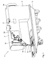
- a sewing machine 1 has an upper arm 2 and a lower case-like base plate 3, which are interconnected by a stand 4 to a C-shaped housing.
- the arm 2 is an arm shaft 5 (see. Fig.2 ), which is driven by a motor accommodated by means of a belt drive accommodated in the stand 4.
- a central control device 6 is connected, which in the Fig. 1 is shown schematically in the upper arm 2, but also at a different location and also relative to the sewing machine 1 can be arranged externally and connected thereto, for example via a cable harness.
- a needle bar 7 is driven up and down, at the lower end of a needle 8 is mounted. Through an eye of the needle 8, an upper thread 9 (see. Fig. 2 ).
- a gripper 10 is arranged, which in a conventional manner derived from the arm shaft 5 about a vertical axis of rotation 11 (see. Fig. 2 ) is rotary drivable.
- a bobbin or thread winding housing 12 of the gripper 10 is a supply of a lower thread 13 (see. Fig. 11 ).
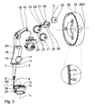
- Fig. 2 shows the leadership of the upper thread 9 of the sewing machine 1 in detail.
- a first upper thread clamp 14 is arranged, which has a clamping plate 15 which is displaceable relative to a base 16 of the first needle thread clamp 14.
- the first upper thread clamp 14 is in signal communication with the control device 6 and is displaceable between a thread clamping position in which the upper thread 9 is clamped at the location of the first upper thread clamp 14, and a thread release position in which the first upper thread clamp 14 releases the upper thread 9.
- the upper thread 9 runs substantially vertically.
- a passage location of the upper thread 9 through the first upper thread clamp 14 can be predetermined by means of a plurality of thread passage openings 17 in the base body 16.
- the upper thread 9 extends in the second thread passage opening 17 from the right of a total of four arranged transversely to the yarn transport direction yarn passage openings.
- a thread lever 18 is arranged, whose up and down movement is also derived from the arm shaft 5 in a conventional manner. Between a arranged at the free end of the thread lever 18 thread lever eye 19 and the first upper thread clamp 14 of the upper thread 9 still passes through a guide eye 20, the on in the Fig. 2 upper end of the base 16 is attached.
- the upper thread 9 passes through a needle thread main tensioning device 21.
- the latter has two operating in a conventional manner and in the upper thread transport direction directly behind each other arranged main voltage generator 22.
- the upper thread main tensioning device 21 is in signal communication with the central control device 6.
- the main voltage generator 22 set the upper thread 9 when activated by the control device 6 below a predetermined thread tension.
- a thread pulling device 24 is arranged upstream of the two main voltage generator 22, Upstream of the two main voltage generator 22, a thread pulling device 24 is arranged.
- the thread pulling device 24 has a pivotable arm 25, which is articulated via a pivot joint 26 on a clamping plate 27 of a second upper thread clamp 28.
- the thread pulling device 24 is thus mounted on the clamping plate 27 of the second upper thread clamp 28.
- the boom 25 of the thread pulling device 24 has a thread eye 29 which is deflectable transversely to the yarn path of the upper thread 9 between the upstream main voltage generator 22 and the second upper thread clamp 28.
- the boom 25 is changeable between a in the Fig. 2 shown neutral position and one in the Fig.
- This thread path difference is in the illustrated embodiment, for example, 20 millimeters.
- a thread guiding pin 31 is arranged in the upper thread course on a mounting plate 30 which is mounted on the arm 2.
- the two thread guide pins 31 cause regardless of whether the boom 25 in the thread pulling position or in the Neutral position is that the upper thread 9 at the same position from the second upper thread clamp 28 expires and enters the upstream main voltage generator 22.
- the boom 25 is convertible between the neutral position and the thread pulling position by an electromagnetic drive, which in turn is in signal communication with the control device 6.
- an electromagnetic drive the boom 25 can also be driven pneumatically or by a stepping motor.
- an upper thread biasing device 32 is arranged, which also operates in a conventional manner and can be in signal communication with the control device 6. Attached to the mounting plate 30 are, in addition to the guide pins 31, the upper thread main tensioning device 21 with the two main tension sensors 22, the second upper thread clamp 28 with the thread pulling device 24 mounted thereon, and the upper thread pretensioning device 32.
- the upper thread 9 passes through a thread passage opening 33, which in the mounting plate 30 in a in the Fig. 2 bent forwards and forwards by about 90 ° Edge area is executed.
- an upper thread bobbin Upstream of the thread passage opening 33, an upper thread bobbin, not shown, is arranged as an upper thread supply.
- FIGS. 2 to 10 show a momentary rotation positions of the arm shaft 5.
- a rotation angle scale 35 is arranged, which indicates a full revolution of the arm shaft 5 in 360 degrees angle steps. This degree of rotation angle scale 35 will be referred to in the following.
- FIGS. 2 and 3 show the arm shaft 5 in the position 205 °.
- the needle bar 7 is a bit far from its bottom dead center, which was reached at 180 °, returned again, so that next to the eye of the needle 8, a needle thread loop 36 has formed.
- a gripper tip 37 of the gripper 10 can engage in the upper thread loop 36 and then take the upper thread 9 with it.
- a sewing material plane NE is in the Fig. 3 represented by a line. This line corresponds to a support position of sewing material 38 on a throat plate 39 of the sewing machine. 1
- the first upper thread clamp 14 is in the thread clamping position.
- the upper thread main tensioning device 21 is deactivated so that it does not tension the upper thread 9.
- the thread pulling device 24 is in the neutral position.
- the second upper thread clamp 28 is in the thread clamping position.
- the upper thread pretensioner 32 is activated so as to keep the upper thread 9 between the upper thread spool and the upper thread pretensioner 32 under tension.
- the thread lever 18 is located on his way to bottom dead center. The thread lever 18 is already removed from its top dead center, so that between the two upper thread clamps 14, 28 results in a yarn excess, the thread there is therefore not tense, as in the Figures 2 and 3 shown. This excess yarn is in about twice the distance of the thread lever eye 19 from top dead center of the thread lever 18 to in the Figures 2 and 3 illustrated position 205 °.
- FIGS. 4 and 5 show the Armwellengnagnagna 225 °. Opposite the position after the Figures 2 and 3 Thus, the arm shaft 5 has rotated in the sewing operation direction by 20 °.
- the thread lever eye 19 is further lowered in the position 225 ° and before its bottom dead center.
- the thread pulling device 24 in the thread pulling position of the upper thread excess, which in the position according to the Figures 2 and 3 still present in the area of the thread lever eye 19, now withdrawn to the thread eye 29 of the thread pulling device 24.
- the upper thread 9 is now approximately stretched before.
- the gripper 10 has also rotated according to the rotation axis 11, namely by 40 ° about the axis of rotation 11. By the hook tip 37 of the upper thread 9 is now pulled down.
- FIGS. 6 and 7 show the Armwellengnagna 305 °. In position 305 °, the thread lever eye 19 is in the area of bottom dead center.
- the first upper thread clamp 14 is in the thread release position.
- the upper thread main tensioning device 21 is activated and keeps the upper thread 9 under tension.
- the boom 25 of the thread pulling device 24 is in the neutral position.
- the second upper thread clamp 28 is in the thread release position.
- the upper thread pretensioner 32 is activated. In position 305 °, the upper thread 9 has been pulled further down by the gripper 10.
- Fig. 8 shows the Armwellengnagnagnagnagna 0 °.
- the needle bar 7 is at top dead center. This position is selected at the beginning of the sewing, ie at the beginning of the seam, because there is the largest passage under the needle 8 for inserting the material 38.
- the first upper thread clamp 14 In the 0 ° position, the first upper thread clamp 14 is in the thread release position.
- the upper thread main tensioning device 21 is activated.
- the thread pulling device 24 is in the neutral position.
- the second needle thread clamp 28 is deactivated.
- the upper thread pretensioner 32 is activated.
- the thread lever 18 is on the way from bottom dead center to the top.
- Figures 9 and 10 show the Armwellengnagnagnagnagna 65 °.
- the needle 8 is on the way down.
- the two upper thread clamps 14 and 28 are in the release position.
- the upper thread main tensioning device 21 is activated.
- the upper thread pretensioner 32 is activated.
- the thread pulling device 24 is in the neutral position.
- the status information "seam beginning" in the control device 6 is converted into "running seam". A renewed change to "seam beginning” takes place after a thread trimming operation via the control device 6. This status information is queried during the further sewing process. The thread pulling device 24 is only activated if the status information "seam beginning" is present.
- the length of the over the fabric 3 8 protruding free end 40 can be determined by the angular position of the boom 25 in the thread pulling position.
- a plurality of initial thread lengths can be preselected.
- the angular position of the arm 25 triggered by the control device 6 results in the thread pulling position.
- a thread-pulling length which leads to a corresponding initial thread length, can alternatively also be set via a mechanical stop for the boom 25.
- the thread pulling device 24 is changed from the neutral position to the thread pulling position 50 ms after the simultaneous driving of the upper thread clamps 14 and 28 and the deactivation of the main upper thread tensioning device 21.
- the subsequent provisions ie the conversion of the upper thread clamps 14, 28 in the release position and the activation of the upper thread main tensioning device 21 and the return of the thread pulling device 24 in the neutral position, which are completed in the described embodiment already in the position 305 °, must in any case be completed to about 350 ° position to ensure trouble-free seam continuation.
- the time delay is predetermined by the control device 6, and is essentially dependent on the changeover time, which is required for a reliable switching of the upper thread clamps 14, 28 and the upper thread main tensioning device 21.
- This reduced arm shaft speed is also specified by the control device 6. Since the first stitch occurs at a fixed arm shaft speed, resulting for the time delay of the conversion of the thread pulling device 24 after driving the upper thread clamps 14 and 28 and the deactivation of the upper thread main tensioning device 21, a constant value of, for example, 50 ms.
- the time delay of the change of the thread pulling device 24 after the simultaneous activation of the thread clamps 14, 28 and the deactivation of the upper thread main tensioning device 21 can be predetermined independently of a variable possible speed of the arm shaft 5 of the sewing machine 1.
Landscapes
- Engineering & Computer Science (AREA)
- Textile Engineering (AREA)
- Computer Hardware Design (AREA)
- Microelectronics & Electronic Packaging (AREA)
- Sewing Machines And Sewing (AREA)
Applications Claiming Priority (1)
| Application Number | Priority Date | Filing Date | Title |
|---|---|---|---|
| DE102007039596A DE102007039596A1 (de) | 2007-08-22 | 2007-08-22 | Nähmaschine sowie Verfahren zum Nähen eines Nahtanfangs mit einer derartigen Nähmaschine |
Publications (3)
| Publication Number | Publication Date |
|---|---|
| EP2028311A2 true EP2028311A2 (fr) | 2009-02-25 |
| EP2028311A3 EP2028311A3 (fr) | 2011-10-19 |
| EP2028311B1 EP2028311B1 (fr) | 2013-10-09 |
Family
ID=40122460
Family Applications (1)
| Application Number | Title | Priority Date | Filing Date |
|---|---|---|---|
| EP08014040.3A Ceased EP2028311B1 (fr) | 2007-08-22 | 2008-08-06 | Machine à coudre et procédé destiné à coudre un début de couture à l'aide d'une telle machine à coudre |
Country Status (5)
| Country | Link |
|---|---|
| EP (1) | EP2028311B1 (fr) |
| JP (1) | JP5508698B2 (fr) |
| KR (1) | KR101410571B1 (fr) |
| CN (1) | CN101372797B (fr) |
| DE (1) | DE102007039596A1 (fr) |
Cited By (8)
| Publication number | Priority date | Publication date | Assignee | Title |
|---|---|---|---|---|
| ITVE20090067A1 (it) * | 2009-11-11 | 2011-05-12 | Chee Siang Ind Co Ltd | Dispositivo tirafilo agente all'avviamento del processo di cucitura per una macchina da cucire con la possibilità di taglio automatico del filo.- |
| DE102010043906A1 (de) | 2010-11-15 | 2012-05-16 | Dürkopp Adler AG | Nähmaschine sowie Verfahren zum Nähen eines Nahtanfangs mit einer derartigen Nähmaschine |
| EP2497852A1 (fr) | 2011-03-07 | 2012-09-12 | Dürkopp Adler AG | Machine à coudre et procédé destiné à coudre un début de couture à l'aide d'une telle machine à coudre |
| CN102041645B (zh) * | 2009-10-21 | 2012-10-17 | 启翔针车(上海)有限公司 | 自动切线缝纫机的起缝拉线装置 |
| EP2733246A1 (fr) * | 2012-11-19 | 2014-05-21 | Dürkopp Adler AG | Machine à coudre |
| DE102017206499B3 (de) | 2017-04-18 | 2018-05-03 | Dürkopp Adler AG | Nähmaschine |
| DE102017201240A1 (de) | 2017-01-26 | 2018-07-26 | Dürkopp Adler AG | Verfahren zur Erzeugung eines Naht-Anfangsoberfadens einer in Nähgut auszubildenden Naht mit einem definierten Soll-Nahtüberstand sowie Nähmaschine zur Durchführung eines derartigen Verfahrens |
| EP4257739A1 (fr) | 2022-04-07 | 2023-10-11 | Dürkopp Adler GmbH | Machine à coudre |
Families Citing this family (5)
| Publication number | Priority date | Publication date | Assignee | Title |
|---|---|---|---|---|
| JP5174414B2 (ja) | 2007-10-05 | 2013-04-03 | Juki株式会社 | ミシンの糸張力制御装置 |
| DE102009048794A1 (de) | 2009-10-08 | 2011-04-14 | CHEE SIANG INDUSTRIAL CO., LTD., Wugu | Fadenabziehvorrichtung beim Starten des Nähvorgangs für eine Nähmaschine mit der Möglichkeit zum automatischen Fadenschneiden |
| CN102220676B (zh) * | 2010-04-19 | 2012-11-14 | 启翔针车(上海)有限公司 | 缝纫机的针线供应器装置 |
| DE102012221060B3 (de) * | 2012-11-19 | 2014-02-06 | Dürkopp Adler AG | Nähmaschine |
| CN116516582B (zh) * | 2023-03-24 | 2026-04-14 | 浙江信胜科技股份有限公司 | 一种简易绳绣装置送绳张力控制方法 |
Citations (2)
| Publication number | Priority date | Publication date | Assignee | Title |
|---|---|---|---|---|
| DE10234251C1 (de) | 2002-07-27 | 2003-10-09 | Duerkopp Adler Ag | Verfahren zum Ziehen des freien Fadenendes eines Nadelfadens von der Oberseite eines Nähgutteils auf dessen Unterseite und Nähmaschine zur Durchführung des Verfahrens |
| DE102008016774A1 (de) | 2007-03-29 | 2008-10-02 | Juki Corp., Chofu | Nähmaschine |
Family Cites Families (9)
| Publication number | Priority date | Publication date | Assignee | Title |
|---|---|---|---|---|
| US3654883A (en) * | 1970-05-14 | 1972-04-11 | Union Special Machine Co | Thread control mechanism for sewing machines |
| DE2815297C2 (de) * | 1978-04-08 | 1983-01-13 | Dürkoppwerke GmbH, 4800 Bielefeld | Gesteuerte, im Bereich zwischen dem Fadenhebel u. dem Nadelöhr angeordnete, auf mindestens einen Nadelfaden einwirkende Fadenklemme einer Nähmaschine |
| DE3604299A1 (de) * | 1985-04-16 | 1986-10-16 | Kochs Adler Ag, 4800 Bielefeld | Verfahren zum ziehen des freien fadenendes eines nadelfadens von der oberseite eines naehguts auf dessen unterseite und vorrichtung zur durchfuehrung des verfahrens |
| DE4132991C1 (en) * | 1991-10-04 | 1992-12-03 | Duerkopp Adler Ag, 4800 Bielefeld, De | Producing seam having short thread ends on bottom of workpiece - involves drawing back needle thread from underside of workpiece so that only short thread piece remains on underside |
| JPH06134162A (ja) * | 1992-10-28 | 1994-05-17 | Juki Corp | ミシンの上糸供給制御装置 |
| JPH06190173A (ja) * | 1992-12-24 | 1994-07-12 | Juki Corp | ミシンの縫い始め針糸抜け防止装置 |
| US5931107A (en) * | 1997-12-22 | 1999-08-03 | Mcdonnell Douglas Corporation | Advanced stitching head for making stitches in a textile article having variable thickness |
| DE10344982A1 (de) * | 2003-09-27 | 2005-04-21 | Duerkopp Adler Ag | Fadenspann-Vorrichtung für eine Nähmaschine |
| DE102009048794A1 (de) * | 2009-10-08 | 2011-04-14 | CHEE SIANG INDUSTRIAL CO., LTD., Wugu | Fadenabziehvorrichtung beim Starten des Nähvorgangs für eine Nähmaschine mit der Möglichkeit zum automatischen Fadenschneiden |
-
2007
- 2007-08-22 DE DE102007039596A patent/DE102007039596A1/de not_active Withdrawn
-
2008
- 2008-08-06 EP EP08014040.3A patent/EP2028311B1/fr not_active Ceased
- 2008-08-20 KR KR1020080081354A patent/KR101410571B1/ko active Active
- 2008-08-21 JP JP2008212776A patent/JP5508698B2/ja active Active
- 2008-08-22 CN CN2008102133267A patent/CN101372797B/zh not_active Expired - Fee Related
Patent Citations (2)
| Publication number | Priority date | Publication date | Assignee | Title |
|---|---|---|---|---|
| DE10234251C1 (de) | 2002-07-27 | 2003-10-09 | Duerkopp Adler Ag | Verfahren zum Ziehen des freien Fadenendes eines Nadelfadens von der Oberseite eines Nähgutteils auf dessen Unterseite und Nähmaschine zur Durchführung des Verfahrens |
| DE102008016774A1 (de) | 2007-03-29 | 2008-10-02 | Juki Corp., Chofu | Nähmaschine |
Cited By (14)
| Publication number | Priority date | Publication date | Assignee | Title |
|---|---|---|---|---|
| CN102041645B (zh) * | 2009-10-21 | 2012-10-17 | 启翔针车(上海)有限公司 | 自动切线缝纫机的起缝拉线装置 |
| ITVE20090067A1 (it) * | 2009-11-11 | 2011-05-12 | Chee Siang Ind Co Ltd | Dispositivo tirafilo agente all'avviamento del processo di cucitura per una macchina da cucire con la possibilità di taglio automatico del filo.- |
| DE102010043906A1 (de) | 2010-11-15 | 2012-05-16 | Dürkopp Adler AG | Nähmaschine sowie Verfahren zum Nähen eines Nahtanfangs mit einer derartigen Nähmaschine |
| EP2453050A1 (fr) | 2010-11-15 | 2012-05-16 | Dürkopp Adler AG | Machine à coudre et procédé destiné à coudre un début de couture à l'aide d'une telle machine à coudre |
| EP2497852A1 (fr) | 2011-03-07 | 2012-09-12 | Dürkopp Adler AG | Machine à coudre et procédé destiné à coudre un début de couture à l'aide d'une telle machine à coudre |
| DE102011005198A1 (de) | 2011-03-07 | 2012-09-13 | Dürkopp Adler AG | Nähmaschine sowie Verfahren zum Nähen eines Nahtanfangs mit einer derartigen Nähmaschine |
| EP2733246A1 (fr) * | 2012-11-19 | 2014-05-21 | Dürkopp Adler AG | Machine à coudre |
| DE102017201240A1 (de) | 2017-01-26 | 2018-07-26 | Dürkopp Adler AG | Verfahren zur Erzeugung eines Naht-Anfangsoberfadens einer in Nähgut auszubildenden Naht mit einem definierten Soll-Nahtüberstand sowie Nähmaschine zur Durchführung eines derartigen Verfahrens |
| EP3354784A1 (fr) * | 2017-01-26 | 2018-08-01 | Dürkopp Adler AG | Procédé de préparation d'un fil supérieur d'extrémité d'une couture à réaliser dans un matériau à coudre, avec un excès de couture défini, ainsi que machine à coudre pour la mise en oeuvre de ce procédé |
| TWI787232B (zh) * | 2017-01-26 | 2022-12-21 | 德商都寇帕鷹股份有限公司 | 製造線縫開頭面線的方法和配置成實施這種方法的縫紉機 |
| DE102017206499B3 (de) | 2017-04-18 | 2018-05-03 | Dürkopp Adler AG | Nähmaschine |
| EP3392388A1 (fr) | 2017-04-18 | 2018-10-24 | Dürkopp Adler AG | Machine à coudre |
| EP4257739A1 (fr) | 2022-04-07 | 2023-10-11 | Dürkopp Adler GmbH | Machine à coudre |
| DE102022203472A1 (de) | 2022-04-07 | 2023-10-12 | Dürkopp Adler GmbH | Nähmaschine |
Also Published As
| Publication number | Publication date |
|---|---|
| CN101372797B (zh) | 2013-01-02 |
| JP5508698B2 (ja) | 2014-06-04 |
| CN101372797A (zh) | 2009-02-25 |
| KR101410571B1 (ko) | 2014-06-23 |
| KR20090020495A (ko) | 2009-02-26 |
| DE102007039596A1 (de) | 2009-02-26 |
| EP2028311A3 (fr) | 2011-10-19 |
| EP2028311B1 (fr) | 2013-10-09 |
| JP2009045468A (ja) | 2009-03-05 |
Similar Documents
| Publication | Publication Date | Title |
|---|---|---|
| EP2028311B1 (fr) | Machine à coudre et procédé destiné à coudre un début de couture à l'aide d'une telle machine à coudre | |
| DE19610818B4 (de) | Vorrichtung zum pneumatischen Verbinden von Faden oder Garn für den Einbau in Textilmaschinen, insbesondere in automatische Spulmaschinen | |
| EP0517045B1 (fr) | Machine de façonnage de fil, en particulier machine à broder comportant un dispositif de changement de fil | |
| EP2336413B1 (fr) | Machine à broder à blocs à aiguilles multiples, bloc à aiguilles multiples pour cette machine, ainsi qu'élément coupe fil et coupe-fil pour cette machine | |
| EP0902109B1 (fr) | Dispositif d'alimentation et de pinçage de fil de trame contrôlable et systeme comprenant ledit dispositif, pour la minimalisation des déchets de fil de trame durant le tissage sur métiers à tisser, plus particulièrement sur métiers à tisser à griffes | |
| DE2938894C2 (de) | Stickmaschine | |
| EP2497852B1 (fr) | Machine à coudre et procédé destiné à coudre un début de couture à l'aide d'une telle machine à coudre | |
| EP3176296A1 (fr) | Procédé de production d'un fil supérieur de démarrage de couture ayant un faible rentré théorique de couture et ensemble destiné à exécuter le procédé | |
| EP2453050B1 (fr) | Machine à coudre et procédé destiné à coudre un début de couture à l'aide d'une telle machine à coudre | |
| DE102009013155B4 (de) | Lochnähmaschine | |
| DE3604299A1 (de) | Verfahren zum ziehen des freien fadenendes eines nadelfadens von der oberseite eines naehguts auf dessen unterseite und vorrichtung zur durchfuehrung des verfahrens | |
| DE102013007928A1 (de) | Nähmaschine zur Erzeugung von Nähten mit kurzen Fadenanfangslängen | |
| DE102008011509B4 (de) | Fadenspannvorrichtung an einer Näh- oder Stickmaschine | |
| EP3354784B1 (fr) | Procédé de préparation d'un fil supérieur d'extrémité d'une couture à réaliser dans un matériau à coudre, avec un excès de couture défini, ainsi que machine à coudre pour la mise en oeuvre de ce procédé | |
| EP3360994A1 (fr) | Machine à coudre à point double ainsi que procédé d'obtention d'un fil supérieur de début de couture à faible surplomb | |
| DE10307022A1 (de) | Nähmaschine | |
| DE4118008C2 (fr) | ||
| DE102011054336A1 (de) | Verfahren und Vorrichtung zum Zunähen der Knöpfe auf einer Nähmaschine | |
| DE102004015813B3 (de) | Augen-Knopfloch-Nähmaschine | |
| EP3399088B1 (fr) | Module de production et machine à coudre pour produire un début de fil supérieur de couture dépassant d'une valeur de consigne | |
| EP0273350A2 (fr) | Procédé et dispositif pour guider les fils de trame dans les métiers à tisser | |
| WO1998007916A2 (fr) | Machine a broder a changeur de fil automatique | |
| EP0591570B1 (fr) | Machine de façonnage de fil, en particulier machine à broder comportant un dispositif de changement de fil | |
| DE2207366C3 (de) | Antrieb für Fadenzieher und Fadenwischer an einer Nähmaschine | |
| DE102013001346A1 (de) | Stickmaschine mit zumindest einem Doppelsteppstich-Umlaufgreifer |
Legal Events
| Date | Code | Title | Description |
|---|---|---|---|
| PUAI | Public reference made under article 153(3) epc to a published international application that has entered the european phase |
Free format text: ORIGINAL CODE: 0009012 |
|
| AK | Designated contracting states |
Kind code of ref document: A2 Designated state(s): AT BE BG CH CY CZ DE DK EE ES FI FR GB GR HR HU IE IS IT LI LT LU LV MC MT NL NO PL PT RO SE SI SK TR |
|
| AX | Request for extension of the european patent |
Extension state: AL BA MK RS |
|
| PUAL | Search report despatched |
Free format text: ORIGINAL CODE: 0009013 |
|
| AK | Designated contracting states |
Kind code of ref document: A3 Designated state(s): AT BE BG CH CY CZ DE DK EE ES FI FR GB GR HR HU IE IS IT LI LT LU LV MC MT NL NO PL PT RO SE SI SK TR |
|
| AX | Request for extension of the european patent |
Extension state: AL BA MK RS |
|
| RIC1 | Information provided on ipc code assigned before grant |
Ipc: D05B 47/00 20060101AFI20110915BHEP |
|
| 17P | Request for examination filed |
Effective date: 20120228 |
|
| AKX | Designation fees paid |
Designated state(s): CZ DE RO |
|
| REG | Reference to a national code |
Ref country code: DE Ref legal event code: R079 Ref document number: 502008010776 Country of ref document: DE Free format text: PREVIOUS MAIN CLASS: D05B0047020000 Ipc: D05B0047040000 |
|
| GRAP | Despatch of communication of intention to grant a patent |
Free format text: ORIGINAL CODE: EPIDOSNIGR1 |
|
| RIC1 | Information provided on ipc code assigned before grant |
Ipc: D05B 47/04 20060101AFI20121031BHEP |
|
| 17Q | First examination report despatched |
Effective date: 20130124 |
|
| GRAP | Despatch of communication of intention to grant a patent |
Free format text: ORIGINAL CODE: EPIDOSNIGR1 |
|
| INTG | Intention to grant announced |
Effective date: 20130523 |
|
| GRAS | Grant fee paid |
Free format text: ORIGINAL CODE: EPIDOSNIGR3 |
|
| GRAA | (expected) grant |
Free format text: ORIGINAL CODE: 0009210 |
|
| AK | Designated contracting states |
Kind code of ref document: B1 Designated state(s): CZ DE RO |
|
| REG | Reference to a national code |
Ref country code: RO Ref legal event code: EPE |
|
| REG | Reference to a national code |
Ref country code: DE Ref legal event code: R096 Ref document number: 502008010776 Country of ref document: DE Effective date: 20131205 |
|
| REG | Reference to a national code |
Ref country code: DE Ref legal event code: R097 Ref document number: 502008010776 Country of ref document: DE |
|
| PLBE | No opposition filed within time limit |
Free format text: ORIGINAL CODE: 0009261 |
|
| STAA | Information on the status of an ep patent application or granted ep patent |
Free format text: STATUS: NO OPPOSITION FILED WITHIN TIME LIMIT |
|
| 26N | No opposition filed |
Effective date: 20140710 |
|
| REG | Reference to a national code |
Ref country code: DE Ref legal event code: R097 Ref document number: 502008010776 Country of ref document: DE Effective date: 20140710 |
|
| PGFP | Annual fee paid to national office [announced via postgrant information from national office to epo] |
Ref country code: RO Payment date: 20190730 Year of fee payment: 12 Ref country code: CZ Payment date: 20190725 Year of fee payment: 12 |
|
| PGFP | Annual fee paid to national office [announced via postgrant information from national office to epo] |
Ref country code: DE Payment date: 20191025 Year of fee payment: 12 |
|
| REG | Reference to a national code |
Ref country code: DE Ref legal event code: R119 Ref document number: 502008010776 Country of ref document: DE |
|
| PG25 | Lapsed in a contracting state [announced via postgrant information from national office to epo] |
Ref country code: CZ Free format text: LAPSE BECAUSE OF NON-PAYMENT OF DUE FEES Effective date: 20200806 Ref country code: RO Free format text: LAPSE BECAUSE OF NON-PAYMENT OF DUE FEES Effective date: 20200806 |
|
| PG25 | Lapsed in a contracting state [announced via postgrant information from national office to epo] |
Ref country code: DE Free format text: LAPSE BECAUSE OF NON-PAYMENT OF DUE FEES Effective date: 20210302 |