EP2028345A2 - Turbine à vapeur - Google Patents
Turbine à vapeur Download PDFInfo
- Publication number
- EP2028345A2 EP2028345A2 EP08014840A EP08014840A EP2028345A2 EP 2028345 A2 EP2028345 A2 EP 2028345A2 EP 08014840 A EP08014840 A EP 08014840A EP 08014840 A EP08014840 A EP 08014840A EP 2028345 A2 EP2028345 A2 EP 2028345A2
- Authority
- EP
- European Patent Office
- Prior art keywords
- nozzle
- steam
- turbine
- nozzle box
- stage
- Prior art date
- Legal status (The legal status is an assumption and is not a legal conclusion. Google has not performed a legal analysis and makes no representation as to the accuracy of the status listed.)
- Withdrawn
Links
- 238000011144 upstream manufacturing Methods 0.000 claims abstract description 9
- 238000007789 sealing Methods 0.000 claims description 26
- 230000002093 peripheral effect Effects 0.000 description 14
- 238000012856 packing Methods 0.000 description 8
- 239000000463 material Substances 0.000 description 3
- 229910000990 Ni alloy Inorganic materials 0.000 description 1
- 238000010795 Steam Flooding Methods 0.000 description 1
- 230000015556 catabolic process Effects 0.000 description 1
- 238000006243 chemical reaction Methods 0.000 description 1
- 230000007423 decrease Effects 0.000 description 1
- 238000006731 degradation reaction Methods 0.000 description 1
- 230000000694 effects Effects 0.000 description 1
- 238000004519 manufacturing process Methods 0.000 description 1
Images




Classifications
-
- F—MECHANICAL ENGINEERING; LIGHTING; HEATING; WEAPONS; BLASTING
- F01—MACHINES OR ENGINES IN GENERAL; ENGINE PLANTS IN GENERAL; STEAM ENGINES
- F01D—NON-POSITIVE DISPLACEMENT MACHINES OR ENGINES, e.g. STEAM TURBINES
- F01D25/00—Component parts, details, or accessories, not provided for in, or of interest apart from, other groups
- F01D25/24—Casings; Casing parts, e.g. diaphragms, casing fastenings
- F01D25/26—Double casings; Measures against temperature strain in casings
-
- F—MECHANICAL ENGINEERING; LIGHTING; HEATING; WEAPONS; BLASTING
- F01—MACHINES OR ENGINES IN GENERAL; ENGINE PLANTS IN GENERAL; STEAM ENGINES
- F01D—NON-POSITIVE DISPLACEMENT MACHINES OR ENGINES, e.g. STEAM TURBINES
- F01D9/00—Stators
- F01D9/02—Nozzles; Nozzle boxes; Stator blades; Guide conduits, e.g. individual nozzles
- F01D9/04—Nozzles; Nozzle boxes; Stator blades; Guide conduits, e.g. individual nozzles forming ring or sector
- F01D9/047—Nozzle boxes
-
- F—MECHANICAL ENGINEERING; LIGHTING; HEATING; WEAPONS; BLASTING
- F05—INDEXING SCHEMES RELATING TO ENGINES OR PUMPS IN VARIOUS SUBCLASSES OF CLASSES F01-F04
- F05D—INDEXING SCHEME FOR ASPECTS RELATING TO NON-POSITIVE-DISPLACEMENT MACHINES OR ENGINES, GAS-TURBINES OR JET-PROPULSION PLANTS
- F05D2240/00—Components
- F05D2240/55—Seals
Definitions
- the present invention relates to a steam turbine and, more particularly, it relates to steam turbine designed to achieve a high efficiency by improving the nozzle box arrangement in the steam inlet section.
- a steam turbine comprises a rotatable turbine rotor, moving blade stages, a casing and nozzle diaphragms.
- the casing and the nozzle diaphragms constitute as a stationary section.
- the rotor is rotatably provided in the casing.
- the nozzle diaphragms are arranged substantially coaxially with the turbine rotor, supported on the casing.
- the moving blade stages are provided on the turbine rotor so as to rotate together with the turbine rotor.
- Each of the moving blade stages comprises a plurality of moving blades arranged in the circumferential direction of the turbine rotor.
- Each of the nozzle diaphragms comprises a plurality of turbine nozzles arranged in the circumferential direction relative to the turbine rotor and arranged at the upstream side of one of the moving blade stage.
- a pair of a nozzle diaphragm and a moving blade stage provided at the upstream side of the nozzle diaphragm forms a turbine stage.
- An ordinary steam turbine has a plurality of turbine stages.
- nozzle diaphragms, a turbine rotor and moving blade stages are substantially coaxially arranged in the casing.
- the steam led to a nozzle diaphragm passes through a plurality of turbine nozzles of the nozzle diaphragm and change its flowing direction.
- the steam flowing out from the nozzle diaphragm is led to a moving blade portion of a moving blade stage that forms a pair with the nozzle diaphragm.
- the steam drives the moving blade stage and the turbine rotor as it passes between the plurality of moving blades of the moving blade stage.
- an ordinary steam turbine has a plurality of turbine stages.
- the steam that passes through one turbine stage is led to an adjacent turbine stage.
- a plurality of moving blade stages are provided on the turbine rotor, separated from each other in the axial direction.
- the nozzle diaphragms are arranged in the casing so as to be placed between the moving blade stages in the axial direction of the turbine rotor.
- the moving blade portions of a plurality of moving blade stages and the turbine nozzle portions of a plurality of nozzle diaphragms form a steam passage.
- a nozzle box is provided in the casing to lead the steam introduced in the casing to the turbine nozzle of the first stage, which constitute as a part of the steam passage.
- Known nozzle boxes include one described in Japanese Patent Application Laid-Open Publication No. 03-066484 , the entire content of which is incorporated herein by reference.
- the nozzle box constitutes as the stationary section.
- the nozzle box comprises a plurality of turbine nozzles of the first stage, which are arranged in the circumferential direction, provided at the outlet side of the nozzle box.
- the nozzle box and the nozzle diaphragm of the first stage are arranged integrally and the steam introduced into the nozzle box is led to the steam passage, that includes the first moving blade stage that forms a pair with the first stage nozzle diaphragm provided with the nozzle box.
- FIGs. 5 and 6 are schematic axial cross-sectional views of a known steam turbine having a nozzle box.
- FIG. 5 is a schematic axial cross-sectional view along a vertical direction
- FIG. 6 is a schematic axial cross-sectional view along an angle inclined relative to the vertical direction by 45°.
- the steam turbine 1 has a casing 2, a turbine rotor 3 rotatably arranged in the casing 2, a nozzle diaphragms 4a1, 4a2, 4a3, ... that are rigidly secured to the casing 2.
- the casing 2 includes an outer casing 2a and an inner casing 2b.
- a plurality of moving blade stages 3a1, 3a2, 3a3, ... are arranged on the turbine rotor 3, which is a rotating section of the steam turbine 1, in the axial direction from the upstream side to the downstream side.
- Each of the moving blade stages 3a1, 3a2, 3a3 has a plurality of moving blades, the plurality of moving blades of the moving blade stages being denoted respectively by 3b1, 3b2, 3b3, ..., and rotating force is generated as steam flows, passing through between the rotors 3b1, 3b2, 3b3, ....
- Nozzle diaphragms 4a1, 4a2, 4a3, ... that are supported by the inner casing 2b are arranged between the moving blade stages 3a1, 3a2, 3a3, ... such that they are substantially coaxial and separated from each other in the axial direction.
- a plurality of turbine nozzles 4b1, 4b2, 4b3, ... are provided in the circumferential direction, respectively, with the nozzle diaphragms 4a1, 4a2, 4a3, ....
- the nozzle diaphragms 4a1, 4a2, 4a3, ... are supported by the casing 2 so as to constitute a stationary section of the steam turbine 1.
- the steam flow flowing through between the plurality of nozzle blades 4b1, 4b2, 4b3 arranged in the circumferential direction is changed its flowing direction so as to be led to the moving blades 3b1, 3b2, 3b3, ... of the moving blade stages 3a1, 3a2, 3a3, ... of the pairs.
- the flow path of the steam including the portions of the turbine nozzles 4b1, 4b2, 4b3, ... of the nozzle diaphragms 4a1, 4a2, 4a3, ... and the portions of the moving blades 3b1, 3b2, 3b3, ... of the moving blade stages 3a1, 3a2, 3a3 constitute as steam passage 8.
- the steam led to the steam turbine 1 flows through the steam passage 8 from an upstream side to a downstream side.
- the steam turbine 1 is provided with a steam inlet pipe 7 and a nozzle box 5 that constitutes as members for introducing steam into the steam passage 8.
- the nozzle box 5 is a pressure vessel that deals with high temperature and high pressure steam.
- An inlet section of the nozzle box 5 is connected to the steam inlet pipe 7.
- a steam outlet section, namely, outlet section, of the nozzle box 5 is integrally provided with the first stage nozzle diaphragm 4a1 and the plurality of turbine nozzles 4b1 that are arranged in the circumferential direction.
- the nozzle box 5 is rigidly secured to the casing 2 by a support member 6 arranged on the inner casing 2b.
- the nozzle box 5 is arranged substantially coaxial with the turbine rotor 3.
- the steam led into the nozzle box 5 from the steam inflow pipe 7 is then led to the first stage nozzle diaphragm 4a1 that operates as steam passage 8.
- the steam led to the steam passage 8 expands as it passes between the turbine nozzles 4b1, 4b2, 4b3, ... and the moving blades 3b1, 3b2, 3b3, ... and the thermal energy it has is converted into kinetic energy to drive the moving blade stages 3a1, 3a2, 3a3, ... and the turbine rotor 3 to rotate.
- the support member 6 is a member for supporting the nozzle box 5 in the inner casing.
- the support member 6 is not arranged entirely along the nozzle box 5 in the circumferential direction as seen in FIG. 6 .
- the pressure of the space around the nozzle box 5 (e.g. a space between the inner casing 2band the turbine rotor 3) is substantially equal to the pressure of the steam passage 8 near the outlet of the first moving blade stage 3a1.
- the steam conditions such as the temperature and the pressure of steam flowing into the steam turbine 1 are raised, the pressure of the steam flowing out from the first moving blade stage 3a1 is raised, and then the pressure in a space between the inner casing 2b and the turbine rotor 3 is also raised.
- the pressure applied to the internal casing 2b of the casing 2 is increased when applying the high pressure and high temperature steam to the steam turbine 1.
- Expensive material such as Ni alloy may have to be used as the material of the inner casing 2b in consideration of the thermal resistance of the steam turbine 1 when the temperature is raised among the steam conditions. These would result in higher manufacturing cost.
- An object of the present invention is to provide a steam turbine that can reduce force applied to the casing 2.
- a steam turbine comprising: a stationary section that includes a casing; a turbine rotor that includes a plurality of moving blade stages arranged in an axial direction, each of the moving blade stages being provided with a plurality of moving blades arranged in a circumferential direction, and rotatably provided in the casing; a plurality of nozzle diaphragms, wherein each of the nozzle diaphragms having a plurality of turbine nozzles arranged in the circumferential direction, provided substantially coaxially with the turbine rotor by being secured to the stationary section; and a nozzle box supported on the stationary section, wherein the nozzle box is arranged at an upstream side of the moving blade stages substantially coaxially with the turbine rotor so as to lead steam flowing toward the turbine rotor blades, characterized in that the nozzle box holds at least two stages of the nozzle diaphragms.
- FIG. 1 is a schematic axial cross-sectional view of the first embodiment of steam turbine according to the present invention taken along a plane inclined by 45° from the vertical direction.
- the components same as those of the known steam turbine shown in FIGs. 5 and 6 are denoted respectively by the same reference symbols and will not be described any further unless necessary.
- the steam turbine 1 of this embodiment has a casing 2, a turbine rotor 3 rotatably arranged in the casing 2 and nozzle diaphragms 4a1, 4a2, 4a3, ... rigidly secured to the casing 2.
- the casing 2 includes an outer casing 2a and an inner casing 2b.
- a plurality of moving blade stages 3a1, 3a2, 3a3, ... are arranged on the turbine rotor 3, which is a rotating section of the steam turbine 1 , in the axial direction from the upstream side to the downstream side.
- Each of the moving blade stages 3a1, 3a2, 3a3 has a plurality of moving blades, the plurality of moving blades of the moving blade stages being denoted respectively by 3b1, 3b2, 3b3, ..., and rotating force is generated as steam flows, passing between the rotors 3b1, 3b2, 3b3, ....
- Nozzle diaphragms 4a1, 4a2, 4a3, ... that are supported by the inner casing 2b are arranged between the moving blade stages 3a1, 3a2, 3a3, ... such that they are substantially coaxial with the turbine rotor 3 and separated from each other in the axial direction.
- a plurality of turbine nozzles 4b1, 4b2, 4b3, ... are provided in the circumferential direction, respectively with the nozzle diaphragms 4a1, 4a2, 4a3, .
- the nozzle diaphragms 4a1, 4a2, 4a3, ... are supported by the casing 2 so as to constitute a stationary section of the steam turbine 1.
- the steam flow flowing through between the plurality of turbine nozzles 4b1, 4b2, 4b3, ..., arranged in the circumferential direction, is changed its direction so as to be led to the moving blades 3b1, 3b2, 3b3, ... of the adjacently arranged moving blade stages 3a1, 3a2, 3a3, ... of the pairs.
- the flow path of the steam including the portions of the turbine nozzles 4b1, 4b2, 4b3, ... of the nozzle diaphragms 4a1, 4a2, 4a3, ... and the portions of the moving blades 3b1, 3b2, 3b3, ... of the moving blade stages 3a1, 3a2, 3a3 constitute as a steam passage 8.
- the steam led to the steam turbine 1 flows through the steam passage 8 from an upstream side to a downstream side.
- a shaft sealing device 12 is provided between the turbine rotor 3 and the inner casing 2b to seal the shaft so as to prevent steam in the vicinity of the turbine rotor 3 from leaking to the space outside the inner casing 2b.
- the shaft sealing device 12 comprises a main body and a plurality of packing heads that circumferentially engage with the main body.
- An anti-leakage steam seal 11 is arranged between the first stage nozzle diaphragm 4a1 and the first moving blade stage 3a1.
- the anti-leakage steam seal 11 reduces the flow of steam leaking from the steam passage 8 between the first stage nozzle diaphragm 4a1 and the adjacently arranged moving blade stage 3a1.
- the steam turbine 1 is provided with a nozzle box 5 that introduces steam into the steam passage 8.
- the nozzle box 5 is secured to the inner casing 2b in the space 10 between the turbine rotor 3 and the inner casing 2b, substantially coaxial with the turbine rotor 3.
- the nozzle box 5 constitutes as a stationary section of the steam turbine 1.
- the nozzle box 5 is a pressure vessel that deals with high temperature and high pressure steam. Like the known steam turbine shown in FIG. 5 , a steam inlet pipe (not shown) is connected to the steam inlet section of the nozzle box 5.
- a plurality of first stage turbine nozzles 4b1 are arranged in the circumferential direction.
- the first stage nozzle diaphragm 4a1 is structurally integrally provided at the outlet section of the nozzle box 5.
- the outer peripheral side member of the nozzle box 5 extends to the downstream side in the axial direction.
- a hook section is provided in the axial direction at the downstream side of the extended outer peripheral side member of the nozzle box 5.
- the hook section is engaged with the second stage nozzle diaphragm 4a2.
- a plurality of second stage turbine nozzles 4b2 are arranged in the circumferential direction on the second stage nozzle diaphragm 4a2.
- the second stage turbine nozzles 4b2 are secured to the nozzle box 5, having the second stage nozzle diaphragm 4a2 therebetween.
- the nozzle box 5 holds at least two stages of the nozzle diaphragms 4a1, 4a2, 4a3, ... in this embodiment.
- the steam led from the steam inlet pipe 7 into the nozzle box 5 is then led to the steam passage 8 from the outlet section of the nozzle box 5.
- the steam led to the steam passage 8 expands as it passes through between the turbine nozzles 4b1, 4b2, 4b3, ... and the moving blades 3b1, 3b2, 3b3, ... and converts its thermal energy into kinetic energy so as to drive the moving blade stages 3a1, 3a2, 3a3, ... and the turbine rotor 3.
- the pressure in a space 10 between the turbine rotor 3 and the inner casing 2b, where the nozzle box 5 is arranged, is substantially equal to the pressure of the steam passage 8 at the downstream side of the second moving blade stage 3a2 because the outer peripheral side member of the nozzle box 5 extends to the second stage nozzle diaphragm 4a2.
- the pressure in the space 10 around the nozzle box 5 can be reduced, when compared to the conventional steam turbine having a nozzle box 5 provided only with the first stage nozzle diaphragm 4a1 as shown in FIG. 5 .
- the steam turbine 1 may be made light weight and the material cost of the steam turbine 1 can be reduced.
- the second stage nozzle diaphragm 4a2 is provided separately with the nozzle box 5 in this embodiment.
- the nozzle diaphragm 4a2 may alternatively be provided integrally with the nozzle box 5 like the first stage nozzle diaphragm 4a1.
- the outer peripheral member of the nozzle box 5 extending downstream side and the outer ring of the nozzle diaphragm 4a2 are structurally integrated with each other.
- the inner casing 2b may be rigidly secured to the nozzle box 5 by a bulkhead 9 as shown in FIG. 1 .
- the bulkhead 9 is arranged along the entire periphery of the nozzle box 5 in the circumferential direction, as a sealing that divides the space around the nozzle box 5, which is formed between the turbine rotor 3 and the inner casing 2b, into two spaces including an inner space 10a and an outer space 10b.
- the inner space 10a is located inside relative to the steam passage 8 and the outer space 10b is located outside relative to the steam passage 8.
- the inner space 10a means a space including an inner peripheral side (inner side) of the nozzle box 5
- the outer space 10b means a space including at least an outer peripheral side (outer side) of the nozzle box.
- the outer peripheral side of the nozzle box 5 includes outer peripheral side of the steam passage 8.
- the anti-leakage steam seal 11 is arranged between the first stage nozzle diaphragm 4a1 (e.g. the outlet section of the nozzle box 5) and the first moving blade stage 3a1 to reduce leakage of steam from steam passage 8.
- the steam bypassing the space 10 around the nozzle box 5 cannot be efficiently utilize in the steam turbine 1 because it is leaked from the steam passage 8 and bypasses to the downstream side.
- the efficiency of the steam turbine 1 decreases. This problem becomes significant in a turbine having a large degree of reaction where the pressure difference between the outlet of the first stage turbine nozzles 4b1 and the outlet of the first moving blade stage 3a1 is large.
- the bulkhead 9, as the sealing is arranged around the nozzle box 5 to divide the space 10 around the nozzle box 5 into the inner space 10a and the outer space 10b.
- the steam flow between those spaces 10a and 10b, which include a bypass flow from an outlet portion of the first stage nozzle diaphragm 4a1 to an outlet portion of the moving blade stage 3a1 via the space 10 around the nozzle box 5, can be prevented.
- this embodiment is additionally provided with a bulkhead 9, and the space 10 around the nozzle box 5 is divided into the inner space 10a and the outer space 10b relative to the steam passage 8. Therefore, most of the steam flowing out from the first stage nozzle diaphragm 4a1 arranged at the outlet section of the nozzle box 5 can be led to the first moving blade stage 3a1 along the steam passage 8. As a result, the thermal energy of the steam flowing out from the first stage nozzle diaphragm 4a1 can be efficiently converted into kinetic energy to improve the efficiency of the steam turbine 1.
- the bulkhead 9, which is a sealing, is integrally arranged with the nozzle box 5 in this embodiment.
- it may be integrally arranged with the inner casing 2b between the nozzle box 5 and some other stationary section of the steam turbine 1.
- it may be arranged separately with the nozzle box 5 and the inner casing 2b as long as it is arranged between the nozzle box 5 and some other stationary section of the steam turbine 1 and can prevent the flow of steam between the inner space 10a and the outer space 10b.
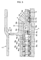
- FIGs. 2 through 4 show modified embodiments of this embodiment. Note that FIGs. 2 through 4 are schematic axial cross-sectional views of the modified embodiments of this embodiment taken along a plane inclined by 45° from the vertical direction. Note that the components of these modified embodiments that are same as those of the steam turbine 1 shown in FIG. 1 are denoted respectively by the same reference symbols and will not be described in greater detail.
- the bulkhead 9 is provided as a sealing dividing the space 10 into the inner space 10a and the outer space 10b.
- the bulkhead 9 is replaced by a nozzle box sealing device 13 as a sealing.
- the space formed around the nozzle box 5 between the turbine rotor 3 and the inner casing 2b is divided by a nozzle box sealing device 13 into the inner space 10a located inside relative to the steam passage 8 and the outer space 10b located outside relative to the steam passage 8.
- the inner space 10a means a space including an inner peripheral side (inner side) of the nozzle box 5
- the outer space 10b means a space including at least an outer peripheral side (outer side) of the nozzle box.
- the outer peripheral side of the nozzle box 5 includes outer peripheral side of the steam passage 8.
- the nozzle box sealing device 13 comprises a casing side sealing device 13a which seals a gap between the nozzle box 5 and the inner casing 2b, and a rotor side sealing device 13b which seals a gap between the nozzle box 5 and the main body of the shaft sealing device 12. Therefore, steam do not flow from the inner space 10a to the outer space 10b and vice versa.
- This arrangement provides advantages similar to those of the first embodiment of FIG. 1 .
- the nozzle box sealing device 13 comprises a packing head 13c, which seals a gap between the nozzle box 5 and the turbine rotor 3, and a groove section 13d circumferentially provided on an outer surface of the nozzle box 5 facing to the turbine rotor 3.
- the packing head 13c comprises a plurality of segments arranged in the circumferential direction inserted into the groove section 13d of the nozzle box 5 for engagement.
- the modified embodiment of FIG. 3 has two nozzle box sealing devices 13, each having a packing head 13c and a groove section 13d, that are arranged in series in the axial direction.
- the number of nozzle box sealing devices may be made one or more than two appropriately depending on the required pressure difference between the inner space 10a and the outer space 10b.
- the other modified embodiment shown in FIG. 4 further modifies the modified embodiment of FIG. 3 .
- the nozzle box 5 holds the first stage turbine nozzles 4b1 and the second stage turbine nozzles 4b2.
- the nozzle box 5 further holds the third stage turbine nozzles 4b3.
- the outer peripheral side member of the nozzle box 5 of the steam turbine extends to the downstream side in the axial direction.
- Two hook sections are provided at the extended portion, and the second stage nozzle diaphragm 4a2 and the third stage nozzle diaphragm 4a3 are engaged respectively with the two hook sections.
- a plurality of second stage turbine nozzles 4b2 and a plurality of third stage turbine nozzles 4b3 are circumferentially provided respectively with the second stage nozzle diaphragm 4a2 and the third stage nozzle diaphragm 4a3.
- the second stage turbine nozzles 4b2 and the third stage turbine nozzles 4b3 are secured to the nozzle box 5 respectively, having the second stage nozzle diaphragm 4a2 and the third stage nozzle diaphragm 4a3 therebetween.
- the configuration of this modified embodiment is the same as that of the modified embodiment of the first embodiment shown in FIG. 3 .
- the pressure of the outer space 10b of the space around the nozzle box 5 is substantially equal to the pressure of the steam passage 8 at the outlet of the third moving blade stage 3a3.
- the pressure of the outer space 10b can be further reduced, so that the wall thickness of the inner casing 2b can be reduced accordingly.
- the second and third stage nozzle diaphragms 4a2, 4a3 are arranged separately with the nozzle box 5, and the second stage and third stage turbine nozzles 4b2, 4b3 are held by the nozzle box 5 respectively by having nozzle diaphragms 4a2, 4a3 therebetween.
- the arrangement is not limited to those, and the second stage and third stage nozzle diaphragms 4a2, 4a3 may be integrally formed with the outer peripheral member of the nozzle box 5 extended to the downstream side in the axial direction.
- the fourth and the subsequent turbine nozzles 4b4, ... may also be held by the nozzle box 5.
- the nozzle box sealing device 13 including the packing head 13c and the groove section 13d is provided as a sealing for dividing the space around the nozzle box 5 into the inner space 10a and the outer space 10b in the modified embodiment of FIG. 4 .
- the nozzle box sealing device 13 may two members including a casing side sealing device 13a, which seals a gap between the nozzle box 5 and the inner casing 2b and a rotor side sealing device 13b, which seals a gap between the nozzle box 5 and the main body of the shaft sealing device 12 as shown in FIG. 2 .
- the nozzle box sealing device 13 may be replaced by a bulkhead 9 as shown in FIG. 1 .
Landscapes
- Engineering & Computer Science (AREA)
- Mechanical Engineering (AREA)
- General Engineering & Computer Science (AREA)
- Turbine Rotor Nozzle Sealing (AREA)
Applications Claiming Priority (1)
| Application Number | Priority Date | Filing Date | Title |
|---|---|---|---|
| JP2007215769A JP2009047123A (ja) | 2007-08-22 | 2007-08-22 | 蒸気タービン |
Publications (2)
| Publication Number | Publication Date |
|---|---|
| EP2028345A2 true EP2028345A2 (fr) | 2009-02-25 |
| EP2028345A3 EP2028345A3 (fr) | 2010-03-10 |
Family
ID=40084497
Family Applications (1)
| Application Number | Title | Priority Date | Filing Date |
|---|---|---|---|
| EP08014840A Withdrawn EP2028345A3 (fr) | 2007-08-22 | 2008-08-21 | Turbine à vapeur |
Country Status (5)
| Country | Link |
|---|---|
| US (1) | US8142146B2 (fr) |
| EP (1) | EP2028345A3 (fr) |
| JP (1) | JP2009047123A (fr) |
| CN (1) | CN101372896A (fr) |
| AU (1) | AU2008207424A1 (fr) |
Cited By (2)
| Publication number | Priority date | Publication date | Assignee | Title |
|---|---|---|---|---|
| EP3141708A1 (fr) * | 2015-09-08 | 2017-03-15 | General Electric Technology GmbH | Carter intérieur de turbine à vapeur avec inserts modulaires |
| US10450958B2 (en) | 2012-07-20 | 2019-10-22 | Toshiba Energy Systems & Solutions Corporation | Turbine and power generation system |
Families Citing this family (7)
| Publication number | Priority date | Publication date | Assignee | Title |
|---|---|---|---|---|
| JP2009047123A (ja) * | 2007-08-22 | 2009-03-05 | Toshiba Corp | 蒸気タービン |
| JP2009047122A (ja) * | 2007-08-22 | 2009-03-05 | Toshiba Corp | 蒸気タービン |
| JP4869370B2 (ja) * | 2009-03-13 | 2012-02-08 | 株式会社東芝 | 軸流タービンの蒸気導入部構造体および軸流タービン |
| JP5509012B2 (ja) | 2010-09-16 | 2014-06-04 | 株式会社東芝 | 蒸気タービン |
| DE102012205159A1 (de) * | 2012-03-29 | 2013-10-02 | Siemens Aktiengesellschaft | Turbinensystem mit drei an einem zentralen Getriebe angekoppelten Turbinen, Turbinenanlage und Verfahren zum Betreiben einer Arbeitsmaschine |
| JP5955345B2 (ja) * | 2014-01-27 | 2016-07-20 | 三菱日立パワーシステムズ株式会社 | 蒸気タービンを含む熱機関の流体シール構造 |
| KR101985097B1 (ko) * | 2017-10-13 | 2019-09-03 | 두산중공업 주식회사 | 가스 터빈 |
Citations (1)
| Publication number | Priority date | Publication date | Assignee | Title |
|---|---|---|---|---|
| JPH0366484A (ja) | 1989-08-02 | 1991-03-22 | Nec Corp | 電子ビーム溶接機のフィラメント電流の簡易自動校正装置 |
Family Cites Families (27)
| Publication number | Priority date | Publication date | Assignee | Title |
|---|---|---|---|---|
| DE759486C (de) * | 1941-05-04 | 1953-03-09 | Siemens Schuckertwerke A G | Fuer hohe Druecke und Temperaturen bestimmte Dampf- oder Gasturbine |
| DE846696C (de) * | 1948-11-25 | 1952-08-14 | Gutehoffnungshuette Oberhausen | Ringfoermiger Duesenkasten fuer Kreiselkraftmaschinen, insbesondere Dampf- und Gasturbinen |
| DE1004202B (de) | 1954-01-27 | 1957-03-14 | Siemens Ag | Hoechstdruck-Hoechsttemperaturturbine mit eingesetztem Innengehaeuse |
| GB790654A (en) * | 1955-07-28 | 1958-02-12 | Vickers Armstrongs Ltd | Improvements in or relating to turbines |
| FR1320174A (fr) | 1962-01-25 | 1963-03-08 | Rateau Soc | Perfectionnement des enveloppes de turbomachines, notamment de turbines à vapeur |
| GB1073415A (en) * | 1964-08-13 | 1967-06-28 | Parsons C A & Co Ltd | Improvements in and relating to steam turbines |
| BE786674A (fr) * | 1971-07-26 | 1973-01-25 | Westinghouse Electric Corp | Turbine a plusieurs enveloppes |
| JPS5338722Y2 (fr) * | 1974-11-15 | 1978-09-20 | ||
| JPS56109602U (fr) | 1980-01-24 | 1981-08-25 | ||
| US4362464A (en) * | 1980-08-22 | 1982-12-07 | Westinghouse Electric Corp. | Turbine cylinder-seal system |
| JPS58140408A (ja) * | 1982-02-17 | 1983-08-20 | Hitachi Ltd | 蒸気タ−ビンの冷却装置 |
| JPS59206602A (ja) * | 1983-05-09 | 1984-11-22 | Ishikawajima Harima Heavy Ind Co Ltd | 蒸気タ−ビン |
| JPH0621521B2 (ja) * | 1983-06-10 | 1994-03-23 | 株式会社日立製作所 | 蒸気タ−ビンの主蒸気入口構造 |
| JPS6185502A (ja) | 1984-10-03 | 1986-05-01 | Hitachi Ltd | 複流形ノズルボツクス |
| JPS61138804A (ja) * | 1984-12-10 | 1986-06-26 | Toshiba Corp | 蒸気タ−ビンの冷却装置 |
| JPH0755414B2 (ja) * | 1986-10-01 | 1995-06-14 | 株式会社東芝 | 接合ボルトおよびその締付力の調整方法 |
| DE4100777A1 (de) * | 1990-12-18 | 1992-06-25 | Asea Brown Boveri | Einlassgehaeuse fuer dampfturbine |
| US5411365A (en) * | 1993-12-03 | 1995-05-02 | General Electric Company | High pressure/intermediate pressure section divider for an opposed flow steam turbine |
| US5392513A (en) * | 1993-12-21 | 1995-02-28 | General Electric Co. | Steampath and process of retrofitting a nozzle thereof |
| JP3066484B2 (ja) | 1997-03-27 | 2000-07-17 | 工業技術院長 | 抗アレルギー剤および抗炎症剤 |
| JP3986163B2 (ja) * | 1998-06-04 | 2007-10-03 | 三菱重工業株式会社 | 蒸気タービンのノズル室暖機構造 |
| JP4095718B2 (ja) * | 1998-06-04 | 2008-06-04 | 三菱重工業株式会社 | 蒸気タービン内部のリーク低減構造 |
| CN1119505C (zh) | 1999-10-29 | 2003-08-27 | 三菱重工业株式会社 | 带有改进的外壳冷却系统的汽轮机 |
| JP4455254B2 (ja) | 2004-09-30 | 2010-04-21 | 株式会社東芝 | 蒸気タービンおよびこれを備える蒸気タービンプラント |
| JP5019601B2 (ja) | 2006-08-21 | 2012-09-05 | 株式会社東芝 | 蒸気タービン |
| JP2009047122A (ja) * | 2007-08-22 | 2009-03-05 | Toshiba Corp | 蒸気タービン |
| JP2009047123A (ja) * | 2007-08-22 | 2009-03-05 | Toshiba Corp | 蒸気タービン |
-
2007
- 2007-08-22 JP JP2007215769A patent/JP2009047123A/ja active Pending
-
2008
- 2008-08-20 AU AU2008207424A patent/AU2008207424A1/en not_active Abandoned
- 2008-08-21 US US12/195,897 patent/US8142146B2/en active Active
- 2008-08-21 CN CNA2008101308917A patent/CN101372896A/zh active Pending
- 2008-08-21 EP EP08014840A patent/EP2028345A3/fr not_active Withdrawn
Patent Citations (1)
| Publication number | Priority date | Publication date | Assignee | Title |
|---|---|---|---|---|
| JPH0366484A (ja) | 1989-08-02 | 1991-03-22 | Nec Corp | 電子ビーム溶接機のフィラメント電流の簡易自動校正装置 |
Cited By (2)
| Publication number | Priority date | Publication date | Assignee | Title |
|---|---|---|---|---|
| US10450958B2 (en) | 2012-07-20 | 2019-10-22 | Toshiba Energy Systems & Solutions Corporation | Turbine and power generation system |
| EP3141708A1 (fr) * | 2015-09-08 | 2017-03-15 | General Electric Technology GmbH | Carter intérieur de turbine à vapeur avec inserts modulaires |
Also Published As
| Publication number | Publication date |
|---|---|
| CN101372896A (zh) | 2009-02-25 |
| US8142146B2 (en) | 2012-03-27 |
| AU2008207424A1 (en) | 2009-03-12 |
| JP2009047123A (ja) | 2009-03-05 |
| EP2028345A3 (fr) | 2010-03-10 |
| US20090068001A1 (en) | 2009-03-12 |
Similar Documents
| Publication | Publication Date | Title |
|---|---|---|
| EP2028345A2 (fr) | Turbine à vapeur | |
| US8152448B2 (en) | Steam turbine having a nozzle box arranged at an upstream side of a steam passage that divides a space between a rotor and a casing into spaces that are sealed from each other | |
| EP2261468B1 (fr) | Turbine a gaz | |
| JP5791779B2 (ja) | ガスタービン | |
| EP2419609B1 (fr) | Boîtier d'une seule partie refroidie d'une turbomachine | |
| JP2009144546A (ja) | ターボチャージャ | |
| JP2011069280A (ja) | 多段ブラシシールを備えた封止機構 | |
| US8257015B2 (en) | Apparatus for cooling rotary components within a steam turbine | |
| US20180371927A1 (en) | Seal structure and turbine | |
| WO2012001995A1 (fr) | Dispositif d'étanchéité et machine fluidique comprenant celui-ci | |
| ITCO20110029A1 (it) | Girante centrifuga e turbomacchina | |
| EP2596215B1 (fr) | Ensemble d'étanchéité permettant de commander un écoulement de fluide | |
| JP2010190092A (ja) | ターボチャージャ | |
| JP2014141912A (ja) | 回転機械 | |
| CN108071492B (zh) | 燃气轮机及其预旋分流装置 | |
| US9765629B2 (en) | Method and cooling system for cooling blades of at least one blade row in a rotary flow machine | |
| US9689272B2 (en) | Gas turbine and outer shroud | |
| CN106574502B (zh) | 蒸汽轮机和用于运行蒸汽轮机的方法 | |
| JP2009191850A (ja) | 蒸気タービンエンジンとその組立方法 | |
| JP2008202419A (ja) | 蒸気タービン車室構造 | |
| CN101936194B (zh) | 具有改进的密封结构的旋转机械 | |
| US20130323009A1 (en) | Methods and apparatus for cooling rotary components within a steam turbine | |
| JP2018025125A (ja) | 過給機 | |
| JP2018021554A (ja) | ターボ過給機の軸流タービンおよびターボ過給機 | |
| JP2005194914A (ja) | シール構造及びタービンノズル |
Legal Events
| Date | Code | Title | Description |
|---|---|---|---|
| PUAI | Public reference made under article 153(3) epc to a published international application that has entered the european phase |
Free format text: ORIGINAL CODE: 0009012 |
|
| 17P | Request for examination filed |
Effective date: 20080821 |
|
| AK | Designated contracting states |
Kind code of ref document: A2 Designated state(s): AT BE BG CH CY CZ DE DK EE ES FI FR GB GR HR HU IE IS IT LI LT LU LV MC MT NL NO PL PT RO SE SI SK TR |
|
| AX | Request for extension of the european patent |
Extension state: AL BA MK RS |
|
| PUAL | Search report despatched |
Free format text: ORIGINAL CODE: 0009013 |
|
| AK | Designated contracting states |
Kind code of ref document: A3 Designated state(s): AT BE BG CH CY CZ DE DK EE ES FI FR GB GR HR HU IE IS IT LI LT LU LV MC MT NL NO PL PT RO SE SI SK TR |
|
| AX | Request for extension of the european patent |
Extension state: AL BA MK RS |
|
| RIC1 | Information provided on ipc code assigned before grant |
Ipc: F01D 9/02 20060101ALI20100203BHEP Ipc: F01D 25/26 20060101ALI20100203BHEP Ipc: F01D 9/04 20060101AFI20100203BHEP |
|
| 17Q | First examination report despatched |
Effective date: 20100602 |
|
| AKX | Designation fees paid |
Designated state(s): DE FR |
|
| STAA | Information on the status of an ep patent application or granted ep patent |
Free format text: STATUS: THE APPLICATION IS DEEMED TO BE WITHDRAWN |
|
| 18D | Application deemed to be withdrawn |
Effective date: 20101013 |