EP2028347A2 - Turbolader mit Schiebekolbenanordnung - Google Patents
Turbolader mit Schiebekolbenanordnung Download PDFInfo
- Publication number
- EP2028347A2 EP2028347A2 EP08162561A EP08162561A EP2028347A2 EP 2028347 A2 EP2028347 A2 EP 2028347A2 EP 08162561 A EP08162561 A EP 08162561A EP 08162561 A EP08162561 A EP 08162561A EP 2028347 A2 EP2028347 A2 EP 2028347A2
- Authority
- EP
- European Patent Office
- Prior art keywords
- bore
- divider
- piston
- downstream
- turbocharger
- Prior art date
- Legal status (The legal status is an assumption and is not a legal conclusion. Google has not performed a legal analysis and makes no representation as to the accuracy of the status listed.)
- Granted
Links
Images



Classifications
-
- F—MECHANICAL ENGINEERING; LIGHTING; HEATING; WEAPONS; BLASTING
- F01—MACHINES OR ENGINES IN GENERAL; ENGINE PLANTS IN GENERAL; STEAM ENGINES
- F01D—NON-POSITIVE DISPLACEMENT MACHINES OR ENGINES, e.g. STEAM TURBINES
- F01D17/00—Regulating or controlling by varying flow
- F01D17/10—Final actuators
- F01D17/12—Final actuators arranged in stator parts
- F01D17/14—Final actuators arranged in stator parts varying effective cross-sectional area of nozzles or guide conduits
- F01D17/141—Final actuators arranged in stator parts varying effective cross-sectional area of nozzles or guide conduits by means of shiftable members or valves obturating part of the flow path
- F01D17/143—Final actuators arranged in stator parts varying effective cross-sectional area of nozzles or guide conduits by means of shiftable members or valves obturating part of the flow path the shiftable member being a wall, or part thereof of a radial diffuser
-
- F—MECHANICAL ENGINEERING; LIGHTING; HEATING; WEAPONS; BLASTING
- F02—COMBUSTION ENGINES; HOT-GAS OR COMBUSTION-PRODUCT ENGINE PLANTS
- F02C—GAS-TURBINE PLANTS; AIR INTAKES FOR JET-PROPULSION PLANTS; CONTROLLING FUEL SUPPLY IN AIR-BREATHING JET-PROPULSION PLANTS
- F02C6/00—Plural gas-turbine plants; Combinations of gas-turbine plants with other apparatus; Adaptations of gas-turbine plants for special use
- F02C6/04—Gas-turbine plants providing heated or pressurised working fluid for other apparatus, e.g. without mechanical power output
- F02C6/10—Gas-turbine plants providing heated or pressurised working fluid for other apparatus, e.g. without mechanical power output supplying working fluid to a user, e.g. a chemical process, which returns working fluid to a turbine of the plant
- F02C6/12—Turbochargers, i.e. plants for augmenting mechanical power output of internal-combustion piston engines by increase of charge pressure
-
- F—MECHANICAL ENGINEERING; LIGHTING; HEATING; WEAPONS; BLASTING
- F05—INDEXING SCHEMES RELATING TO ENGINES OR PUMPS IN VARIOUS SUBCLASSES OF CLASSES F01-F04
- F05D—INDEXING SCHEME FOR ASPECTS RELATING TO NON-POSITIVE-DISPLACEMENT MACHINES OR ENGINES, GAS-TURBINES OR JET-PROPULSION PLANTS
- F05D2220/00—Application
- F05D2220/40—Application in turbochargers
Definitions
- the present invention generally relates to turbochargers with sliding piston technology. More particularly, the present invention relates to such turbochargers having a divided turbine nozzle that forms separate first-stage and second-stage nozzles for aiding in regulating the flow of exhaust gas through the turbocharger.
- Regulation of the exhaust gas flow through the turbine of an exhaust gas-driven turbocharger provides known operational advantages in terms of improved ability to control the amount of boost delivered by the turbocharger to the associated internal combustion engine.
- the regulation of exhaust gas flow is accomplished by incorporating variable geometry into the nozzle that leads into the turbine wheel. By varying the size of the nozzle flow area, the flow into the turbine wheel can be regulated, thereby regulating the overall boost provided by the turbocharger's compressor.
- Variable-geometry nozzles for turbochargers generally fall into two main categories: variable-vane nozzles, and sliding-piston nozzles. Vanes are often included in the turbine nozzle for directing the exhaust gas into the turbine in an advantageous direction. Typically a row of circumferentially spaced vanes extend axially across the nozzle. Exhaust gas from a chamber surrounding the turbine wheel flows generally radially inwardly through passages between the vanes, and the vanes turn the flow to direct the flow in a desired direction into the turbine wheel. In a variable-vane nozzle, the vanes are rotatable about their axes to vary the angle at which the vanes are set, thereby varying the flow area of the passages between the vanes.
- the nozzle may also include vanes, but the vanes are fixed in position. Variation of the nozzle flow area is accomplished by an axially sliding piston that slides in a bore in the turbine housing.
- the piston is tubular and is located just radially inwardly of the nozzle. Axial movement of the piston is effective to vary the axial extent of the nozzle opening leading into the turbine wheel.
- One type of a sliding-piston includes a divider that divides the nozzle into separate first-stage and second-stage nozzles.
- the piston When the piston is in the closed position, the piston is adjacent to the radially inner (i.e., trailing) edge of the divider, thereby effectively closing the second-stage nozzle and causing the exhaust gas to flow to the turbine wheel area via the first stage-nozzle only.
- the piston When the piston is in an open position, the gas can flow through both the first-stage and second-stage nozzles.
- variable nozzle offers the advantage of being mechanically simpler than the variable-vane nozzle.
- other drawbacks have generally been associated with sliding-piston type variable nozzles.
- the divider must be machined to precise dimensional tolerances to ensure proper sealing between the piston and the divider along a contact surface.
- the divider is relatively large, and thus a significant amount of precision machining must be performed. Further, even with precision machining, the contact surface between the piston and the divider still typically permits leakage of exhaust gas between the two members.
- the present disclosure is directed to a turbine assembly for a turbocharger, comprising a turbine housing defining a bore extending along a downstream axial direction, a chamber surrounding the bore for receiving exhaust gas, and a nozzle leading from the chamber generally radially inwardly into the bore.
- a turbine wheel is rotatably mounted in the bore and comprises a hub and a plurality of turbine blades, extending generally radially outwardly from the hub, and terminating in blade tips.
- the hub and the bore of the turbine housing are configured such that exhaust gas flowing from the nozzle to and through the turbine wheel undergoes a change in direction from a generally radially inward direction in the nozzle to the downstream axial direction downstream of the turbine wheel.
- a generally ring-shaped divider in the nozzle divides the nozzle into a first-stage nozzle and a second-stage nozzle.
- the first-stage nozzle is delimited between a fixed member of the turbine assembly and the divider.
- the divider has an upstream surface to guide exhaust gas flowing through the first-stage nozzle and an opposite downstream surface to guide exhaust gas flowing through the second-stage nozzle.
- a tubular piston is disposed in the bore of the turbine housing and is axially slidable therein.
- the piston has a radially inner surface extending along the axial direction and has a non-flat upstream end surface, with a first radius, that includes a contact region for contacting a portion of the divider with the piston in a closed position.
- the second-stage nozzle In the closed position, the second-stage nozzle is substantially closed and movement of the piston in the downstream axial direction acts to open the second-stage nozzle.
- the piston also includes a curved flow-guiding surface with a second radius proceeding from the contact region to the inner surface, the flow-guiding surface turning from a generally radially inward direction to the downstream axial direction to assist in causing the exhaust gas to execute a change in direction.
- Another aspect of the present disclosure is directed to a method for regulating gas flow to a turbocharger by providing a turbine housing defining a bore extending along a downstream axial direction, a chamber surrounding the bore for receiving exhaust gas, and a nozzle leading from the chamber generally radially inwardly into the bore.
- a generally ring-shaped divider is provided in the nozzle and divides the nozzle into first-stage and second-stage nozzles.
- the first-stage nozzle is delimited between a fixed member of the turbine assembly and the divider.
- the divider has an upstream surface to guide exhaust gas flowing through the first-stage nozzle and an opposite downstream surface to guide exhaust gas flowing through the second-stage nozzle.
- a tubular piston is also provided and disposed in the bore of the turbine housing to be axially slidable therein.
- the piston has a radially inner surface extending along the axial direction and has a non-flat upstream end surface, with a first radius, that includes a contact region for contacting a portion of the divider with the piston in a closed position. In the closed position, the second-stage nozzle is substantially closed and movement of the piston in the downstream axial direction acts to open the second-stage nozzle.
- the piston is also configured to include a curved flow-guiding surface with a second radius proceeding from the contact region to the inner surface, the flow-guiding surface turning from a generally radially inward direction to the downstream axial direction to assist in causing the exhaust gas to execute a change in direction.
- a system for a turbocharger comprises a turbine housing defining a bore extending along a downstream axial direction, a chamber surrounding the bore for receiving exhaust gas, and a nozzle leading from the chamber generally radially inwardly into the bore.
- a turbine wheel is rotatably mounted in the bore and comprises a hub and a plurality of turbine blades, extending generally radially outwardly from the hub, and terminating in blade tips.
- the hub and the bore of the turbine housing are configured such that exhaust gas flowing from the nozzle to and through the turbine wheel undergoes a change in direction from a generally radially inward direction in the nozzle to the downstream axial direction downstream of the turbine wheel.
- a generally ring-shaped divider in the nozzle divides the nozzle into a first-stage nozzle and a second-stage nozzle.
- the first-stage nozzle is delimited between a fixed member of the turbine assembly and the divider.
- the divider has an upstream surface to guide exhaust gas flowing through the first-stage nozzle and an opposite downstream surface to guide exhaust gas flowing through the second-stage nozzle.
- a tubular piston is disposed in the bore of the turbine housing and is axially slidable therein.
- the piston has a radially inner surface extending along the axial direction and has a non-flat upstream end surface, with a first radius, that includes a contact region for contacting a portion of the divider with the piston in a closed position.
- the second-stage nozzle In the closed position, the second-stage nozzle is substantially closed and movement of the piston in the downstream axial direction acts to open the second-stage nozzle.
- the piston also includes a curved flow-guiding surface with a second radius proceeding from the contact region to the inner surface, the flow-guiding surface turning from a generally radially inward direction to the downstream axial direction to assist in causing the exhaust gas to execute a change in direction.
- FIG. 1 is a cross-sectional view of a turbocharger in accordance with one embodiment of the invention, showing the piston in an open position;
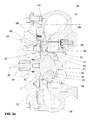
- FIG. 2a is a view similar to FIG. 1 , with the piston in a closed position;
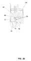
- FIG. 2b is an enlarged view of the divider and a portion of the piston assembly of Figure 2a .
- FIG. 3 is an enlarged view of the divider and a portion of the piston assembly illustrating a second embodiment of the second-stage nozzle.
- FIG. 4 is an enlarged view of the divider and a portion of the piston assembly illustrating a third embodiment of the second-stage nozzle.
- FIG. 5 is an enlarged view of the divider and a portion of the piston assembly illustrating a fourth embodiment of the second-stage nozzle.
- FIGS. 1 through 5 A turbocharger 20 in accordance with the invention is shown in FIGS. 1 through 5 .
- the turbocharger includes a center housing 22 that contains a rotary shaft 26 of the turbocharger 20.
- a compressor housing (not shown) is coupled to one side of the center housing.
- a compressor wheel is mounted on one end of the shaft 26 and is disposed in the compressor housing.
- the compressor housing defines an inlet through which air is drawn into the compressor wheel, which compresses the air, and further defines a diffuser through which the compressed air is discharged from the compressor wheel into a volute surrounding the compressor wheel. From the volute, the air is delivered to the intake of an internal combustion engine (not shown).
- the turbocharger further comprises a turbine housing 38 coupled to the opposite side of the center housing 22 .
- a turbine wheel 40 is mounted on the opposite end of the shaft 26 from the compressor wheel and is disposed in the turbine housing 38 .
- the turbine housing 38 defines a chamber 42 that surrounds the turbine wheel 40 and receives exhaust gas from the internal combustion engine. Exhaust gas is directed from the chamber 42 through a first-stage nozzle 65 and optionally second-stage nozzle 70 ( FIGS. 1-5 ) into the turbine wheel 40 , which expands the exhaust gas and is driven thereby so as to drive the compressor wheel.
- the turbine housing 38 defines a generally cylindrical axial bore 50 whose diameter generally corresponds to a radially innermost extent of the chamber 42.
- the turbine wheel 40 resides in an upstream end of the bore 50 and includes a hub 41.
- the rotational axis for both the turbine wheel 40 and the hub 41 is substantially coaxial with the bore 50 .
- upstream in this context refers to the direction of exhaust gas flow through the bore 50, as the exhaust gas in the chamber 42 flows into the turbine wheel 40 and is then turned to flow generally axially (left to right in FIG. 1 ) through the bore 50 to its downstream end.
- the turbine wheel 40 comprises a number of turbine blades 43 joined to the hub 41 and extending in a generally radial direction from the axis of the turbine wheel 40.
- the turbine blades 43 terminate at a radially outermost point to form turbine blade tips 44.
- the turbocharger 20 includes a tubular piston 62 that resides in the bore 50 of the turbine housing 38 .
- a seal ring 64 Surrounding tubular piston 62 is a seal ring 64 that contacts an inner surface of a tubular carrier 52 mounted in the bore 50 to prevent the escape of exhaust gases between the tubular piston 62 and carrier 52 .
- the outer diameter of tubular piston 62 is slightly smaller than the inner diameter of the carrier 52 such that the piston 62 can be slid axially back and forth relative to the fixed carrier 52.
- the piston 62 is axially slidable between an open position as shown in FIG. 1 wherein the piston 62 is spaced from a divider 68 , a closed position as shown in FIG. 2 wherein the piston 62 abuts a downstream surface 69 of the divider 68 , and various partially open positions therebetween.
- the closed position FIG. 2
- the size of the total nozzle area through which exhaust gas flows from the chamber 42 to the turbine wheel 40 is at a minimum and the exhaust gas is constrained to flow through the row of vanes 58 of the first-stage nozzle 65 and along a divider upstream surface 67 .
- the open position of the piston 62 FIG.
- the nozzle flow area is at a maximum and part of the gas flows through the vanes 58 of the first-stage nozzle 65 while additional flow passes through second-stage nozzle 70 .
- the second-stage nozzle 70 can also include vanes 66, with openings between the vanes 66, defined in the upstream end of the piston 62.
- the second-stage nozzle 70 is essentially defined in the upstream direction by divider 68 and in the downstream direction along the piston 62 .
- the portions of the divider 68 within the second-stage nozzle 70 are the downstream surface 69 and radially innermost edge 71, whereas the portions of the piston 62 within the second-stage nozzle 70 are the non-flat upstream surface 63 and the flow guiding surface 72.
- the downstream surface 69 is essentially complementary with the non-flat upstream surface 63 and the flow guiding surface 72 to direct the flow of the exhaust gas through the second-stage nozzle 70 in an optimal direction to engage the turbine blades 43 of the turbine wheel 40.
- the turbine blade tips 44 in a radial-axial projection form a contour that is near the second-stage nozzle 70 and is at least somewhat complementary to a curved flow-guiding surface 72 of the piston 62 .
- the complementary shaping of the flow-guiding surface 72 assists in altering the direction of exhaust gas from a generally radially inward direction in the first-stage and second-stage nozzles 65/70 to an axial direction downstream of the turbine wheel 40 and parallel with a radially-inner surface 61 of the piston 62 .
- Such a configuration aids in increasing the efficiency of the turbocharger 20.
- the piston 62 is slid axially in an upstream direction such that the non-flat upstream surface 63 and the flow guiding surface 72 of the piston 62 abut against the downstream surface 69 of the divider 68 ( FIGS. 2a-b ).
- the downstream surface 69 is essentially complementary with the non-flat upstream surface 63 and the flow guiding surface 72 , an effective seal is formed.
- the seal formed between the surfaces of the divider 68 and the piston 62 effectively reduce or eliminate the flow of exhaust gas through the second-stage nozzle 70.
- An effective seal can be formed between the divider 68 and the piston 62 to effectively close the second-stage nozzle through a variety of other surface shapes along the downstream surface 69 of the divider 68 and the non-flat upstream surface 63 of the piston 62 .
- non-flat upstream surface 63 of the piston 62 may retain the same shape as illustrated in FIGS. 2a-b while the downstream surface 69 of the divider may form a generally flat surface with a negative slope. In this configuration, downstream surface 69 gradually moves in the upstream direction as the divider 68 extends toward the axis of the bore 50 ( FIG. 3 ).
- the non-flat-upstream surface 63 may include a boss.
- the boss itself can be formed along the non-flat-upstream surface 63 at a number of positions and the boss may have varying degrees of protrusion.
- Figure 4 illustrates a non-flat-upstream surface 63 of the piston that includes a small boss. Where a small boss in present on the non-flat-upstream surface 63 , the downstream surface 69 of the divider 68 may include a shape that is complementary to at least a portion of the boss ( FIG. 4 ).
- Figure 5 illustrates a non-flat-upstream surface 63 the piston 62 that includes a large boss.
Landscapes
- Engineering & Computer Science (AREA)
- Mechanical Engineering (AREA)
- General Engineering & Computer Science (AREA)
- Chemical & Material Sciences (AREA)
- Chemical Kinetics & Catalysis (AREA)
- General Chemical & Material Sciences (AREA)
- Combustion & Propulsion (AREA)
- Supercharger (AREA)
Applications Claiming Priority (1)
| Application Number | Priority Date | Filing Date | Title |
|---|---|---|---|
| US11/842,310 US7762067B2 (en) | 2007-08-21 | 2007-08-21 | Turbocharger with sliding piston assembly |
Publications (3)
| Publication Number | Publication Date |
|---|---|
| EP2028347A2 true EP2028347A2 (de) | 2009-02-25 |
| EP2028347A3 EP2028347A3 (de) | 2014-06-04 |
| EP2028347B1 EP2028347B1 (de) | 2015-03-18 |
Family
ID=39797450
Family Applications (1)
| Application Number | Title | Priority Date | Filing Date |
|---|---|---|---|
| EP08162561.8A Not-in-force EP2028347B1 (de) | 2007-08-21 | 2008-08-18 | Turbolader mit Schiebekolbenanordnung |
Country Status (3)
| Country | Link |
|---|---|
| US (1) | US7762067B2 (de) |
| EP (1) | EP2028347B1 (de) |
| CN (1) | CN101372899B (de) |
Cited By (1)
| Publication number | Priority date | Publication date | Assignee | Title |
|---|---|---|---|---|
| EP2067962A3 (de) * | 2007-12-05 | 2011-06-29 | Bosch Mahle Turbo Systems GmbH & Co. KG | Turbine eines Abgasturboladers einer Brennkraftmaschine |
Families Citing this family (7)
| Publication number | Priority date | Publication date | Assignee | Title |
|---|---|---|---|---|
| US8047772B2 (en) * | 2005-03-30 | 2011-11-01 | Honeywell International Inc. | Variable geometry turbine for a turbocharger and method of controlling the turbine |
| EP1866534B1 (de) * | 2005-04-04 | 2008-09-24 | Honeywell International Inc. | Turbolader mit variabler strömung |
| EP1957757B1 (de) * | 2005-11-16 | 2013-02-13 | Honeywell International Inc. | Turbolader mit axialem Ringschiebereinsatz |
| CN203978601U (zh) * | 2014-08-13 | 2014-12-03 | 安徽江淮汽车股份有限公司 | 增压器及汽车 |
| CN110608091A (zh) * | 2018-06-14 | 2019-12-24 | 博格华纳公司 | 用于具有可变调节机构的压缩机的装置 |
| US10487681B1 (en) | 2018-08-07 | 2019-11-26 | Eyal Ezra | Variable geometry turbocharger adjustment device |
| DE202021106090U1 (de) * | 2021-11-08 | 2023-02-09 | BorgWarner Inc. | Turbinengehäuse für einen Abgasturbolader |
Family Cites Families (22)
| Publication number | Priority date | Publication date | Assignee | Title |
|---|---|---|---|---|
| NL98031C (de) * | 1957-12-23 | |||
| US2957424A (en) * | 1958-11-19 | 1960-10-25 | Gen Motors Corp | Centrifugal pump |
| BE793550A (fr) * | 1971-12-29 | 1973-04-16 | Gen Electric | Pompe centrifuge a diffuseur reglable |
| US4499731A (en) * | 1981-12-09 | 1985-02-19 | Bbc Brown, Boveri & Company, Limited | Controllable exhaust gas turbocharger |
| US4776168A (en) * | 1987-05-21 | 1988-10-11 | Woollenweber William E | Variable geometry turbocharger turbine |
| US4802817A (en) * | 1987-12-23 | 1989-02-07 | Sundstrand Corporation | Centrifugal pump with self-regulating impeller discharge shutter |
| DE4204019A1 (de) * | 1992-02-12 | 1993-05-27 | Daimler Benz Ag | Gesteuerte abgasturboladerturbine fuer einen verbrennungsmotor |
| EP0571205B1 (de) * | 1992-05-21 | 1997-03-05 | Alliedsignal Limited | Regelbarer Turbolader |
| DE4303520C1 (de) * | 1993-02-06 | 1994-09-22 | Daimler Benz Ag | Verstellbarer Strömungsleitapparat für eine Abgasturbine |
| DE4303521C1 (de) * | 1993-02-06 | 1994-01-05 | Daimler Benz Ag | Verstellbarer Strömungsleitapparat für eine Abgasturbine |
| US6715288B1 (en) * | 1999-05-27 | 2004-04-06 | Borgwarner, Inc. | Controllable exhaust gas turbocharger with a double-fluted turbine housing |
| DE60010756T2 (de) * | 2000-01-14 | 2005-05-12 | Honeywell Garrett S.A. | Turbolader mit verschiebbaren leitschaufeln, hitzeschild und einer abnehmbaren, axialen betätigungsvorrichtung |
| DE10029807C1 (de) * | 2000-06-16 | 2002-03-21 | Daimler Chrysler Ag | Abgasturbolader für eine Brennkraftmaschine |
| AU2001221812A1 (en) * | 2000-11-30 | 2002-06-11 | Honeywell Garrett Sa | Variable geometry turbocharger with sliding piston |
| ITTO20010506A1 (it) * | 2001-05-25 | 2002-11-25 | Iveco Motorenforschung Ag | Turbina a geometria variabile. |
| GB0121864D0 (en) * | 2001-09-10 | 2001-10-31 | Leavesley Malcolm G | Turbocharger apparatus |
| GB2392956A (en) * | 2002-09-12 | 2004-03-17 | Honeywell Uk Ltd | Controlling inlet to turbocharger turbine |
| JP2005539177A (ja) * | 2002-09-18 | 2005-12-22 | ハネウェル・インターナショナル・インコーポレーテッド | ターボチャージャのための可変ノズル装置及び同装置の作動方法 |
| US7010918B2 (en) * | 2003-06-17 | 2006-03-14 | Daimlerchrysler Ag | Internal combustion engine with motor brake |
| US7581394B2 (en) * | 2003-12-10 | 2009-09-01 | Honeywell International Inc. | Variable nozzle device for a turbocharger |
| EP1948909A1 (de) * | 2005-11-16 | 2008-07-30 | Honeywell International Inc. | Turbolader mit verstellbarer kolbenartiger düse mit integriertem betätigungssystem |
| EP1957757B1 (de) * | 2005-11-16 | 2013-02-13 | Honeywell International Inc. | Turbolader mit axialem Ringschiebereinsatz |
-
2007
- 2007-08-21 US US11/842,310 patent/US7762067B2/en not_active Expired - Fee Related
-
2008
- 2008-08-18 EP EP08162561.8A patent/EP2028347B1/de not_active Not-in-force
- 2008-08-20 CN CN2008101611933A patent/CN101372899B/zh not_active Expired - Fee Related
Cited By (1)
| Publication number | Priority date | Publication date | Assignee | Title |
|---|---|---|---|---|
| EP2067962A3 (de) * | 2007-12-05 | 2011-06-29 | Bosch Mahle Turbo Systems GmbH & Co. KG | Turbine eines Abgasturboladers einer Brennkraftmaschine |
Also Published As
| Publication number | Publication date |
|---|---|
| US7762067B2 (en) | 2010-07-27 |
| US20090049834A1 (en) | 2009-02-26 |
| CN101372899A (zh) | 2009-02-25 |
| EP2028347A3 (de) | 2014-06-04 |
| EP2028347B1 (de) | 2015-03-18 |
| CN101372899B (zh) | 2013-12-04 |
Similar Documents
| Publication | Publication Date | Title |
|---|---|---|
| EP2028347B1 (de) | Turbolader mit Schiebekolbenanordnung | |
| US8113770B2 (en) | Turbine assembly for an exhaust gas-driven turbocharger having a variable nozzle | |
| KR102076638B1 (ko) | 가변 터빈 구조를 구비한 혼류 터보차저 | |
| US10227917B2 (en) | Passive inlet-adjustment mechanisms for compressor, and turbocharger having same | |
| EP1714008B1 (de) | Abgasturbolader | |
| US8123470B2 (en) | Turbine assembly with semi-divided nozzle and half-collar piston | |
| US7828517B2 (en) | Variable-geometry turbocharger with asymmetric divided volute for engine exhaust gas pulse optimization | |
| EP1584796B1 (de) | Turbine mit variabler Geometrie | |
| US10900415B2 (en) | Turbocharger having a meridionally divided turbine housing and a variable turbine nozzle | |
| US7870731B2 (en) | Exhaust gas turbocharger for an internal combustion engine | |
| KR101905792B1 (ko) | 펄스 분리형 가변 터빈 구조 터보차저를 위한 카트리지 | |
| EP1957757B1 (de) | Turbolader mit axialem Ringschiebereinsatz | |
| CN111148903A (zh) | 用于内燃发动机的增压装置的具有虹膜式隔板机构的径流式压缩机、增压装置和虹膜式隔板机构的叶片 | |
| EP1866534B1 (de) | Turbolader mit variabler strömung | |
| US8197195B2 (en) | Turbocharger with stepped two-stage vane nozzle | |
| US8112995B2 (en) | Turbocharger with variable turbine geometry | |
| CN108487941B (zh) | 一种涡轮增压器锥形可变喷嘴组件 | |
| CN108442981B (zh) | 一种双活塞环可变喷嘴组件 | |
| CN108361077B (zh) | 一种可变喷嘴组件的倾斜渐缩的喷嘴叶片结构 |
Legal Events
| Date | Code | Title | Description |
|---|---|---|---|
| PUAI | Public reference made under article 153(3) epc to a published international application that has entered the european phase |
Free format text: ORIGINAL CODE: 0009012 |
|
| 17P | Request for examination filed |
Effective date: 20080818 |
|
| AK | Designated contracting states |
Kind code of ref document: A2 Designated state(s): AT BE BG CH CY CZ DE DK EE ES FI FR GB GR HR HU IE IS IT LI LT LU LV MC MT NL NO PL PT RO SE SI SK TR |
|
| AX | Request for extension of the european patent |
Extension state: AL BA MK RS |
|
| PUAL | Search report despatched |
Free format text: ORIGINAL CODE: 0009013 |
|
| AK | Designated contracting states |
Kind code of ref document: A3 Designated state(s): AT BE BG CH CY CZ DE DK EE ES FI FR GB GR HR HU IE IS IT LI LT LU LV MC MT NL NO PL PT RO SE SI SK TR |
|
| AX | Request for extension of the european patent |
Extension state: AL BA MK RS |
|
| RIC1 | Information provided on ipc code assigned before grant |
Ipc: F01D 17/14 20060101AFI20140430BHEP Ipc: F02C 6/12 20060101ALI20140430BHEP |
|
| 17Q | First examination report despatched |
Effective date: 20140521 |
|
| GRAJ | Information related to disapproval of communication of intention to grant by the applicant or resumption of examination proceedings by the epo deleted |
Free format text: ORIGINAL CODE: EPIDOSDIGR1 |
|
| GRAP | Despatch of communication of intention to grant a patent |
Free format text: ORIGINAL CODE: EPIDOSNIGR1 |
|
| GRAP | Despatch of communication of intention to grant a patent |
Free format text: ORIGINAL CODE: EPIDOSNIGR1 |
|
| INTG | Intention to grant announced |
Effective date: 20141104 |
|
| GRAS | Grant fee paid |
Free format text: ORIGINAL CODE: EPIDOSNIGR3 |
|
| AKX | Designation fees paid |
Designated state(s): DE FR GB |
|
| GRAA | (expected) grant |
Free format text: ORIGINAL CODE: 0009210 |
|
| AK | Designated contracting states |
Kind code of ref document: B1 Designated state(s): DE FR GB |
|
| REG | Reference to a national code |
Ref country code: GB Ref legal event code: FG4D |
|
| REG | Reference to a national code |
Ref country code: DE Ref legal event code: R096 Ref document number: 602008037173 Country of ref document: DE Effective date: 20150430 |
|
| REG | Reference to a national code |
Ref country code: FR Ref legal event code: PLFP Year of fee payment: 8 |
|
| RAP2 | Party data changed (patent owner data changed or rights of a patent transferred) |
Owner name: HONEYWELL INTERNATIONAL INC. |
|
| REG | Reference to a national code |
Ref country code: DE Ref legal event code: R097 Ref document number: 602008037173 Country of ref document: DE |
|
| PLBE | No opposition filed within time limit |
Free format text: ORIGINAL CODE: 0009261 |
|
| STAA | Information on the status of an ep patent application or granted ep patent |
Free format text: STATUS: NO OPPOSITION FILED WITHIN TIME LIMIT |
|
| 26N | No opposition filed |
Effective date: 20151221 |
|
| REG | Reference to a national code |
Ref country code: FR Ref legal event code: PLFP Year of fee payment: 9 |
|
| REG | Reference to a national code |
Ref country code: FR Ref legal event code: PLFP Year of fee payment: 10 |
|
| REG | Reference to a national code |
Ref country code: FR Ref legal event code: PLFP Year of fee payment: 11 |
|
| REG | Reference to a national code |
Ref country code: DE Ref legal event code: R081 Ref document number: 602008037173 Country of ref document: DE Owner name: GARRETT TRANSPORTATION I INC., TORRANCE, US Free format text: FORMER OWNER: HONEYWELL INTERNATIONAL INC., MORRISTOWN, N.J., US |
|
| REG | Reference to a national code |
Ref country code: GB Ref legal event code: 732E Free format text: REGISTERED BETWEEN 20190725 AND 20190731 |
|
| PGFP | Annual fee paid to national office [announced via postgrant information from national office to epo] |
Ref country code: FR Payment date: 20190827 Year of fee payment: 12 Ref country code: DE Payment date: 20190830 Year of fee payment: 12 |
|
| PGFP | Annual fee paid to national office [announced via postgrant information from national office to epo] |
Ref country code: GB Payment date: 20190829 Year of fee payment: 12 |
|
| REG | Reference to a national code |
Ref country code: DE Ref legal event code: R119 Ref document number: 602008037173 Country of ref document: DE |
|
| GBPC | Gb: european patent ceased through non-payment of renewal fee |
Effective date: 20200818 |
|
| PG25 | Lapsed in a contracting state [announced via postgrant information from national office to epo] |
Ref country code: DE Free format text: LAPSE BECAUSE OF NON-PAYMENT OF DUE FEES Effective date: 20210302 Ref country code: FR Free format text: LAPSE BECAUSE OF NON-PAYMENT OF DUE FEES Effective date: 20200831 |
|
| PG25 | Lapsed in a contracting state [announced via postgrant information from national office to epo] |
Ref country code: GB Free format text: LAPSE BECAUSE OF NON-PAYMENT OF DUE FEES Effective date: 20200818 |