EP2028396A2 - Transmission - Google Patents
Transmission Download PDFInfo
- Publication number
- EP2028396A2 EP2028396A2 EP08153155A EP08153155A EP2028396A2 EP 2028396 A2 EP2028396 A2 EP 2028396A2 EP 08153155 A EP08153155 A EP 08153155A EP 08153155 A EP08153155 A EP 08153155A EP 2028396 A2 EP2028396 A2 EP 2028396A2
- Authority
- EP
- European Patent Office
- Prior art keywords
- shift
- shifting
- claw portion
- moved
- lug
- Prior art date
- Legal status (The legal status is an assumption and is not a legal conclusion. Google has not performed a legal analysis and makes no representation as to the accuracy of the status listed.)
- Granted
Links
Images





Classifications
-
- F—MECHANICAL ENGINEERING; LIGHTING; HEATING; WEAPONS; BLASTING
- F16—ENGINEERING ELEMENTS AND UNITS; GENERAL MEASURES FOR PRODUCING AND MAINTAINING EFFECTIVE FUNCTIONING OF MACHINES OR INSTALLATIONS; THERMAL INSULATION IN GENERAL
- F16H—GEARING
- F16H63/00—Control outputs from the control unit to change-speed- or reversing-gearings for conveying rotary motion or to other devices than the final output mechanism
- F16H63/02—Final output mechanisms therefor; Actuating means for the final output mechanisms
- F16H63/30—Constructional features of the final output mechanisms
-
- F—MECHANICAL ENGINEERING; LIGHTING; HEATING; WEAPONS; BLASTING
- F16—ENGINEERING ELEMENTS AND UNITS; GENERAL MEASURES FOR PRODUCING AND MAINTAINING EFFECTIVE FUNCTIONING OF MACHINES OR INSTALLATIONS; THERMAL INSULATION IN GENERAL
- F16H—GEARING
- F16H61/00—Control functions within control units of change-speed- or reversing-gearings for conveying rotary motion ; Control of exclusively fluid gearing, friction gearing, gearings with endless flexible members or other particular types of gearing
- F16H61/68—Control functions within control units of change-speed- or reversing-gearings for conveying rotary motion ; Control of exclusively fluid gearing, friction gearing, gearings with endless flexible members or other particular types of gearing specially adapted for stepped gearings
- F16H61/684—Control functions within control units of change-speed- or reversing-gearings for conveying rotary motion ; Control of exclusively fluid gearing, friction gearing, gearings with endless flexible members or other particular types of gearing specially adapted for stepped gearings without interruption of drive
- F16H61/688—Control functions within control units of change-speed- or reversing-gearings for conveying rotary motion ; Control of exclusively fluid gearing, friction gearing, gearings with endless flexible members or other particular types of gearing specially adapted for stepped gearings without interruption of drive with two inputs, e.g. selection of one of two torque-flow paths by clutches
-
- F—MECHANICAL ENGINEERING; LIGHTING; HEATING; WEAPONS; BLASTING
- F16—ENGINEERING ELEMENTS AND UNITS; GENERAL MEASURES FOR PRODUCING AND MAINTAINING EFFECTIVE FUNCTIONING OF MACHINES OR INSTALLATIONS; THERMAL INSULATION IN GENERAL
- F16H—GEARING
- F16H63/00—Control outputs from the control unit to change-speed- or reversing-gearings for conveying rotary motion or to other devices than the final output mechanism
- F16H63/02—Final output mechanisms therefor; Actuating means for the final output mechanisms
- F16H63/08—Multiple final output mechanisms being moved by a single common final actuating mechanism
- F16H63/20—Multiple final output mechanisms being moved by a single common final actuating mechanism with preselection and subsequent movement of each final output mechanism by movement of the final actuating mechanism in two different ways, e.g. guided by a shift gate
-
- F—MECHANICAL ENGINEERING; LIGHTING; HEATING; WEAPONS; BLASTING
- F16—ENGINEERING ELEMENTS AND UNITS; GENERAL MEASURES FOR PRODUCING AND MAINTAINING EFFECTIVE FUNCTIONING OF MACHINES OR INSTALLATIONS; THERMAL INSULATION IN GENERAL
- F16H—GEARING
- F16H63/00—Control outputs from the control unit to change-speed- or reversing-gearings for conveying rotary motion or to other devices than the final output mechanism
- F16H63/02—Final output mechanisms therefor; Actuating means for the final output mechanisms
- F16H63/08—Multiple final output mechanisms being moved by a single common final actuating mechanism
- F16H63/20—Multiple final output mechanisms being moved by a single common final actuating mechanism with preselection and subsequent movement of each final output mechanism by movement of the final actuating mechanism in two different ways, e.g. guided by a shift gate
- F16H63/22—Multiple final output mechanisms being moved by a single common final actuating mechanism with preselection and subsequent movement of each final output mechanism by movement of the final actuating mechanism in two different ways, e.g. guided by a shift gate the final output mechanisms being simultaneously moved by the final actuating mechanism
-
- F—MECHANICAL ENGINEERING; LIGHTING; HEATING; WEAPONS; BLASTING
- F16—ENGINEERING ELEMENTS AND UNITS; GENERAL MEASURES FOR PRODUCING AND MAINTAINING EFFECTIVE FUNCTIONING OF MACHINES OR INSTALLATIONS; THERMAL INSULATION IN GENERAL
- F16H—GEARING
- F16H63/00—Control outputs from the control unit to change-speed- or reversing-gearings for conveying rotary motion or to other devices than the final output mechanism
- F16H63/02—Final output mechanisms therefor; Actuating means for the final output mechanisms
- F16H63/24—Final output mechanisms therefor; Actuating means for the final output mechanisms each of the final output mechanisms being moved by only one of the various final actuating mechanisms
- F16H63/26—Final output mechanisms therefor; Actuating means for the final output mechanisms each of the final output mechanisms being moved by only one of the various final actuating mechanisms some of the movements of the final output mechanisms being caused by another final output mechanism
-
- F—MECHANICAL ENGINEERING; LIGHTING; HEATING; WEAPONS; BLASTING
- F16—ENGINEERING ELEMENTS AND UNITS; GENERAL MEASURES FOR PRODUCING AND MAINTAINING EFFECTIVE FUNCTIONING OF MACHINES OR INSTALLATIONS; THERMAL INSULATION IN GENERAL
- F16H—GEARING
- F16H63/00—Control outputs from the control unit to change-speed- or reversing-gearings for conveying rotary motion or to other devices than the final output mechanism
- F16H63/02—Final output mechanisms therefor; Actuating means for the final output mechanisms
- F16H2063/025—Final output mechanisms for double clutch transmissions
-
- F—MECHANICAL ENGINEERING; LIGHTING; HEATING; WEAPONS; BLASTING
- F16—ENGINEERING ELEMENTS AND UNITS; GENERAL MEASURES FOR PRODUCING AND MAINTAINING EFFECTIVE FUNCTIONING OF MACHINES OR INSTALLATIONS; THERMAL INSULATION IN GENERAL
- F16H—GEARING
- F16H63/00—Control outputs from the control unit to change-speed- or reversing-gearings for conveying rotary motion or to other devices than the final output mechanism
- F16H63/02—Final output mechanisms therefor; Actuating means for the final output mechanisms
- F16H63/08—Multiple final output mechanisms being moved by a single common final actuating mechanism
- F16H63/20—Multiple final output mechanisms being moved by a single common final actuating mechanism with preselection and subsequent movement of each final output mechanism by movement of the final actuating mechanism in two different ways, e.g. guided by a shift gate
- F16H2063/208—Multiple final output mechanisms being moved by a single common final actuating mechanism with preselection and subsequent movement of each final output mechanism by movement of the final actuating mechanism in two different ways, e.g. guided by a shift gate using two or more selecting fingers
-
- F—MECHANICAL ENGINEERING; LIGHTING; HEATING; WEAPONS; BLASTING
- F16—ENGINEERING ELEMENTS AND UNITS; GENERAL MEASURES FOR PRODUCING AND MAINTAINING EFFECTIVE FUNCTIONING OF MACHINES OR INSTALLATIONS; THERMAL INSULATION IN GENERAL
- F16H—GEARING
- F16H2200/00—Transmissions for multiple ratios
- F16H2200/003—Transmissions for multiple ratios characterised by the number of forward speeds
- F16H2200/0052—Transmissions for multiple ratios characterised by the number of forward speeds the gear ratios comprising six forward speeds
-
- Y—GENERAL TAGGING OF NEW TECHNOLOGICAL DEVELOPMENTS; GENERAL TAGGING OF CROSS-SECTIONAL TECHNOLOGIES SPANNING OVER SEVERAL SECTIONS OF THE IPC; TECHNICAL SUBJECTS COVERED BY FORMER USPC CROSS-REFERENCE ART COLLECTIONS [XRACs] AND DIGESTS
- Y10—TECHNICAL SUBJECTS COVERED BY FORMER USPC
- Y10S—TECHNICAL SUBJECTS COVERED BY FORMER USPC CROSS-REFERENCE ART COLLECTIONS [XRACs] AND DIGESTS
- Y10S74/00—Machine element or mechanism
- Y10S74/90—Particular shift pattern
-
- Y—GENERAL TAGGING OF NEW TECHNOLOGICAL DEVELOPMENTS; GENERAL TAGGING OF CROSS-SECTIONAL TECHNOLOGIES SPANNING OVER SEVERAL SECTIONS OF THE IPC; TECHNICAL SUBJECTS COVERED BY FORMER USPC CROSS-REFERENCE ART COLLECTIONS [XRACs] AND DIGESTS
- Y10—TECHNICAL SUBJECTS COVERED BY FORMER USPC
- Y10T—TECHNICAL SUBJECTS COVERED BY FORMER US CLASSIFICATION
- Y10T74/00—Machine element or mechanism
- Y10T74/19—Gearing
- Y10T74/19219—Interchangeably locked
- Y10T74/19251—Control mechanism
-
- Y—GENERAL TAGGING OF NEW TECHNOLOGICAL DEVELOPMENTS; GENERAL TAGGING OF CROSS-SECTIONAL TECHNOLOGIES SPANNING OVER SEVERAL SECTIONS OF THE IPC; TECHNICAL SUBJECTS COVERED BY FORMER USPC CROSS-REFERENCE ART COLLECTIONS [XRACs] AND DIGESTS
- Y10—TECHNICAL SUBJECTS COVERED BY FORMER USPC
- Y10T—TECHNICAL SUBJECTS COVERED BY FORMER US CLASSIFICATION
- Y10T74/00—Machine element or mechanism
- Y10T74/20—Control lever and linkage systems
- Y10T74/20012—Multiple controlled elements
- Y10T74/20018—Transmission control
- Y10T74/20177—Particular element [e.g., shift fork, template, etc.]
Definitions
- the present invention relates to a mechanical transmission, and more particularly to the construction of a transmission unit of a transmission which includes dual clutches.
- the transmission includes a shift shaft which can be moved in a shifting direction and a selecting direction through sliding and rotating, a plurality of shift lugs (shift brackets) which are arranged in the selecting direction, and shift rails (rods) which connect the shift lugs and shift forks, respectively.
- a shift member which is formed into a pawl shape, is provided on the shift shaft in such a manner as to project outwards, and a pair of claw portions is provided on each shift lug in such a manner as to be spaced apart from each other in the shifting direction.
- the shift shaft is moved by the actuator in the mechanical automatic transmission, whereby the claw portion of the shift lug is selectively pushed to be moved in the shifting direction by the shift member, so that the shift fork is operated to be moved selectively.
- dual clutch type automatic transmissions having two clutches have been developed.
- a target gear is engaged via the other clutch, and when the rotational speed of the target gear comes to synchronize with that of the gear engaged via the one clutch, the one clutch is disengaged, whereby no neutral state takes place during the gearchange, and a gearchange is enabled in which there is virtually no interruption of power flow as the gearchange takes places.
- Fig. 8 is a schematic diagram showing the construction of a shift mechanism of a shift lug according to the related art ( JP-A-2001-304411 ).
- a construction is adopted in which a shift member 71 is caused to swing by rotation of a control shaft 70 so as to push a claw portion 73 of a shift lug 72 in a shifting direction.
- the shift member 71 is caused to push the claw portion 73 while the shift member 71 is tilted largely towards the shifting direction.
- a force exerted on the claw portion 73 by a rotational torque T of the control shaft 70 then is a tangential force F
- a distance from a contact point a between the shift member 71 and the claw portion 73 to an axial center C of the control shaft 70 is a distance L2
- a tilt angle of a line which connects the contact point a with the axial center C towards the shifting direction is an angle ⁇
- a component of the tangential force F in the shifting direction that is, a component force P1 which is a force which shifts the shift lug 72 in the shifting direction is obtained by the following equation (1).
- a transmission comprising:
- a pressing portion via which the shift member pushes the first claw portion is provided on the predetermined shift lug, an abutment portion via which the shift member is brought into abutment with the second claw portion is provided on the predetermined shift lug.
- the pressing portion and the abutment portion may be offset from each other in the shifting direction.
- a pressing portion provided on the shift lug which is in the neutral position and the abutment portion provided on the predetermined shift lug which is in the shifting position may be disposed on the same plane with respect to the shifting direction.
- the transmission may further include: a shaft, extended in the selecting direction, and adapted to be moved in the selecting direction and rotated, by the actuator.
- the shift member may project from an outer circumference of the shaft.
- a plurality of the shift member may be provided on the shaft and be spaced apart from each other in the selecting direction.
- a transmission comprising:
- Fig. 1 is an exemplary diagram of a transmission unit 1 of a dual clutch type transmission with six forward gears and one reverse gear to which the invention is applied.
- the transmission unit 1 includes two clutches 2, 3, two main shafts 4, 5 which are disposed concentrically and two counter shafts 6, 7. Power is configured to be delivered to the first main shaft 4 from an output shaft 9 of an engine 8 via the first clutch 2, while the power is configured to be delivered to the second main shaft 5 from the output shaft 9 via the second clutch 3.
- the first counter shaft 6 and the second counter shaft 7 are disposed spaced apart in such a manner that their axes become parallel to those of the first main shaft 4 and the second main shaft 5 and are configured to be able to deliver the power to a differential 10 which is disposed at a final stage of the transmission unit 1.
- a first speed gear 11, a second speed gear 12, a third speed gear 13 and a sixth speed gear 14 are pivotally supported on the first counter shaft 6 in such a manner as to rotate thereon.
- a fourth speed gear 15, a fifth speed gear 16 and a reverse gear 17 are pivotally supported on the second counter shaft 7 in such a manner as to rotate thereon, and a parking gear 18 is fixed to the second counter shaft 7.
- shift forks 20 to 23 are provided in the transmission unit 1.
- a first shift fork 20 and a second shift fork 21 are placed in such a manner as to slide to be moved along the axis of the first counter shaft 6, and a third shift fork 22 and a fourth shift fork 23 are placed in such a manner as to slide to be moved along the axis of the second counter shaft 7.
- the second speed gear 12 and the sixth speed gear 14 are allowed to selectively come in or out of engagement with the first counter shaft 6 (gearchange operations) by the first shift fork 20, and the first speed gear 11 and the third speed gear 13 are allowed to selectively come in or out of engagement with the first counter shaft 6 (gearchange operations) by the second shift fork 21.
- the fourth speed gear 15 and the reverse gear 17 are allowed to selectively come in or out of engagement with the second counter shaft 7 (gearchange operations) by the third shift fork 22
- the fifth speed gear 16 and the parking gear 18 are allowed to selectively come in or out of engagement with the second counter shaft 7 (gearchange operations) by the fourth shift fork 23.
- the first speed gear 11, the third speed gear 13 and the fifth speed gear 16 are connected to the first main shaft 4, while the second speed gear 12, the fourth speed gear 15, the sixth speed gear 14 and the reverse gear 17 are connected to the second main shaft 5.
- gearchanges to/from the first speed gear, the third speed gear and the fifth speed gear can selectively be attained by way of the first clutch 2, while gearchanges to/from the second speed gear, the fourth speed gear, the sixth speed gear and the reverse gear can selectively be attained by way of the second clutch 3.
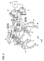
- Fig. 2 is a perspective view showing the construction of an operating mechanism of the shift forks 20 to 23.
- the shift forks 20 to 23 are fixed, respectively, to four shift rails 30 which are disposed in such a manner as to move in a back and forth direction (a shifting direction), and furthermore, shift lugs 40 are provided on the shift rails 30, respectively.
- the shift lug 40 is a sheet material which is formed into a U-shape to open upwards and is disposed in such a manner that claw portions 41 provided at an upper end portion thereof align in the back and forth direction.
- the shift lugs 40 are disposed in such a manner that center lines of their openings in the back and forth direction align with one another in such a state that they are disengaged (or in neutral positions).
- a shift shaft 50 is supported above the shift lugs 40 in such a manner as to extend over the back and forth direction center lines of the openings thereof so as to be rotated and moved in an axial direction (a selecting direction).
- Pawl-like control fingers 51 are formed on the shift shaft 50 in such a manner as to project downwards therefrom.
- the shift shaft 50 When the shift shaft 50 is slid in the axial direction so that the control finger 51 is positioned in the opening of the shift lug 40 for a target gear and the shift shaft 50 is then rotated to push the claw portion 41 of the shift lug 40 with the control finger 51, the shift forks 20 to 23 can be moved in the back and forth direction via the shift rails 30, so that the gears corresponding to the shift forks 20 to 23 can be engaged or disengaged for gearchange operations.
- the shift shaft 50 is driven to rotate by a shifting motor 60 and is driven to slide in the axial direction by a selecting motor 61 via a ball screw 63.
- the shifting motor 60 and the selecting motor 61 are controlled to be driven by an ECU 62 based on the operation of a gearshift lever, not shown, and the running conditions of the engine 8 and are controlled to be driven in such a manner that gearchanges take place sequentially, for example, when a gearchange to a target gear is implemented.
- the ECU 62 also controls the operations of the clutches 2, 3 when gearchanges take place.
- the ECU 62 controls the other clutch 3 or 2 to be engaged to engage the next gear from a state resulting before a gearchange has taken place in which one of the clutches 2 or 3 is engaged while maintaining the engagement of a gear which is engaged by the one of the clutches 2 or 3. Then, at a point in time at which the rotational speed of the gear that has just been engaged comes to synchronize with that of the previous gear, the latter gear is disengaged so as to realize a gearchange in which there is virtually no interruption of power flow as the gearchange takes place.
- Fig. 3 is a plan view showing the configuration of the shift lug 40 (40a to 40d).
- a horizontal direction denotes the selecting direction, while a vertical direction denotes the shifting direction.
- a second speed gear claw portion 41a and a sixth speed gear claw portion 41b are provided on a first shift lug 40a
- a third speed gear claw portion 41c and the first speed ear 41d are provided on a second shift lug 40b
- a reverse gear claw portion 41e and a fourth speed gear claw portion 41f are provided on a third shift lug 40c
- a fifth speed gear claw portion 41g and a parking gear claw portion are provided on a fourth shift lug 40d
- control fingers 51 formed on the shift shaft 50 four control fingers 51 (51a to 51d) are provided on the shift shaft 50 in such a manner as to be spaced apart from each other in its axial direction, and they are, from the left in the figure, a first control finger 51a, which is adapted to move the first shift lug 40a, a second control finger 51b, which is adapted to move the second shift lug 40b, a third control finger 51b, which is adapted to move the third shift lug 40c, and a fourth control finger 51d, which is adapted to move the fourth shift lug 40d.
- disengagement claw portions (second claw portions) 42 are provided on some of the shift lugs 40, and specifically speaking, a left disengagement claw portion 42a is provided on the shift lug 40b, while a right disengagement claw portion 42b is provided on the third shift lug 40c.
- the left disengagement claw portion 42a is provided in such a manner as to project rightwards as viewed in the figure from a right side of the first speed gear claw portion 41d, whereby the left disengagement claw portion 42a functions to move the second shift lug 40b downwards in the figure when the control finger 51b which is being moved downwards along the first speed gear claw portion 41d is brought into abutment therewith.
- the right disengagement claw portion 42b is provided in such a manner as to project leftwards as viewed in the figure from a left side of the reverse gear claw portion 41e, whereby the right disengagement claw portion 42b functions to move the third shift lug 40c upwards in the figure when the control finger 51c which is being moved upwards along the reverse gear claw portion 41e is brought into abutment therewith.
- the second shift lug 40b and the third shift lug 40c are constructed so as to be moved in the respective shifting directions not only when their corresponding control fingers 51b, 51c which are being positioned in the openings between the claw portions 41 thereof are moved in the shifting direction so as to push the inner surfaces of the claw portions 41b but also when the control fingers 51b, 51c pushes on the corresponding disengagement claw portions 42a, 42b.
- the left disengagement claw portion 42a is disposed such that an abutment portion S1 thereof, which constitutes a position where the second control finger 51b pushes on the left disengagement claw portion 42a, and an inner side surface S2 (a pressing portion) of the first gear claw portion 41d are offset from each other (displaced with each other) in the shifting direction, while the abutment portion S1 of the second shift lug 40b, which is in the shifting state, and an inner side surface of the other shift lug which is in the neutral state (for example, an inner side surface S3 of the sixth speed gear claw portion 41b in the figure) are placed on the same plane in the shifting direction (or are located in the same position with respect to the shifting direction).
- the right disengagement claw portion 42b has the same construction.
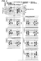
- Fig. 4 is an explanatory diagram which illustrates shifting of the control fingers 51 according to the embodiment when a gearchange takes place.
- shifting steps of the control fingers 51 are shown which take place from a state where the fourth speed gear has been engaged by disengaging the previous third speed gear to a state where the fifth speed gear is engaged.
- a vertical direction denotes the shifting direction and a horizontal direction denotes the selecting direction.
- a vertically central position denotes a neutral position.
- Each pair of claw portions 41a to 41h is made to be moved one scale vertically in the figure, and by being moved vertically outwards, a gearchange is made to the gear which corresponds to the claw portion so moved.
- the control fingers 51a to 51d are made to be moved one scale vertically from the vertical center in the figure when the shift shaft 50 is rotated.
- This stand-by state is a state in which a gearchange to the fourth speed gear has just been completed.
- the third control finger 51c has pushed an inner side of the fourth speed gear claw portion 41f so as to move it outwards, whereby the fourth speed gear is engaged.
- the third speed gear claw portion 41c is also moved outwards.
- the gearchange from the completion of engagement of the fourth speed gear to the completion of engagement of the fifth speed gear is completed through seven steps.
- Fig. 5 is an explanatory diagram which illustrates shifting of the control fingers 51 when a gearchange takes place in a first comparison example, and shifting steps of the control fingers 51 are shown from completion of a gearchange to the fourth speed gear by disengaging the previous third speed gear to completion of a gearchange to the fifth speed gear.
- control fingers 51 two control fingers, that is, a right-hand control finger 51e and a left-hand control finger 51f, are provided, and the right-hand control finger 51e is adapted to move a third shift lug 40c and a fourth shift lug 40d, while the left-hand control finger 51f is adapted to move a first shift lug 40a and a second shift lug 40b.
- Fig. 6 is an explanatory diagram which illustrates shifting of the control fingers 51 when a gearchange takes place in the second comparison example, and shifting steps of the control fingers 51 are shown from completion of a gearchange to the fourth speed gear by disengaging the previous third speed gear to completion of a gearchange to the fifth speed gear.
- the former differs from the latter in that the disengagement claw portions 42a, 42b are not provided.
- the former is constructed the same as the latter in that four control fingers are provided.
- the shift lugs 40 can be moved not only by positioning the control fingers in the openings of the claw portions 41 and then shifting the control fingers 51 in the shifting direction but also by causing the control fingers 51 to push on the disengagement claw portions 42 which project in the selecting direction from the claw portions 41 in the shifting direction. Consequently, a plurality of shifting paths for disengagement operations can be set, thereby making it possible to decrease the number of shifting steps of the control fingers 51 when a gearchange takes place.
- the pressing portion S2 of the first speed gear claw portion 41d and the abutment portion S1 of the left disengagement claw portion 42a are offset from each other in the shifting direction, while the abutment portions S1 of the second shift lug 41b which is in the shifting state and the pressing portion S3 of the other shift lug 40a which is in the neutral position are positioned on the same plane with respect to the shifting direction, when placing the second shift lug 40b which is in the shifting state in the neutral state, by shifting the second control finger 51b, which is in the neutral position, in such a manner as to approach in the selecting direction from the projecting side of the left disengagement claw portion 42a, the second control finger 51b can be moved to the abutment portion S1 without interference with the first speed gear claw portion 41d, and as the following step, shifting of the second control finger 51b in the shifting direction can be minimized.
- the shifting path of the control fingers 51 can be selected from the plurality of shifting paths, even though the number of control fingers 51 is increased, the shifting path still can be set so as to suppress the occurrence of unnecessary interference between the control fingers 51 and the claw portions 41. Consequently, by combining the provision of the disengagement claw portions 42 and the increase in the number of control fingers 51, the number of shifting steps of the control fingers 51 can largely reduced when a gearchange takes place.
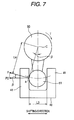
- Fig. 7 is a schematic diagram showing the construction of the shifting mechanism of the shift lug according to the embodiment.
- the control finger 51 is allowed to push the claw portion 41 while it is tilted little in the shifting direction.
- a force exerted on the claw portion 41 by a rotational torque T of the shift shaft 50 then is a tangential force F
- a distance from a contact point a between the control finger 51 and the claw portion 41 to an axial center C of the shift shaft 50 is a distance L4
- a tilt angle of a line which connects the contact point a with the axial center C of the shift shaft 50 towards the shifting direction is an angle ⁇
- a component of the tangential force F in the shifting direction that is, a component force P2 which is a force which shifts the claw portion 41 in the shifting direction is obtained by the following equation (2).
- control fingers 51 are provided more than one, even in the event that there are many gears to be changed, each control finger 51 is made to operate some of the shift lugs for gearchanges, whereby the shifting distance of each control finger in the shifting direction can be suppressed to a shorter distance. Consequently, the shifting mechanism of the control fingers 51 can be made compact in size with respect to the shifting direction.
- positions and number of disengagement claw portions 42 may be set appropriately depending upon the number and arrangement of gears.
- the invention can be applied to a transmission unit with a different number of gears from the embodiment, and the number of control fingers 51 may be set appropriately depending upon the number of gears to be provided.
- the shift lug can be moved in the shifting direction when the shift member which is being moved in the shifting direction is brought into abutment with the second claw portion to thereby push it in the shifting direction. Consequently, when shifting the shift lug, since the shift lug can be moved by the shift member being moved in the shifting direction not only in the position of the first claw portion in the selecting direction but also in the position of the second claw portion in the selecting direction, the range of selection of shifting paths of the shift member is increased, and it can be set such that the movements of the shift member are simplified during gearchanges.
- the shift forks can be operated from the neutral state to the shifting state quickly and efficiently, and this enables gearchanges in which the shift forks can be operated from the neutral state to the shifting state quickly and efficiently.
- the shift member when shifting the shift member in the selecting direction, the shift member can be placed to the second claw portion without interference with the first claw portion, and this enables gearchanges in which the shift forks can be operated from the neutral state to the shifting state quickly and efficiently.
- the shift member can be moved in the shifting direction and the selecting direction by rotating and shifting the shaft in the selecting direction by the actuator. Consequently, the shifting mechanism for shifting the shift member in the shifting direction and the selecting direction can be realized with the simple configuration.
- each shift member can be set to operate some or others of the shift rails for gearchanges, whereby the shifting of each shift member in the selecting direction can be reduced. Consequently, the shifting mechanism of the shift members can be made compact in size with respect to the selecting direction.
Landscapes
- Engineering & Computer Science (AREA)
- General Engineering & Computer Science (AREA)
- Mechanical Engineering (AREA)
- Gear-Shifting Mechanisms (AREA)
Applications Claiming Priority (1)
| Application Number | Priority Date | Filing Date | Title |
|---|---|---|---|
| JP2007207917A JP4235847B2 (ja) | 2007-08-09 | 2007-08-09 | 変速装置 |
Publications (3)
| Publication Number | Publication Date |
|---|---|
| EP2028396A2 true EP2028396A2 (fr) | 2009-02-25 |
| EP2028396A3 EP2028396A3 (fr) | 2009-12-02 |
| EP2028396B1 EP2028396B1 (fr) | 2013-08-28 |
Family
ID=40001458
Family Applications (1)
| Application Number | Title | Priority Date | Filing Date |
|---|---|---|---|
| EP08153155.0A Expired - Fee Related EP2028396B1 (fr) | 2007-08-09 | 2008-03-20 | Transmission |
Country Status (6)
| Country | Link |
|---|---|
| US (1) | US7628089B2 (fr) |
| EP (1) | EP2028396B1 (fr) |
| JP (1) | JP4235847B2 (fr) |
| KR (1) | KR100897464B1 (fr) |
| CN (1) | CN101363537B (fr) |
| RU (1) | RU2374533C1 (fr) |
Cited By (4)
| Publication number | Priority date | Publication date | Assignee | Title |
|---|---|---|---|---|
| EP2000707A3 (fr) * | 2007-06-07 | 2009-11-25 | Mitsubishi Jidosha Kogyo Kabushiki Kaisha | Transmission |
| EP2003374A3 (fr) * | 2007-06-11 | 2009-12-16 | Mitsubishi Jidosha Kogyo Kabushiki Kaisha | Transmission |
| EP2196707A3 (fr) * | 2008-12-11 | 2010-12-15 | Hyundai Mobis Co., Ltd. | Dispositif de changement de vitesses de transmission à embrayage double |
| EP2443368A4 (fr) * | 2009-06-17 | 2012-11-21 | Scania Cv Ab | Dispositif d'actionnement automatique d'une boîte de vitesses manuelle |
Families Citing this family (11)
| Publication number | Priority date | Publication date | Assignee | Title |
|---|---|---|---|---|
| JP2008045663A (ja) * | 2006-08-16 | 2008-02-28 | Mitsubishi Fuso Truck & Bus Corp | 変速装置 |
| US7861613B2 (en) * | 2007-04-17 | 2011-01-04 | Eaton Corporation | Selector mechanism for dual-clutch transmissions |
| JP4333800B2 (ja) * | 2008-02-14 | 2009-09-16 | 三菱自動車工業株式会社 | 自動変速機の変速操作装置 |
| JP4285580B1 (ja) * | 2008-02-22 | 2009-06-24 | 三菱自動車工業株式会社 | 自動変速機の変速操作装置 |
| KR101028306B1 (ko) | 2009-07-15 | 2011-04-11 | 현대자동차주식회사 | 듀얼클러치 변속기의 변속장치 |
| JP5815988B2 (ja) * | 2011-05-25 | 2015-11-17 | アイシン・エーアイ株式会社 | 手動変速機 |
| JP5895702B2 (ja) * | 2012-05-18 | 2016-03-30 | いすゞ自動車株式会社 | 車両の変速装置 |
| CN103486248B (zh) * | 2013-09-13 | 2017-09-22 | 浙江吉利控股集团有限公司 | 一种选换挡执行机构 |
| CN112228547B (zh) * | 2019-06-30 | 2022-06-14 | 比亚迪股份有限公司 | 一种换挡机构、换挡控制方法、计算机存储介质及车辆 |
| CN114364557A (zh) * | 2019-09-30 | 2022-04-15 | 株式会社爱信 | 车用驱动传递装置 |
| KR20210100234A (ko) * | 2020-02-05 | 2021-08-17 | 현대자동차주식회사 | 변속기용 액츄에이터 |
Citations (2)
| Publication number | Priority date | Publication date | Assignee | Title |
|---|---|---|---|---|
| EP0300843A1 (fr) | 1987-07-20 | 1989-01-25 | Automobiles Peugeot | Dispositif de freinage de pignons d'une boîte de vitesses de véhicule automobile |
| EP0599206A1 (fr) | 1992-11-27 | 1994-06-01 | Mitsubishi Jidosha Kogyo Kabushiki Kaisha | Dispositif d'actionnement de boîte de vitesse |
Family Cites Families (19)
| Publication number | Priority date | Publication date | Assignee | Title |
|---|---|---|---|---|
| US3866488A (en) * | 1972-01-24 | 1975-02-18 | Toyota Motor Co Ltd | Manually operated shift assembly with restraining action for shifting to reverse |
| SU889494A1 (ru) * | 1979-02-01 | 1981-12-15 | За витель | Механизм переключени коробки передач транспортного средства |
| IT1161521B (it) * | 1983-10-21 | 1987-03-18 | Iveco Fiat | Dispositivo per la selezione ed il comando delle marce di un cambio di velocita di veicoli in particolare di veicoli industriali |
| FR2615798B1 (fr) * | 1987-05-25 | 1989-09-15 | Peugeot | Dispositif de commande d'une boite de vitesses de vehicule automobile |
| FR2651849B1 (fr) * | 1989-09-08 | 1995-06-30 | Peugeot | Dispositif de commande d'une boite de vitesses de vehicule automobile. |
| US5408898A (en) * | 1993-11-10 | 1995-04-25 | Eaton Corporation | Preselect shift strategy using stored energy |
| EP0708277A1 (fr) * | 1994-10-18 | 1996-04-24 | Société Anonyme dite: REGIE NATIONALE DES USINES RENAULT | Dispositif et procédé de commande de boîte de vitesses |
| JP3842518B2 (ja) | 2000-04-24 | 2006-11-08 | 愛知機械工業株式会社 | 自動変速機の変速装置 |
| FR2831634B1 (fr) * | 2001-10-31 | 2004-02-27 | Renault | Boite de vitesses a selection masquee |
| DE10231547A1 (de) | 2002-07-11 | 2004-01-22 | Zf Friedrichshafen Ag | Schaltvorrichtung |
| DE10253471A1 (de) | 2002-11-16 | 2004-08-26 | Zf Friedrichshafen Ag | Schaltvorrichtung für ein Getriebe |
| FR2859006B1 (fr) * | 2003-08-21 | 2005-11-18 | Peugeot Citroen Automobiles Sa | Dispositif de changement de vitesse, ensemble et vehicule automobile correpondants |
| JP4409896B2 (ja) * | 2003-09-19 | 2010-02-03 | 本田技研工業株式会社 | マニュアルトランスミッションの変速操作機構 |
| DE102004006682A1 (de) * | 2004-02-11 | 2005-09-15 | Zf Friedrichshafen Ag | Einstangenschaltvorrichtung an einem Schaltgetriebe |
| JP4560337B2 (ja) * | 2004-06-15 | 2010-10-13 | アイシン・エーアイ株式会社 | 歯車変速装置 |
| KR100793875B1 (ko) * | 2006-05-30 | 2008-01-15 | 현대자동차주식회사 | 수동 변속기 및 수동 변속기의 시프트 러그 구조 |
| JP4696221B2 (ja) * | 2007-03-01 | 2011-06-08 | 三菱自動車工業株式会社 | 同期噛み合い式自動変速装置 |
| JP4235844B2 (ja) * | 2007-06-07 | 2009-03-11 | 三菱自動車工業株式会社 | 変速装置 |
| JP4235845B2 (ja) * | 2007-06-11 | 2009-03-11 | 三菱自動車工業株式会社 | 変速装置 |
-
2007
- 2007-08-09 JP JP2007207917A patent/JP4235847B2/ja not_active Expired - Fee Related
-
2008
- 2008-02-18 KR KR1020080014372A patent/KR100897464B1/ko not_active Expired - Fee Related
- 2008-03-19 US US12/051,243 patent/US7628089B2/en not_active Expired - Fee Related
- 2008-03-20 CN CN2008100871755A patent/CN101363537B/zh not_active Expired - Fee Related
- 2008-03-20 RU RU2008110833/11A patent/RU2374533C1/ru not_active IP Right Cessation
- 2008-03-20 EP EP08153155.0A patent/EP2028396B1/fr not_active Expired - Fee Related
Patent Citations (2)
| Publication number | Priority date | Publication date | Assignee | Title |
|---|---|---|---|---|
| EP0300843A1 (fr) | 1987-07-20 | 1989-01-25 | Automobiles Peugeot | Dispositif de freinage de pignons d'une boîte de vitesses de véhicule automobile |
| EP0599206A1 (fr) | 1992-11-27 | 1994-06-01 | Mitsubishi Jidosha Kogyo Kabushiki Kaisha | Dispositif d'actionnement de boîte de vitesse |
Cited By (6)
| Publication number | Priority date | Publication date | Assignee | Title |
|---|---|---|---|---|
| EP2000707A3 (fr) * | 2007-06-07 | 2009-11-25 | Mitsubishi Jidosha Kogyo Kabushiki Kaisha | Transmission |
| EP2003374A3 (fr) * | 2007-06-11 | 2009-12-16 | Mitsubishi Jidosha Kogyo Kabushiki Kaisha | Transmission |
| EP2196707A3 (fr) * | 2008-12-11 | 2010-12-15 | Hyundai Mobis Co., Ltd. | Dispositif de changement de vitesses de transmission à embrayage double |
| EP2443368A4 (fr) * | 2009-06-17 | 2012-11-21 | Scania Cv Ab | Dispositif d'actionnement automatique d'une boîte de vitesses manuelle |
| RU2496040C2 (ru) * | 2009-06-17 | 2013-10-20 | Сканиа Св Аб | Управляющее устройство для полуавтоматической коробки передач (варианты), коробка передач (варианты) и транспортное средство (варианты) |
| US9127767B2 (en) | 2009-06-17 | 2015-09-08 | Scania Cv Ab | Device for the automatic operation of a manual gear box |
Also Published As
| Publication number | Publication date |
|---|---|
| KR100897464B1 (ko) | 2009-05-14 |
| JP2009041677A (ja) | 2009-02-26 |
| JP4235847B2 (ja) | 2009-03-11 |
| US20090038423A1 (en) | 2009-02-12 |
| CN101363537A (zh) | 2009-02-11 |
| US7628089B2 (en) | 2009-12-08 |
| RU2374533C1 (ru) | 2009-11-27 |
| CN101363537B (zh) | 2012-11-28 |
| EP2028396B1 (fr) | 2013-08-28 |
| KR20090015782A (ko) | 2009-02-12 |
| RU2008110833A (ru) | 2009-09-27 |
| EP2028396A3 (fr) | 2009-12-02 |
Similar Documents
| Publication | Publication Date | Title |
|---|---|---|
| EP2028396B1 (fr) | Transmission | |
| EP2003374A2 (fr) | Transmission | |
| JP4399197B2 (ja) | 手動変速機のシフトチェンジ装置 | |
| EP2000707B1 (fr) | Transmission | |
| US7694605B2 (en) | Gear change control system of automatic transmission | |
| US20090211389A1 (en) | Gear change control system of automatic transmission | |
| CN101749422A (zh) | 用于双离合器变速器的换档装置 | |
| JP4179479B2 (ja) | 変速機のシフトチェンジ装置 | |
| EP2110578A2 (fr) | Appareil de transmission automatique à embrayage double | |
| US5966990A (en) | Shifting arrangement for, and method of shifting, a manual transmission | |
| JP4333272B2 (ja) | 変速機の変速操作機構及びその設計方法 | |
| JP3170257B2 (ja) | 変速機のギヤシフト機構 | |
| CN107429839B (zh) | 拨叉模块 | |
| JP6459173B2 (ja) | 副変速機構付き変速機 | |
| JP2012255505A (ja) | 歯車構造 |
Legal Events
| Date | Code | Title | Description |
|---|---|---|---|
| PUAI | Public reference made under article 153(3) epc to a published international application that has entered the european phase |
Free format text: ORIGINAL CODE: 0009012 |
|
| 17P | Request for examination filed |
Effective date: 20080320 |
|
| AK | Designated contracting states |
Kind code of ref document: A2 Designated state(s): AT BE BG CH CY CZ DE DK EE ES FI FR GB GR HR HU IE IS IT LI LT LU LV MC MT NL NO PL PT RO SE SI SK TR |
|
| AX | Request for extension of the european patent |
Extension state: AL BA MK RS |
|
| PUAL | Search report despatched |
Free format text: ORIGINAL CODE: 0009013 |
|
| AK | Designated contracting states |
Kind code of ref document: A3 Designated state(s): AT BE BG CH CY CZ DE DK EE ES FI FR GB GR HR HU IE IS IT LI LT LU LV MC MT NL NO PL PT RO SE SI SK TR |
|
| AX | Request for extension of the european patent |
Extension state: AL BA MK RS |
|
| AKX | Designation fees paid |
Designated state(s): DE FR GB |
|
| 17Q | First examination report despatched |
Effective date: 20110523 |
|
| REG | Reference to a national code |
Ref country code: DE Ref legal event code: R079 Ref document number: 602008027130 Country of ref document: DE Free format text: PREVIOUS MAIN CLASS: F16H0063300000 Ipc: F16H0063220000 |
|
| RIC1 | Information provided on ipc code assigned before grant |
Ipc: F16H 63/22 20060101AFI20120803BHEP Ipc: F16H 63/26 20060101ALI20120803BHEP Ipc: F16H 61/688 20060101ALI20120803BHEP |
|
| GRAC | Information related to communication of intention to grant a patent modified |
Free format text: ORIGINAL CODE: EPIDOSCIGR1 |
|
| GRAP | Despatch of communication of intention to grant a patent |
Free format text: ORIGINAL CODE: EPIDOSNIGR1 |
|
| GRAS | Grant fee paid |
Free format text: ORIGINAL CODE: EPIDOSNIGR3 |
|
| GRAP | Despatch of communication of intention to grant a patent |
Free format text: ORIGINAL CODE: EPIDOSNIGR1 |
|
| GRAA | (expected) grant |
Free format text: ORIGINAL CODE: 0009210 |
|
| AK | Designated contracting states |
Kind code of ref document: B1 Designated state(s): DE FR GB |
|
| REG | Reference to a national code |
Ref country code: GB Ref legal event code: FG4D |
|
| REG | Reference to a national code |
Ref country code: DE Ref legal event code: R096 Ref document number: 602008027130 Country of ref document: DE Effective date: 20131024 |
|
| PGFP | Annual fee paid to national office [announced via postgrant information from national office to epo] |
Ref country code: DE Payment date: 20140331 Year of fee payment: 7 |
|
| PGFP | Annual fee paid to national office [announced via postgrant information from national office to epo] |
Ref country code: FR Payment date: 20140212 Year of fee payment: 7 |
|
| REG | Reference to a national code |
Ref country code: DE Ref legal event code: R097 Ref document number: 602008027130 Country of ref document: DE |
|
| PGFP | Annual fee paid to national office [announced via postgrant information from national office to epo] |
Ref country code: GB Payment date: 20140319 Year of fee payment: 7 |
|
| PLBE | No opposition filed within time limit |
Free format text: ORIGINAL CODE: 0009261 |
|
| STAA | Information on the status of an ep patent application or granted ep patent |
Free format text: STATUS: NO OPPOSITION FILED WITHIN TIME LIMIT |
|
| 26N | No opposition filed |
Effective date: 20140530 |
|
| REG | Reference to a national code |
Ref country code: DE Ref legal event code: R097 Ref document number: 602008027130 Country of ref document: DE Effective date: 20140530 |
|
| REG | Reference to a national code |
Ref country code: DE Ref legal event code: R119 Ref document number: 602008027130 Country of ref document: DE |
|
| GBPC | Gb: european patent ceased through non-payment of renewal fee |
Effective date: 20150320 |
|
| REG | Reference to a national code |
Ref country code: FR Ref legal event code: ST Effective date: 20151130 |
|
| PG25 | Lapsed in a contracting state [announced via postgrant information from national office to epo] |
Ref country code: DE Free format text: LAPSE BECAUSE OF NON-PAYMENT OF DUE FEES Effective date: 20151001 Ref country code: GB Free format text: LAPSE BECAUSE OF NON-PAYMENT OF DUE FEES Effective date: 20150320 |
|
| PG25 | Lapsed in a contracting state [announced via postgrant information from national office to epo] |
Ref country code: FR Free format text: LAPSE BECAUSE OF NON-PAYMENT OF DUE FEES Effective date: 20150331 |