EP2028505A2 - Kühleinheit einer DNP-Vorrichtung - Google Patents
Kühleinheit einer DNP-Vorrichtung Download PDFInfo
- Publication number
- EP2028505A2 EP2028505A2 EP08161758A EP08161758A EP2028505A2 EP 2028505 A2 EP2028505 A2 EP 2028505A2 EP 08161758 A EP08161758 A EP 08161758A EP 08161758 A EP08161758 A EP 08161758A EP 2028505 A2 EP2028505 A2 EP 2028505A2
- Authority
- EP
- European Patent Office
- Prior art keywords
- coolant
- inner bore
- bore tube
- dnp
- working region
- Prior art date
- Legal status (The legal status is an assumption and is not a legal conclusion. Google has not performed a legal analysis and makes no representation as to the accuracy of the status listed.)
- Withdrawn
Links
- 239000002826 coolant Substances 0.000 title claims abstract description 68
- 239000002699 waste material Substances 0.000 claims abstract description 16
- 238000000034 method Methods 0.000 claims abstract description 6
- 238000005086 pumping Methods 0.000 claims abstract description 3
- 230000005855 radiation Effects 0.000 claims description 13
- 239000001307 helium Substances 0.000 claims description 11
- 229910052734 helium Inorganic materials 0.000 claims description 11
- SWQJXJOGLNCZEY-UHFFFAOYSA-N helium atom Chemical compound [He] SWQJXJOGLNCZEY-UHFFFAOYSA-N 0.000 claims description 11
- 239000007788 liquid Substances 0.000 claims description 11
- 239000002904 solvent Substances 0.000 claims description 4
- 238000002844 melting Methods 0.000 claims 1
- 230000008018 melting Effects 0.000 claims 1
- 238000005481 NMR spectroscopy Methods 0.000 description 17
- 238000001816 cooling Methods 0.000 description 4
- 238000003780 insertion Methods 0.000 description 3
- 230000037431 insertion Effects 0.000 description 3
- 239000000463 material Substances 0.000 description 3
- IJGRMHOSHXDMSA-UHFFFAOYSA-N Atomic nitrogen Chemical compound N#N IJGRMHOSHXDMSA-UHFFFAOYSA-N 0.000 description 2
- 229920002799 BoPET Polymers 0.000 description 2
- OKTJSMMVPCPJKN-UHFFFAOYSA-N Carbon Chemical compound [C] OKTJSMMVPCPJKN-UHFFFAOYSA-N 0.000 description 2
- 239000005041 Mylar™ Substances 0.000 description 2
- 229910052799 carbon Inorganic materials 0.000 description 2
- 238000004458 analytical method Methods 0.000 description 1
- 238000000429 assembly Methods 0.000 description 1
- 238000004090 dissolution Methods 0.000 description 1
- 238000007689 inspection Methods 0.000 description 1
- 238000002595 magnetic resonance imaging Methods 0.000 description 1
- 229910052757 nitrogen Inorganic materials 0.000 description 1
- 230000000717 retained effect Effects 0.000 description 1
- 230000035945 sensitivity Effects 0.000 description 1
- 239000007921 spray Substances 0.000 description 1
Images


Classifications
-
- G—PHYSICS
- G01—MEASURING; TESTING
- G01R—MEASURING ELECTRIC VARIABLES; MEASURING MAGNETIC VARIABLES
- G01R33/00—Arrangements or instruments for measuring magnetic variables
- G01R33/20—Arrangements or instruments for measuring magnetic variables involving magnetic resonance
- G01R33/28—Details of apparatus provided for in groups G01R33/44 - G01R33/64
- G01R33/30—Sample handling arrangements, e.g. sample cells, spinning mechanisms
- G01R33/31—Temperature control thereof
-
- G—PHYSICS
- G01—MEASURING; TESTING
- G01R—MEASURING ELECTRIC VARIABLES; MEASURING MAGNETIC VARIABLES
- G01R33/00—Arrangements or instruments for measuring magnetic variables
- G01R33/20—Arrangements or instruments for measuring magnetic variables involving magnetic resonance
- G01R33/28—Details of apparatus provided for in groups G01R33/44 - G01R33/64
- G01R33/282—Means specially adapted for hyperpolarisation or for hyperpolarised contrast agents, e.g. for the generation of hyperpolarised gases using optical pumping cells, for storing hyperpolarised contrast agents or for the determination of the polarisation of a hyperpolarised contrast agent
-
- G—PHYSICS
- G01—MEASURING; TESTING
- G01R—MEASURING ELECTRIC VARIABLES; MEASURING MAGNETIC VARIABLES
- G01R33/00—Arrangements or instruments for measuring magnetic variables
- G01R33/20—Arrangements or instruments for measuring magnetic variables involving magnetic resonance
- G01R33/62—Arrangements or instruments for measuring magnetic variables involving magnetic resonance using double resonance
-
- G—PHYSICS
- G01—MEASURING; TESTING
- G01R—MEASURING ELECTRIC VARIABLES; MEASURING MAGNETIC VARIABLES
- G01R33/00—Arrangements or instruments for measuring magnetic variables
- G01R33/20—Arrangements or instruments for measuring magnetic variables involving magnetic resonance
- G01R33/44—Arrangements or instruments for measuring magnetic variables involving magnetic resonance using nuclear magnetic resonance [NMR]
- G01R33/445—MR involving a non-standard magnetic field B0, e.g. of low magnitude as in the earth's magnetic field or in nanoTesla spectroscopy, comprising a polarizing magnetic field for pre-polarisation, B0 with a temporal variation of its magnitude or direction such as field cycling of B0 or rotation of the direction of B0, or spatially inhomogeneous B0 like in fringe-field MR or in stray-field imaging
-
- G—PHYSICS
- G01—MEASURING; TESTING
- G01R—MEASURING ELECTRIC VARIABLES; MEASURING MAGNETIC VARIABLES
- G01R33/00—Arrangements or instruments for measuring magnetic variables
- G01R33/20—Arrangements or instruments for measuring magnetic variables involving magnetic resonance
- G01R33/44—Arrangements or instruments for measuring magnetic variables involving magnetic resonance using nuclear magnetic resonance [NMR]
- G01R33/48—NMR imaging systems
- G01R33/4808—Multimodal MR, e.g. MR combined with positron emission tomography [PET], MR combined with ultrasound or MR combined with computed tomography [CT]
Definitions
- the invention relates to DNP (dynamic nuclear polarisation) apparatus.
- DNP dynamic nuclear polarisation
- a coolant sub-assembly for use in a DNP apparatus comprises:
- the coolant waste path opens into said first end of the inner bore tube while in other examples, it opens into said second end of the inner bore tube. In a third example, the coolant waste path can open into both ends of the inner bore tube.
- the auxiliary coolant supply path is defined by one or more capillaries extending from the coolant supply path to corresponding ones of said aperture(s) in the inner bore tube wall.
- This structure enables the coolant flow to be accurately determined and further control can be achieved by providing a heater coupled to one or more of the capillaries.
- the sub-assembly preferably further comprises one or more resilient baffles extending across the inner bore tube, between the first and the second end of the inner bore tube apertures, for reducing heat radiation and being sufficiently flexible to allow movement of a sample holder past the or each baffle.
- the baffles should be made of a suitable reflective material such as mylar.
- the arrangement of concentric jackets can be chosen depending upon each application.
- the arrangement will include at least one radiation shield and an evacuated region and/or coolant containing region. The choice will depend upon the temperature at which the inner bore tube is to be maintained as well as whether a suitable coolant is available etc.
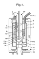
- the coolant sub-assembly (or cryo-insert) shown in Figure 1 comprises an inner bore tube 6 surrounded by a number of concentric jackets including inner and outer radiation shields 14, 7, an outer vacuum chamber wall 16 and an outer sock 17. In some cases, only one radiation shield may be needed.
- the inner bore tube 6 is vertically oriented and has an upper, first opening closed by a seal 19 through which a sample insertion rod 9 can be removably inserted.
- the rod 9 has a sample holder 18 removably mounted at its lower end, the sample holder being shown in Figure 1 located at a DNP working region indicated by a shaded area 21.
- the spaces between the inner bore tube 6 and the radiation shield 7, and between the radiation shields 7 and 16 are evacuated.
- a primary liquid helium coolant supply path is used to provide primary cooling to the inner bore tube 6.
- This supply path comprises a capillary 2 connected at its upper end to a storage dewar 40 ( Figure 2 ) via a syphon 1, the capillary 2 extending through the evacuated space defined between the inner bore tube 6 and radiation shield 7 to a heat exchanger 4.
- expansion and cooling occur at about 3-4K.
- the gaseous helium then flows back through a tube section 5 thermally coupled to a radiation shield 7 so as to cool this outer radiation shield and finally back to a syphon jacket 8 surrounding the capillary 2 where it cools the incoming helium in the capillary 2.
- the main flow of liquid helium through this coolant path is promoted by a small vacuum pump 42 at the supply dewar.
- the sample insertion rod 9 is cooled via conduction through the bore and hence to the main liquid helium flow path using spring fingers 10 which also guide and centralise the rod within the inner bore tube 6.
- an auxiliary coolant flow path is provided in which a small proportion of the liquid helium from the heat exchanger 4 is diverted to flow via one or more long capillaries 11 a, 11 b and, having undergone a pseudo-isenthalpic expansion, is bled into the main bore of the inner bore tube 6 via corresponding first apertures 12A,12B to spray onto the sample and form a supercooled film.
- the impedance of the two capillaries can be varied by applying current to one or more small heaters 13 wrapped around the capillaries.
- the heater 13 is shown wrapped around the capillary 11 a in Figure 1 but it could be provided around the capillary 11 b or indeed both capillaries 11 a, 11 b could have respective heaters.
- the main bore is evacuated through a first coolant waste path 60 via a high capacity vacuum pump 44.
- This high capacity vacuum pump 44 is connected to an opening 26 at the upper end of the inner bore tube 6.
- a further coolant waste path 62 is provided exiting through the second, lower end 22 of the inner bore tube 6 and passing up between the outer vacuum chamber wall 16 and the outer sock 17 into the upper end of the inner bore tube 6 and then out through the opening 26.
- the temperature at the lower end of the inner bore tube will be substantially room temperature. It is therefore important to control to a minimum radiation (and convection) of heat in the lower half of the inner bore tube 6 and this is achieved in this example by the insertion of several reflective aluminised mylar film baffles 15. These also block direct radiation from the lower end of the bore.
- the baffles are slit (not shown) with cross-cuts which are adapted not to impede vapour flow and also allow the rod 9 to pass easily therethrough when the sample is moved down towards the NMR apparatus.
- liquid Helium is used as the coolant in this example, other coolants such as liquid nitrogen could also be used, particularly for cooling the cryostat jackets.
- FIG 3 illustrates schematically the cryo-insert 30 of Figure 1 located in a room temperature bore 32 of a cryostat 34.
- DNP and NMR magnets 36,37 are located coaxially in the cryostat 34 so that they can be operated under superconducting conditions to generate high field strengths in the DNP working region 21 and an NMR working region 38 respectively.
- Figure 3 also illustrates the microwave cavity 40 at the DNP region 21 and microwave feed 42.
- a sample is placed in the sample holder 18 which is then mounted on the end of the sample holding rod 9 and the rod 9 is inserted into the inner bore tube 6 through the seal 19.
- the sample holder 18 is then brought into the DNP working region 21.
- the flow of liquid helium through the auxiliary coolant path causes liquid to begin to flow over the sample and cool it to very low temperature.
- the sample which is located in the cavity 40, is irradiated with microwaves to achieve hyper polarisation.
- the sample holding rod 9 is then pushed further down through the bore tube 6 so that the sample holder passes through the film baffles 15 to a dissolution position 20. At this position, solvent is supplied to the sample holder, either through the sample holding rod 9 or by some other means, to dissolve the sample. In other examples, the hyper polarised sample is melted, for example by means of a heater or laser or other known method. Once the sample has been dissolved (or melted), the sample holding rod 9 is pushed further down to transfer the sample into the NMR working region 38 where the NMR process can be carried out.
- all waste helium passes up through the inner bore tube 6 and out to the vacuum pump through opening 26.
- all waste liquid helium is extracted through the lower end 22 of the inner bore tube 6 using a vacuum pump.
Landscapes
- Physics & Mathematics (AREA)
- Condensed Matter Physics & Semiconductors (AREA)
- General Physics & Mathematics (AREA)
- Sampling And Sample Adjustment (AREA)
Priority Applications (1)
| Application Number | Priority Date | Filing Date | Title |
|---|---|---|---|
| EP08161758A EP2028505A3 (de) | 2007-08-24 | 2008-08-04 | Kühleinheit einer DNP-Vorrichtung |
Applications Claiming Priority (2)
| Application Number | Priority Date | Filing Date | Title |
|---|---|---|---|
| EP07114986 | 2007-08-24 | ||
| EP08161758A EP2028505A3 (de) | 2007-08-24 | 2008-08-04 | Kühleinheit einer DNP-Vorrichtung |
Publications (2)
| Publication Number | Publication Date |
|---|---|
| EP2028505A2 true EP2028505A2 (de) | 2009-02-25 |
| EP2028505A3 EP2028505A3 (de) | 2010-03-17 |
Family
ID=38896947
Family Applications (1)
| Application Number | Title | Priority Date | Filing Date |
|---|---|---|---|
| EP08161758A Withdrawn EP2028505A3 (de) | 2007-08-24 | 2008-08-04 | Kühleinheit einer DNP-Vorrichtung |
Country Status (3)
| Country | Link |
|---|---|
| US (1) | US7646200B2 (de) |
| EP (1) | EP2028505A3 (de) |
| JP (1) | JP2009053199A (de) |
Cited By (3)
| Publication number | Priority date | Publication date | Assignee | Title |
|---|---|---|---|---|
| WO2010020776A3 (en) * | 2008-08-19 | 2010-06-03 | Oxford Instruments Molecular Biotools Limited | Dynamic nuclear polarisation system |
| US9279868B2 (en) | 2011-12-29 | 2016-03-08 | Bruker Biospin Gmbh | Device and method for rapid dynamic nuclear polarization |
| EP3540452A1 (de) * | 2018-03-07 | 2019-09-18 | General Electric Company | Thermischer zwischenträger für ein kryogenes kühlsystem |
Families Citing this family (9)
| Publication number | Priority date | Publication date | Assignee | Title |
|---|---|---|---|---|
| DE102008033886B4 (de) * | 2008-07-18 | 2012-03-08 | Bruker Biospin Ag | Apparatur zur Durchführung von DNP-NMR Messungen mit Kompensationsanordnung |
| EP2343568A1 (de) | 2009-12-30 | 2011-07-13 | Koninklijke Philips Electronics N.V. | Dynamische Kernpolarisationsvorrichtung mit Proben-Fördereinrichtung |
| US8786284B2 (en) | 2011-01-11 | 2014-07-22 | Bridge12 Technologies, Inc. | Integrated high-frequency generator system utilizing the magnetic field of the target application |
| EP2795355B1 (de) | 2011-12-23 | 2019-04-03 | Stichting Katholieke Universiteit | Kernmagnetresonanzvorrichtung mit schneller zyklischer dynamischer nuklearer polarisierung |
| US9329246B2 (en) | 2012-10-03 | 2016-05-03 | Bruker Biospin Ag | Method for hyperpolarization transfer in the liquid state |
| CN105474027A (zh) | 2013-05-03 | 2016-04-06 | 量子谷投资基金有限合伙公司 | 转移自旋极化 |
| CA2910540C (en) | 2013-05-03 | 2020-03-10 | Quantum Valley Investment Fund LP | Using a cavity to polarize a spin ensemble |
| DE102013219453B8 (de) * | 2013-09-26 | 2014-10-02 | Bruker Biospin Ag | DNP-Vorrichtung |
| US9587215B2 (en) | 2014-08-07 | 2017-03-07 | General Electric Company | Devices, systems and methods for automated transfer of a sample |
Citations (2)
| Publication number | Priority date | Publication date | Assignee | Title |
|---|---|---|---|---|
| WO2002037132A1 (en) | 2000-11-03 | 2002-05-10 | Amersham Health As | Methods and devices for dissolving hyperpolarised solid material for nmr analyses |
| WO2005114244A1 (en) | 2004-05-18 | 2005-12-01 | Oxford Instruments Superconductivity Limited | Apparatus and method for performing in-vitro dnp-nmr measurements |
Family Cites Families (12)
| Publication number | Priority date | Publication date | Assignee | Title |
|---|---|---|---|---|
| FI105447B (fi) * | 1998-11-03 | 2000-08-31 | Raimo Pentti Juhani Joensuu | Järjestely kohteen tutkimiseen |
| US6396274B1 (en) * | 1999-11-05 | 2002-05-28 | Varian, Inc. | Dual-function NMR probe |
| GB0014715D0 (en) * | 2000-06-15 | 2000-08-09 | Cryogenic Ltd | Method and apparatus for providing a variable temperature sample space |
| US6672076B2 (en) * | 2001-02-09 | 2004-01-06 | Bsst Llc | Efficiency thermoelectrics utilizing convective heat flow |
| US6515260B1 (en) * | 2001-11-07 | 2003-02-04 | Varian, Inc. | Method and apparatus for rapid heating of NMR samples |
| GB0424725D0 (en) * | 2004-11-09 | 2004-12-08 | Oxford Instr Superconductivity | Cryostat assembly |
| GB0501346D0 (en) * | 2005-01-21 | 2005-03-02 | Oxford Instr Molecular Biotool | Method of carrying out dynamic nuclear polarization |
| GB0507174D0 (en) * | 2005-04-08 | 2005-05-18 | Oxford Instr Molecular Biotool | Method of operating a dynamic nuclear polarization system |
| GB0514303D0 (en) * | 2005-07-12 | 2005-08-17 | Oxford Instr Molecular Biotool | Magnet assembly |
| JP2007021008A (ja) * | 2005-07-20 | 2007-02-01 | Hitachi Ltd | Dnp過分極手段を備えた磁気共鳴イメージング装置 |
| US7631507B2 (en) * | 2006-11-02 | 2009-12-15 | General Electric Company | Methods and devices for polarized samples for use in MRI |
| US20080240998A1 (en) * | 2007-03-28 | 2008-10-02 | Urbahn John A | Fluid path system for dissolution and transport of a hyperpolarized material |
-
2008
- 2008-08-04 EP EP08161758A patent/EP2028505A3/de not_active Withdrawn
- 2008-08-19 US US12/194,283 patent/US7646200B2/en not_active Expired - Fee Related
- 2008-08-22 JP JP2008241680A patent/JP2009053199A/ja active Pending
Patent Citations (2)
| Publication number | Priority date | Publication date | Assignee | Title |
|---|---|---|---|---|
| WO2002037132A1 (en) | 2000-11-03 | 2002-05-10 | Amersham Health As | Methods and devices for dissolving hyperpolarised solid material for nmr analyses |
| WO2005114244A1 (en) | 2004-05-18 | 2005-12-01 | Oxford Instruments Superconductivity Limited | Apparatus and method for performing in-vitro dnp-nmr measurements |
Cited By (3)
| Publication number | Priority date | Publication date | Assignee | Title |
|---|---|---|---|---|
| WO2010020776A3 (en) * | 2008-08-19 | 2010-06-03 | Oxford Instruments Molecular Biotools Limited | Dynamic nuclear polarisation system |
| US9279868B2 (en) | 2011-12-29 | 2016-03-08 | Bruker Biospin Gmbh | Device and method for rapid dynamic nuclear polarization |
| EP3540452A1 (de) * | 2018-03-07 | 2019-09-18 | General Electric Company | Thermischer zwischenträger für ein kryogenes kühlsystem |
Also Published As
| Publication number | Publication date |
|---|---|
| JP2009053199A (ja) | 2009-03-12 |
| US20090051361A1 (en) | 2009-02-26 |
| EP2028505A3 (de) | 2010-03-17 |
| US7646200B2 (en) | 2010-01-12 |
Similar Documents
| Publication | Publication Date | Title |
|---|---|---|
| EP2028505A2 (de) | Kühleinheit einer DNP-Vorrichtung | |
| Comment et al. | Design and performance of a DNP prepolarizer coupled to a rodent MRI scanner | |
| Kouřil et al. | Scalable dissolution-dynamic nuclear polarization with rapid transfer of a polarized solid | |
| JP4340318B2 (ja) | インビトロdnp−nmr測定を行うための装置及び方法 | |
| EP1902327B1 (de) | Magnetbaugruppe für dnp- und/oder nmr-anwendungen | |
| US20010013779A1 (en) | Cooled NMR probe head with thermal insulation of the sample | |
| Cheng et al. | A multisample 7 T dynamic nuclear polarization polarizer for preclinical hyperpolarized MR | |
| EP1866659B1 (de) | Verfahren für den betrieb eines dynamischen kernpolarisationssystems | |
| Sharma et al. | Rapid-melt dynamic nuclear polarization | |
| EP1746431A1 (de) | Gerät der bildgebenden magnetischen Resonanz mit Mitteln zur Hyperpolarisation durch dynamische Kernspinpolarisation | |
| US6466019B2 (en) | Cooled NMR probe head comprising a device for centering the sample | |
| EP2904414B1 (de) | Verfahren für hyperpolarisationstransfer in flüssigem zustand | |
| US9671479B2 (en) | Method and apparatus for shimming a superconducting magnet | |
| Kress et al. | A novel sample handling system for dissolution dynamic nuclear polarization experiments | |
| Holmes et al. | A 17 T horizontal field cryomagnet with rapid sample change designed for beamline use | |
| JP6267820B1 (ja) | 磁石およびクライオスタット装置、ならびに受動シミング方法 | |
| EP2295998A1 (de) | Magnetresonanzbildgebungssystem und Magnet mit einem Polarisator | |
| US20240369653A1 (en) | Hyperpolarisation method and apparatus | |
| Chapman et al. | Cryogen-free cryostat for neutron scattering sample environment | |
| Shimamura et al. | Precise magnetization measurements down to 500 mK using a miniature 3He cryostat and a closed-cycle 3He gas handling system installed in a SQUID magnetometer without continuous-cooling functionality | |
| Ciullo et al. | Bulk superconducting materials as a tool for control, confinement, and accumulation of polarized substances: the case of MgB2 | |
| Pourfathi et al. | Low‐temperature dynamic nuclear polarization of gases in Frozen mixtures | |
| Brock et al. | Horizontal 1 K refrigerator with novel loading mechanism for polarized solid targets | |
| WO2004046743A1 (en) | Sample inspection apparatus for combining nmr with esr or icr-mass spectroscopy | |
| Romero-Talamás et al. | Comparison between experimental measurements and numerical simulations of spheromak formation in SSPX |
Legal Events
| Date | Code | Title | Description |
|---|---|---|---|
| PUAI | Public reference made under article 153(3) epc to a published international application that has entered the european phase |
Free format text: ORIGINAL CODE: 0009012 |
|
| AK | Designated contracting states |
Kind code of ref document: A2 Designated state(s): AT BE BG CH CY CZ DE DK EE ES FI FR GB GR HR HU IE IS IT LI LT LU LV MC MT NL NO PL PT RO SE SI SK TR |
|
| AX | Request for extension of the european patent |
Extension state: AL BA MK RS |
|
| PUAL | Search report despatched |
Free format text: ORIGINAL CODE: 0009013 |
|
| AK | Designated contracting states |
Kind code of ref document: A3 Designated state(s): AT BE BG CH CY CZ DE DK EE ES FI FR GB GR HR HU IE IS IT LI LT LU LV MC MT NL NO PL PT RO SE SI SK TR |
|
| AX | Request for extension of the european patent |
Extension state: AL BA MK RS |
|
| AKY | No designation fees paid | ||
| REG | Reference to a national code |
Ref country code: DE Ref legal event code: 8566 |
|
| STAA | Information on the status of an ep patent application or granted ep patent |
Free format text: STATUS: THE APPLICATION IS DEEMED TO BE WITHDRAWN |
|
| 18D | Application deemed to be withdrawn |
Effective date: 20100918 |