EP2028676A2 - Contacteur à vide à configuration automatique - Google Patents
Contacteur à vide à configuration automatique Download PDFInfo
- Publication number
- EP2028676A2 EP2028676A2 EP08162905A EP08162905A EP2028676A2 EP 2028676 A2 EP2028676 A2 EP 2028676A2 EP 08162905 A EP08162905 A EP 08162905A EP 08162905 A EP08162905 A EP 08162905A EP 2028676 A2 EP2028676 A2 EP 2028676A2
- Authority
- EP
- European Patent Office
- Prior art keywords
- coil
- electronic controller
- power source
- controller
- test circuit
- Prior art date
- Legal status (The legal status is an assumption and is not a legal conclusion. Google has not performed a legal analysis and makes no representation as to the accuracy of the status listed.)
- Granted
Links
Images


Classifications
-
- H—ELECTRICITY
- H01—ELECTRIC ELEMENTS
- H01H—ELECTRIC SWITCHES; RELAYS; SELECTORS; EMERGENCY PROTECTIVE DEVICES
- H01H47/00—Circuit arrangements not adapted to a particular application of the relay and designed to obtain desired operating characteristics or to provide energising current
-
- G—PHYSICS
- G01—MEASURING; TESTING
- G01R—MEASURING ELECTRIC VARIABLES; MEASURING MAGNETIC VARIABLES
- G01R31/00—Arrangements for testing electric properties; Arrangements for locating electric faults; Arrangements for electrical testing characterised by what is being tested not provided for elsewhere
- G01R31/327—Testing of circuit interrupters, switches or circuit-breakers
- G01R31/3271—Testing of circuit interrupters, switches or circuit-breakers of high voltage or medium voltage devices
- G01R31/3272—Apparatus, systems or circuits therefor
- G01R31/3274—Details related to measuring, e.g. sensing, displaying or computing; Measuring of variables related to the contact pieces, e.g. wear, position or resistance
-
- H—ELECTRICITY
- H01—ELECTRIC ELEMENTS
- H01F—MAGNETS; INDUCTANCES; TRANSFORMERS; SELECTION OF MATERIALS FOR THEIR MAGNETIC PROPERTIES
- H01F7/00—Magnets
- H01F7/06—Electromagnets; Actuators including electromagnets
- H01F7/08—Electromagnets; Actuators including electromagnets with armatures
- H01F7/18—Circuit arrangements for obtaining desired operating characteristics, e.g. for slow operation, for sequential energisation of windings, for high-speed energisation of windings
- H01F7/1844—Monitoring or fail-safe circuits
-
- H—ELECTRICITY
- H01—ELECTRIC ELEMENTS
- H01H—ELECTRIC SWITCHES; RELAYS; SELECTORS; EMERGENCY PROTECTIVE DEVICES
- H01H33/00—High-tension or heavy-current switches with arc-extinguishing or arc-preventing means
- H01H33/60—Switches wherein the means for extinguishing or preventing the arc do not include separate means for obtaining or increasing flow of arc-extinguishing fluid
- H01H33/66—Vacuum switches
- H01H33/666—Operating arrangements
-
- H—ELECTRICITY
- H01—ELECTRIC ELEMENTS
- H01H—ELECTRIC SWITCHES; RELAYS; SELECTORS; EMERGENCY PROTECTIVE DEVICES
- H01H47/00—Circuit arrangements not adapted to a particular application of the relay and designed to obtain desired operating characteristics or to provide energising current
- H01H47/02—Circuit arrangements not adapted to a particular application of the relay and designed to obtain desired operating characteristics or to provide energising current for modifying the operation of the relay
-
- G—PHYSICS
- G01—MEASURING; TESTING
- G01R—MEASURING ELECTRIC VARIABLES; MEASURING MAGNETIC VARIABLES
- G01R31/00—Arrangements for testing electric properties; Arrangements for locating electric faults; Arrangements for electrical testing characterised by what is being tested not provided for elsewhere
- G01R31/50—Testing of electric apparatus, lines, cables or components for short-circuits, continuity, leakage current or incorrect line connections
- G01R31/72—Testing of electric windings
-
- H—ELECTRICITY
- H01—ELECTRIC ELEMENTS
- H01H—ELECTRIC SWITCHES; RELAYS; SELECTORS; EMERGENCY PROTECTIVE DEVICES
- H01H47/00—Circuit arrangements not adapted to a particular application of the relay and designed to obtain desired operating characteristics or to provide energising current
- H01H2047/009—Circuit arrangements not adapted to a particular application of the relay and designed to obtain desired operating characteristics or to provide energising current with self learning features, e.g. measuring the attracting current for a relay and memorising it
Definitions
- the present invention relates to electromagnetically controlled switches, such as relays and contactors, and in particular to an improved controller for vacuum contactors.
- Vacuum contactors are electrically controlled switches used for interrupting high power circuits.
- a vacuum contactor a pair of contacts are enclosed inside a vacuum-tight bottle. One of the contacts is fixed to an end of the bottle and the other contact may be moved by means of a bellows toward and away from the fixed contact under the influence of an electrical solenoid.
- the vacuum surrounding the contacts helps suppress an arc formed when a circuit is interrupted.
- Electrode-held vacuum contactors hold the contacts in a closed position by continuously applying a holding current applied to the electrical solenoid. Typically this holding current is much less than the current used to close or pull in the contacts when the switch is actuated.
- "Mechanically-latched" vacuum contactors hold the contacts in the closed position by a mechanical latch, eliminating the need for a holding current. A second solenoid releases the mechanical latch when it is desired to open the contacts.
- Operation of a vacuum contactor is normally mediated by a contactor controller providing regulated control of the power applied to the vacuum contactor solenoids adjusted by the user for solenoid coil size and/or altitude.
- Configuration of the contactor controller for different vacuum contactors and altitudes is complex and time consuming.
- the present invention provides a contactor controller that may automatically configure itself for a wide variety of vacuum contactor types and operating altitudes.
- the contactor controller interrogates the electrical characteristics of the attached coils of the vacuum contactor using a short pulse.
- the pulse power is selected to be sufficient to distinguish the impedance of the coil without activating the coil.
- the results of these measurements are used to determine the proper operating conditions of the coil and, in particular, the necessary coil actuation power.
- a barometric pressure sensor also may be used to further automatically adjust the operating condition for altitude. This coil measurement may also be used for ongoing fault detection.
- the present invention provides an electronic controller for an electromagnetically controlled electrical switch.
- the controller includes a coil power source providing connection points to at least one coil of the switch, and a test circuit provides an electrical pulse to the coil and monitors electrical flow to the coil to differentiate between at least two sizes of coil.
- a coil power source controller receives an actuation signal to provide power to the coil through the coil power source, where the power to the coil is automatically selected according to the size of coil determined by the test circuit.
- the pulse of known voltage and predetermined time may be selected to prevent activation of the electromagnetically controlled electrical switch for the coil sizes.
- a fault signal may be based on electrical flow to the coil under a predetermined value indicating a missing coil or electrical flow to the coil exceeding a predetermined amount indicating a shorted coil, or electrical flow to the coil exceeding a predetermined difference from current flow expected of known coils, indicating an unknown coil. Each of these conditions may be distinguished to the user.
- Fig. 2 is a fragmentary view of Fig. 1 showing the vacuum contactor in a closed state and mechanically latched;
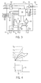
- Fig. 3 is a block diagram of the components of the controller of Fig. 1 including a microcontroller independently controlling electrical power to coils of the vacuum contactor;
- a vacuum contactor system 10 providing an example electromechanical switch system suitable for use with the present invention, includes a vacuum contactor 12 and a vacuum contactor controller 14.
- Each of these assemblies of vacuum contactor 12 may be duplicated for multiphase circuits.
- the several vacuum bottles may be actuated by a common armature 24.
- a release electromagnet 40 that, when activated, draws the armature latch 34 downward pulling roller 38 away from armature tab 26 and allowing the armature tab 26 to move away from electromagnet 28 as shown again in Fig. 1 .
- current values 86 are identified and stored to be used for operation of the coil of electromagnet 28.
- the vacuum contactor controller 14 receives an actuation signal, for example, through I/O lines 44 or serial communication channels 42, the microcontroller 48 will control the appropriate coil's power supply 60 or 62 to output an average PWM voltage to the appropriate coil to produce the current value from this table 85. If the vacuum contactor is mechanically latched, only the pull-in current for coil of electromagnet 28 is needed and the holding current may be the pull-in current to be used for coil of release electromagnet 40. Generally the current needed for coil of release electromagnet 40 does not change with changes in barometric pressure.
Landscapes
- Physics & Mathematics (AREA)
- Engineering & Computer Science (AREA)
- Electromagnetism (AREA)
- Theoretical Computer Science (AREA)
- General Physics & Mathematics (AREA)
- Power Engineering (AREA)
- Measuring Fluid Pressure (AREA)
- Furnace Details (AREA)
Applications Claiming Priority (1)
| Application Number | Priority Date | Filing Date | Title |
|---|---|---|---|
| US11/844,879 US7593211B2 (en) | 2007-08-24 | 2007-08-24 | Automatically configuring vacuum contactor |
Publications (3)
| Publication Number | Publication Date |
|---|---|
| EP2028676A2 true EP2028676A2 (fr) | 2009-02-25 |
| EP2028676A3 EP2028676A3 (fr) | 2013-03-13 |
| EP2028676B1 EP2028676B1 (fr) | 2016-03-30 |
Family
ID=40001383
Family Applications (1)
| Application Number | Title | Priority Date | Filing Date |
|---|---|---|---|
| EP08162905.7A Ceased EP2028676B1 (fr) | 2007-08-24 | 2008-08-25 | Contacteur à vide à configuration automatique |
Country Status (5)
| Country | Link |
|---|---|
| US (1) | US7593211B2 (fr) |
| EP (1) | EP2028676B1 (fr) |
| CN (1) | CN201562629U (fr) |
| AU (1) | AU2008207474B2 (fr) |
| MX (1) | MX2008010857A (fr) |
Cited By (2)
| Publication number | Priority date | Publication date | Assignee | Title |
|---|---|---|---|---|
| EP2503575A1 (fr) * | 2011-03-22 | 2012-09-26 | Schneider Electric Industries SAS | Procédé et dispositif de diagnostic d'un actionneur, et actionneur comportant un tel dispositif |
| CN107202955A (zh) * | 2017-07-27 | 2017-09-26 | 大力电工襄阳股份有限公司 | 一种真空接触器合分闸状态间接检测装置及其方法 |
Families Citing this family (8)
| Publication number | Priority date | Publication date | Assignee | Title |
|---|---|---|---|---|
| US7804038B2 (en) * | 2007-09-28 | 2010-09-28 | Rockwell Automation Technologies, Inc. | Multi-vacuum contactor control system |
| CN102426984B (zh) * | 2011-11-29 | 2013-12-04 | 福州大学 | 抗晃电智能交流接触器高频控制系统 |
| CN104483883B (zh) * | 2014-12-25 | 2017-04-05 | 南京因泰莱电器股份有限公司 | 一种继电器控制单元 |
| CA3236029A1 (fr) * | 2015-04-14 | 2016-10-14 | Hanchett Entry Systems, Inc. | Commande d'electricite destinee a un verrou de porte et methode de conservation d'energie |
| DE102015217403A1 (de) | 2015-09-11 | 2017-03-16 | Siemens Aktiengesellschaft | Schaltgerät mit einer Vakuumröhre |
| CN108667126B (zh) * | 2018-04-20 | 2021-10-08 | 科华恒盛股份有限公司 | 一种应用于ups的接触器动作控制方法、系统及ups |
| FR3099575B1 (fr) * | 2019-07-31 | 2021-06-25 | Safran Aircraft Engines | Détection automatique d’une configuration hardware d’un équipement embarqué dans un aéronef |
| AU2023467582A1 (en) * | 2023-09-25 | 2026-04-02 | Trench Germany Gmbh | High-voltage contact with infinitely variable axial height adjustment and radial longitudinal adaptation |
Family Cites Families (7)
| Publication number | Priority date | Publication date | Assignee | Title |
|---|---|---|---|---|
| US3708638A (en) * | 1970-12-14 | 1973-01-02 | Gen Electric | Vacuum type electric circuit breaker |
| DE3323861A1 (de) * | 1983-06-29 | 1985-01-03 | Siemens AG, 1000 Berlin und 8000 München | Einstellvorrichtung fuer die vorspannkraft einer feder |
| US6156989A (en) * | 1999-09-30 | 2000-12-05 | Rockwell Technologies, Llc | Multi-phase vacuum switch arrangement including an electromagnet actuating mechanism |
| US6545234B1 (en) * | 2001-12-18 | 2003-04-08 | Abb Technology | Circuit breaker with mechanical interlock |
| US7054772B2 (en) * | 2003-09-30 | 2006-05-30 | Delphi Technologies, Inc. | Apparatus and method for monitoring and compensating for variation in solenoid resistance during use |
| US7557583B2 (en) * | 2005-11-21 | 2009-07-07 | Gm Global Technology Operations, Inc. | System and method for monitoring an electrical power relay in a hybrid electric vehicle |
| US7499255B2 (en) * | 2006-01-31 | 2009-03-03 | Thomas & Betts International, Inc. | Vacuum-type electrical switching apparatus |
-
2007
- 2007-08-24 US US11/844,879 patent/US7593211B2/en active Active
-
2008
- 2008-08-22 MX MX2008010857A patent/MX2008010857A/es active IP Right Grant
- 2008-08-22 AU AU2008207474A patent/AU2008207474B2/en not_active Ceased
- 2008-08-25 EP EP08162905.7A patent/EP2028676B1/fr not_active Ceased
- 2008-08-25 CN CN2008201319885U patent/CN201562629U/zh not_active Expired - Lifetime
Non-Patent Citations (1)
| Title |
|---|
| None |
Cited By (5)
| Publication number | Priority date | Publication date | Assignee | Title |
|---|---|---|---|---|
| EP2503575A1 (fr) * | 2011-03-22 | 2012-09-26 | Schneider Electric Industries SAS | Procédé et dispositif de diagnostic d'un actionneur, et actionneur comportant un tel dispositif |
| FR2973155A1 (fr) * | 2011-03-22 | 2012-09-28 | Schneider Electric Ind Sas | Procede et dispositif de diagnostic d'un actionneur, et actionneur comportant un tel dispositif |
| US9196434B2 (en) | 2011-03-22 | 2015-11-24 | Schneider Electric Industries Sas | Method and device for performing diagnostics of an actuator, and actuator comprising one such device |
| CN107202955A (zh) * | 2017-07-27 | 2017-09-26 | 大力电工襄阳股份有限公司 | 一种真空接触器合分闸状态间接检测装置及其方法 |
| CN107202955B (zh) * | 2017-07-27 | 2023-07-25 | 大力电工襄阳股份有限公司 | 一种真空接触器合分闸状态间接检测装置及其方法 |
Also Published As
| Publication number | Publication date |
|---|---|
| US20090052107A1 (en) | 2009-02-26 |
| US7593211B2 (en) | 2009-09-22 |
| EP2028676A3 (fr) | 2013-03-13 |
| AU2008207474B2 (en) | 2011-11-24 |
| CN201562629U (zh) | 2010-08-25 |
| MX2008010857A (es) | 2009-04-15 |
| AU2008207474A1 (en) | 2009-03-12 |
| EP2028676B1 (fr) | 2016-03-30 |
Similar Documents
| Publication | Publication Date | Title |
|---|---|---|
| EP2028676B1 (fr) | Contacteur à vide à configuration automatique | |
| EP2826053B1 (fr) | Relais incluant processeur qui fournit commande et/ou de surveillance | |
| US8159807B2 (en) | Method and device for operating a switching device | |
| US20030235017A1 (en) | Spark elimination circuit for controlling relay contacts | |
| CN101640405B (zh) | 一种用于低压或中压装置的功率和控制单元 | |
| CN110488140A (zh) | 一种电磁铁故障检测电路装置及其检测方法 | |
| CN1256501A (zh) | 用于断开或闭合电磁铁的电路断路器的标准控制装置 | |
| US20180366288A1 (en) | Circuit arrangement for operating electromagnetic drive systems | |
| CN107768204A (zh) | 用于电路断路器的可控跳闸 | |
| CN109478476B (zh) | 用于中压断路器的致动器 | |
| CN115372806A (zh) | 用于监控开关设备的方法和装置 | |
| US8934208B2 (en) | Trip circuit supervision relay for low and medium voltage applications | |
| EP3312549B1 (fr) | Ensemble électrique | |
| CN109387683B (zh) | 一种交直流电压和电流信号自适应采样电路及方法 | |
| CN1068968C (zh) | 开关设备的控制装置 | |
| US9147544B2 (en) | Electromechanical switching circuit with memory | |
| CN102428417B (zh) | 电气开关设备 | |
| JP2018056116A (ja) | アクチュエータ・デバイス、関連するアクチュエータ・デバイスおよび関連するスイッチング・ユニットを制御するための方法 | |
| CN113936961B (zh) | 一种继电器过零保护方法及电路 | |
| EP3892580B1 (fr) | Actionneur de securite electronique pour un frein de securite d'ascenseur et procede de detection de la position d'un actionneur de securite electronique | |
| CN214848454U (zh) | 基于微控制器的欠压、分励脱扣器及一种电磁铁驱动电路 | |
| JP2020087593A (ja) | 真空遮断器、並びに真空遮断器の状態監視方法 | |
| US20020135380A1 (en) | Low impedance diagnostic for gun driver and method | |
| US6781810B1 (en) | Reduced tensioning time for electronically controlled switch contactors | |
| CN111292999A (zh) | 一种用于继电器的控制方法和控制系统 |
Legal Events
| Date | Code | Title | Description |
|---|---|---|---|
| PUAI | Public reference made under article 153(3) epc to a published international application that has entered the european phase |
Free format text: ORIGINAL CODE: 0009012 |
|
| AK | Designated contracting states |
Kind code of ref document: A2 Designated state(s): AT BE BG CH CY CZ DE DK EE ES FI FR GB GR HR HU IE IS IT LI LT LU LV MC MT NL NO PL PT RO SE SI SK TR |
|
| AX | Request for extension of the european patent |
Extension state: AL BA MK RS |
|
| RIN1 | Information on inventor provided before grant (corrected) |
Inventor name: DRAKE, REGINALD, A. Inventor name: MACLENNAN, DAVID SCOTT S. |
|
| PUAL | Search report despatched |
Free format text: ORIGINAL CODE: 0009013 |
|
| AK | Designated contracting states |
Kind code of ref document: A3 Designated state(s): AT BE BG CH CY CZ DE DK EE ES FI FR GB GR HR HU IE IS IT LI LT LU LV MC MT NL NO PL PT RO SE SI SK TR |
|
| AX | Request for extension of the european patent |
Extension state: AL BA MK RS |
|
| RIC1 | Information provided on ipc code assigned before grant |
Ipc: H01H 33/666 20060101ALI20130204BHEP Ipc: H01H 11/00 20060101ALI20130204BHEP Ipc: H01H 47/00 20060101AFI20130204BHEP Ipc: G01R 31/327 20060101ALI20130204BHEP Ipc: H01F 7/18 20060101ALI20130204BHEP Ipc: H01H 33/66 20060101ALI20130204BHEP Ipc: H01H 47/02 20060101ALI20130204BHEP |
|
| 17P | Request for examination filed |
Effective date: 20130910 |
|
| RBV | Designated contracting states (corrected) |
Designated state(s): AT BE BG CH CY CZ DE DK EE ES FI FR GB GR HR HU IE IS IT LI LT LU LV MC MT NL NO PL PT RO SE SI SK TR |
|
| AKX | Designation fees paid |
Designated state(s): CH DE FR LI PL |
|
| REG | Reference to a national code |
Ref country code: DE Ref legal event code: R079 Ref document number: 602008043154 Country of ref document: DE Free format text: PREVIOUS MAIN CLASS: H01H0047000000 Ipc: G01R0031060000 |
|
| RIN1 | Information on inventor provided before grant (corrected) |
Inventor name: MACLENNAN, DAVID SCOTT S. Inventor name: DRAKE, REGINALD, A. |
|
| GRAP | Despatch of communication of intention to grant a patent |
Free format text: ORIGINAL CODE: EPIDOSNIGR1 |
|
| RIC1 | Information provided on ipc code assigned before grant |
Ipc: H01H 33/666 20060101ALI20151130BHEP Ipc: H01H 47/02 20060101ALI20151130BHEP Ipc: G01R 31/06 20060101AFI20151130BHEP Ipc: H01H 11/00 20060101ALI20151130BHEP Ipc: H01F 7/18 20060101ALI20151130BHEP Ipc: H01H 33/66 20060101ALI20151130BHEP Ipc: H01H 47/00 20060101ALI20151130BHEP Ipc: G01R 31/327 20060101ALI20151130BHEP |
|
| INTG | Intention to grant announced |
Effective date: 20151218 |
|
| GRAS | Grant fee paid |
Free format text: ORIGINAL CODE: EPIDOSNIGR3 |
|
| GRAA | (expected) grant |
Free format text: ORIGINAL CODE: 0009210 |
|
| AK | Designated contracting states |
Kind code of ref document: B1 Designated state(s): CH DE FR LI PL |
|
| REG | Reference to a national code |
Ref country code: CH Ref legal event code: EP |
|
| REG | Reference to a national code |
Ref country code: DE Ref legal event code: R096 Ref document number: 602008043154 Country of ref document: DE |
|
| REG | Reference to a national code |
Ref country code: FR Ref legal event code: PLFP Year of fee payment: 9 |
|
| PG25 | Lapsed in a contracting state [announced via postgrant information from national office to epo] |
Ref country code: PL Free format text: LAPSE BECAUSE OF FAILURE TO SUBMIT A TRANSLATION OF THE DESCRIPTION OR TO PAY THE FEE WITHIN THE PRESCRIBED TIME-LIMIT Effective date: 20160330 |
|
| REG | Reference to a national code |
Ref country code: DE Ref legal event code: R097 Ref document number: 602008043154 Country of ref document: DE |
|
| PLBE | No opposition filed within time limit |
Free format text: ORIGINAL CODE: 0009261 |
|
| STAA | Information on the status of an ep patent application or granted ep patent |
Free format text: STATUS: NO OPPOSITION FILED WITHIN TIME LIMIT |
|
| 26N | No opposition filed |
Effective date: 20170103 |
|
| REG | Reference to a national code |
Ref country code: CH Ref legal event code: PL |
|
| PG25 | Lapsed in a contracting state [announced via postgrant information from national office to epo] |
Ref country code: CH Free format text: LAPSE BECAUSE OF NON-PAYMENT OF DUE FEES Effective date: 20160831 Ref country code: LI Free format text: LAPSE BECAUSE OF NON-PAYMENT OF DUE FEES Effective date: 20160831 |
|
| REG | Reference to a national code |
Ref country code: FR Ref legal event code: PLFP Year of fee payment: 10 |
|
| REG | Reference to a national code |
Ref country code: FR Ref legal event code: PLFP Year of fee payment: 11 |
|
| REG | Reference to a national code |
Ref country code: DE Ref legal event code: R079 Ref document number: 602008043154 Country of ref document: DE Free format text: PREVIOUS MAIN CLASS: G01R0031060000 Ipc: G01R0031720000 |
|
| P01 | Opt-out of the competence of the unified patent court (upc) registered |
Effective date: 20230404 |
|
| PGFP | Annual fee paid to national office [announced via postgrant information from national office to epo] |
Ref country code: FR Payment date: 20230720 Year of fee payment: 16 Ref country code: DE Payment date: 20230720 Year of fee payment: 16 |
|
| REG | Reference to a national code |
Ref country code: DE Ref legal event code: R119 Ref document number: 602008043154 Country of ref document: DE |
|
| PG25 | Lapsed in a contracting state [announced via postgrant information from national office to epo] |
Ref country code: DE Free format text: LAPSE BECAUSE OF NON-PAYMENT OF DUE FEES Effective date: 20250301 |
|
| PG25 | Lapsed in a contracting state [announced via postgrant information from national office to epo] |
Ref country code: FR Free format text: LAPSE BECAUSE OF NON-PAYMENT OF DUE FEES Effective date: 20240831 |