EP2028726A2 - Contact de conducteur interne creux pour connecteur de câble coaxial - Google Patents
Contact de conducteur interne creux pour connecteur de câble coaxial Download PDFInfo
- Publication number
- EP2028726A2 EP2028726A2 EP08005746A EP08005746A EP2028726A2 EP 2028726 A2 EP2028726 A2 EP 2028726A2 EP 08005746 A EP08005746 A EP 08005746A EP 08005746 A EP08005746 A EP 08005746A EP 2028726 A2 EP2028726 A2 EP 2028726A2
- Authority
- EP
- European Patent Office
- Prior art keywords
- contact
- plug
- inner conductor
- conductor
- diameter surface
- Prior art date
- Legal status (The legal status is an assumption and is not a legal conclusion. Google has not performed a legal analysis and makes no representation as to the accuracy of the status listed.)
- Withdrawn
Links
Images



Classifications
-
- H—ELECTRICITY
- H01—ELECTRIC ELEMENTS
- H01R—ELECTRICALLY-CONDUCTIVE CONNECTIONS; STRUCTURAL ASSOCIATIONS OF A PLURALITY OF MUTUALLY-INSULATED ELECTRICAL CONNECTING ELEMENTS; COUPLING DEVICES; CURRENT COLLECTORS
- H01R24/00—Two-part coupling devices, or either of their cooperating parts, characterised by their overall structure
- H01R24/38—Two-part coupling devices, or either of their cooperating parts, characterised by their overall structure having concentrically or coaxially arranged contacts
- H01R24/40—Two-part coupling devices, or either of their cooperating parts, characterised by their overall structure having concentrically or coaxially arranged contacts specially adapted for high frequency
- H01R24/56—Two-part coupling devices, or either of their cooperating parts, characterised by their overall structure having concentrically or coaxially arranged contacts specially adapted for high frequency specially adapted to a specific shape of cables, e.g. corrugated cables, twisted pair cables, cables with two screens or hollow cables
- H01R24/564—Corrugated cables
-
- H—ELECTRICITY
- H01—ELECTRIC ELEMENTS
- H01R—ELECTRICALLY-CONDUCTIVE CONNECTIONS; STRUCTURAL ASSOCIATIONS OF A PLURALITY OF MUTUALLY-INSULATED ELECTRICAL CONNECTING ELEMENTS; COUPLING DEVICES; CURRENT COLLECTORS
- H01R13/00—Details of coupling devices of the kinds covered by groups H01R12/70 or H01R24/00 - H01R33/00
- H01R13/02—Contact members
- H01R13/10—Sockets for co-operation with pins or blades
- H01R13/11—Resilient sockets
- H01R13/111—Resilient sockets co-operating with pins having a circular transverse section
-
- H—ELECTRICITY
- H01—ELECTRIC ELEMENTS
- H01R—ELECTRICALLY-CONDUCTIVE CONNECTIONS; STRUCTURAL ASSOCIATIONS OF A PLURALITY OF MUTUALLY-INSULATED ELECTRICAL CONNECTING ELEMENTS; COUPLING DEVICES; CURRENT COLLECTORS
- H01R24/00—Two-part coupling devices, or either of their cooperating parts, characterised by their overall structure
- H01R24/38—Two-part coupling devices, or either of their cooperating parts, characterised by their overall structure having concentrically or coaxially arranged contacts
- H01R24/40—Two-part coupling devices, or either of their cooperating parts, characterised by their overall structure having concentrically or coaxially arranged contacts specially adapted for high frequency
- H01R24/56—Two-part coupling devices, or either of their cooperating parts, characterised by their overall structure having concentrically or coaxially arranged contacts specially adapted for high frequency specially adapted to a specific shape of cables, e.g. corrugated cables, twisted pair cables, cables with two screens or hollow cables
- H01R24/566—Hollow cables
-
- H—ELECTRICITY
- H01—ELECTRIC ELEMENTS
- H01R—ELECTRICALLY-CONDUCTIVE CONNECTIONS; STRUCTURAL ASSOCIATIONS OF A PLURALITY OF MUTUALLY-INSULATED ELECTRICAL CONNECTING ELEMENTS; COUPLING DEVICES; CURRENT COLLECTORS
- H01R9/00—Structural associations of a plurality of mutually-insulated electrical connecting elements, e.g. terminal strips or terminal blocks; Terminals or binding posts mounted upon a base or in a case; Bases therefor
- H01R9/03—Connectors arranged to contact a plurality of the conductors of a multiconductor cable, e.g. tapping connections
- H01R9/05—Connectors arranged to contact a plurality of the conductors of a multiconductor cable, e.g. tapping connections for coaxial cables
-
- H—ELECTRICITY
- H01—ELECTRIC ELEMENTS
- H01R—ELECTRICALLY-CONDUCTIVE CONNECTIONS; STRUCTURAL ASSOCIATIONS OF A PLURALITY OF MUTUALLY-INSULATED ELECTRICAL CONNECTING ELEMENTS; COUPLING DEVICES; CURRENT COLLECTORS
- H01R13/00—Details of coupling devices of the kinds covered by groups H01R12/70 or H01R24/00 - H01R33/00
- H01R13/02—Contact members
- H01R13/15—Pins, blades or sockets having separate spring member for producing or increasing contact pressure
- H01R13/187—Pins, blades or sockets having separate spring member for producing or increasing contact pressure with spring member in the socket
-
- H—ELECTRICITY
- H01—ELECTRIC ELEMENTS
- H01R—ELECTRICALLY-CONDUCTIVE CONNECTIONS; STRUCTURAL ASSOCIATIONS OF A PLURALITY OF MUTUALLY-INSULATED ELECTRICAL CONNECTING ELEMENTS; COUPLING DEVICES; CURRENT COLLECTORS
- H01R13/00—Details of coupling devices of the kinds covered by groups H01R12/70 or H01R24/00 - H01R33/00
- H01R13/46—Bases; Cases
- H01R13/52—Dustproof, splashproof, drip-proof, waterproof, or flameproof cases
-
- H—ELECTRICITY
- H01—ELECTRIC ELEMENTS
- H01R—ELECTRICALLY-CONDUCTIVE CONNECTIONS; STRUCTURAL ASSOCIATIONS OF A PLURALITY OF MUTUALLY-INSULATED ELECTRICAL CONNECTING ELEMENTS; COUPLING DEVICES; CURRENT COLLECTORS
- H01R2103/00—Two poles
-
- H—ELECTRICITY
- H01—ELECTRIC ELEMENTS
- H01R—ELECTRICALLY-CONDUCTIVE CONNECTIONS; STRUCTURAL ASSOCIATIONS OF A PLURALITY OF MUTUALLY-INSULATED ELECTRICAL CONNECTING ELEMENTS; COUPLING DEVICES; CURRENT COLLECTORS
- H01R4/00—Electrically-conductive connections between two or more conductive members in direct contact, i.e. touching one another; Means for effecting or maintaining such contact; Electrically-conductive connections having two or more spaced connecting locations for conductors and using contact members penetrating insulation
- H01R4/58—Electrically-conductive connections between two or more conductive members in direct contact, i.e. touching one another; Means for effecting or maintaining such contact; Electrically-conductive connections having two or more spaced connecting locations for conductors and using contact members penetrating insulation characterised by the form or material of the contacting members
- H01R4/62—Connections between conductors of different materials; Connections between or with aluminium or steel-core aluminium conductors
Definitions
- the invention relates to inner contacts for coaxial cable connectors. More particularly the invention relates to coaxial cable connector inner contacts with improved inter modulation distortion (IMD) performance and or compatibility with hollow aluminum or bi-metal inner conductors.
- IMD inter modulation distortion
- IMD performance may be degraded when a less than optimal electrical connection is made between the inner contact and the inner conductor.
- An inner conductor contact may be skewed during installation, for example, because the inner conductor may be movable relative to the outer conductor due to the elasticity of the surrounding foam insulation.
- Prior connections to hollow inner conductor coaxial cables have applied various plug type inner contact connections inserted into the open end of the hollow inner conductor to create an electrical connection between the inner diameter surface of the hollow inner conductor and the plug. These connections may be mechanically complex and or difficult to reliably seal against moisture penetration into the hollow inner conductor.
- coaxial cables typically have inner and outer conductors made from copper and copper alloy
- the inventor has recognized that new coaxial cable configurations having a hollow aluminum and or aluminum with copper or other metallic outer coating inner conductor would reduce materials cost and overall cable weight.
- These new coaxial cable configurations are generally incompatible with prior coaxial connectors due to a creep characteristic of these softer metals and the difficulty of forming a reliable electrical connection between dissimilar metals subject to galvanic corrosion and or moisture accelerated oxidation.
- the creep and stress relaxation characteristics of softer metals make these materials an especially poor choice for hollow inner conductor inner diameter surface spring or mechanical wedge electrical interconnections with the inner contact.
- the creep characteristic of the softer metals leads to an inward and or outward flow of the inner conductor sidewall material immediately away from a spring bias applied by connection elements of the connector, degrading the quality of the electrical connection and or environmental sealing of the connection over time.
- the aluminum alloys generally have poor strength characteristics that increases the opportunity for inner conductor deformation during connector attachment, increasing the possibility of a less than uniform electrical connection with increased inter-modulation distortion (IMD).
- IMD inter-modulation distortion
- Galvanic corrosion between the aluminum and a dissimilar metal of the inner contact such as brass or copper may also contribute to degradation of the electrical and mechanical interconnection. Further, moisture penetration into the hollow inner conductor is a much greater problem with aluminum compared to copper material, because of the increased chance for corrosion of the aluminum material and or delamination of the outer diameter surface copper coating.
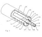
- a first embodiment of a coaxial cable connector inner contact 1 with an interface end 3 and a cable end 5 attaches to the outer diameter surface 9 of the hollow inner conductor 11 via a spring contact 13 proximate the cable end 5 dimensioned to engage the outer diameter surface 9 of the inner conductor 11.
- the spring contact 13 is here demonstrated formed as a spring basket 15 that surrounds the inner conductor 11 with a plurality of inward biased spring finger(s) 17 formed integral with cable end 5 of the inner contact 1.
- the spring finger(s) 17 may be formed with an inward projection 19 proximate the cable end 5 having an angled edge 21 facing the cable end 5 for easy insertion over the inner conductor 11 outer diameter surface 9, and a corner edge 23 at the interface end 3 operative as a barb to inhibit removal after insertion over the inner conductor 11 outer diameter surface 9.
- a plug hole 25 open to the cable end 5 is dimensioned to receive and retain the interface end 3 of a plug 27 dimensioned to insert into the hollow inner conductor 11 and seat against the inner diameter surface 29.
- the plug 27 is operative as an insertion guide during application of the inner contact 1, an environmental seal and as a supporting surface for the hollow inner conductor 11 against the inward bias of the spring contact 13 against the outer diameter surface 9.
- the plug 27 may be cost effectively formed from a non-metalic material such as a dielectric polymer, for example polytetrafluoroethylene, polyethylene, polycarbonate or other suitable plastic material.
- the plug 27 may be formed with a seal seating feature, such as an outer diameter groove 31 in which a seal 33 such as an o-ring gasket or the like may be seated, for example proximate the cable end 5 of the plug 27, to environmentally seal between the plug 27 and the inner diameter surface 29 of the inner conductor 11.
- a seal seating feature such as an outer diameter groove 31 in which a seal 33 such as an o-ring gasket or the like may be seated, for example proximate the cable end 5 of the plug 27, to environmentally seal between the plug 27 and the inner diameter surface 29 of the inner conductor 11.
- the interface end 3 of the inner contact 1 is demonstrated in figures 1-3 as a spring basket 15, according to the connector industry standard 7/16 DIN female connector interface.
- the interface end 3 may be a pin or other desired inner conductor interface and or interconnection surface according to any desired standard or proprietary coaxial connector interface, including for example, a threaded connection surface to which a further interface element may be attached.
- Figures 1-3 also demonstrate alternative coaxial cable connection end 35 configurations for attaching the inner contact 1 and a further connector assembly 7 that carries the inner contact 1 supported coaxial within a bore 37 by an insulator 39, the connector assembly 7 coupling with an outer conductor 41 of the coaxial cable 43.
- Figure 1 demonstrates the inner contact 1 configured to couple with the inner conductor 11 projecting forward of the outer conductor 41
- Figures 2 and 3 demonstrate the inner contact 1 and the supporting connector assembly 7 configured to couple with the inner conductor 11 flush with the outer conductor 41.
- the flush configuration to provide a clear area 45 for insertion of the spring contact 13 over the outer diameter surface 9 of the inner conductor 11, the mating area of coaxial cable insulation 47 is removed before assembly, for example as shown in Figure 2 .
- the connector assembly 7 configuration is dependent upon the outer conductor 41 configuration and or desired connection interface of which a wide range of configurations are well known to one skilled in the art and as such are not further described herein.
- the spring contact 13 may be configured in a wide range of alternative configurations.
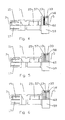
- the spring contact 13 may also be formed as at least one spring coil 55 retained within a first inner diameter groove 57 of an overlapping surface 59 of the inner contact 1. Additional inner contact 1 to inner conductor 11 environmental sealing may be added by including an inward projecting seal 33 retained, for example in a second inner diameter groove 58 around the overlapping surface 59 inner diameter 60, preferably proximate the cable end 5.
- Alternative spring contact 13 configurations include, for example, a generally U-shaped spring ( Figure 5 ) and a side mounted v-shaped spring ( Figure 6 ).
- the spring contact may be formed as an inward bend 51 of each spring finger 17 with a maximum inward projection proximate a longitudinal mid point of the spring contact 13, the cable end 5 of the spring finger(s) 17 each joined by a reinforcing ring 53 ( Figure 7 ), or allowed to move independently ( Figure 8 ).
- the coaxial cable inner conductor 11 may be helically corrugated.
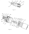
- the plug 27, for example as shown in Figures 9 and 10 may be configured with corresponding threads 61 threadable into the helical corrugations, to similarly provide support for the corrugated outer diameter surface 9 of the hollow inner conductor 11.
- the threaded plug 27 may have a seal 33 in the form of a threaded gasket portion formed with outer diameter threads 61, preferably proximate the cable end 5 of the plug.
- Figures 6 and 7 also demonstrate a plug 27 shoulder 63 formed proximate the interface end 3 against which the connection end 35 of the hollow inner conductor 11 will abut when the plug 27 is fully seated (threaded) into the hollow inner conductor 11.
- the shoulder 63 if formed on a plug 27 of dielectric material, prevents any electrical contact with the exposed aluminum connection end 35 of the inner conductor 11. Thereby, the possibility of a dissimilar metal electrical connection between the inner contact 1 and the inner conductor 11 is eliminated.
- the plug 27 may be applied to the inner conductor 11, threaded into place, for example via flat(s), a tool depression or hole 65 formed in or proximate the shoulder 63, before the plug 27 is coupled to the inner contact 1.
- the interface end 3 of the plug 27 may be formed with outward biased spring finger(s) 17 that mate with the plug hole 25 as the connector assembly 7, including the inner contact 1 is applied to the connection end 35 of the coaxial cable.
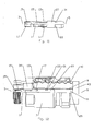
- the plug 27 is useful as an assembly guide and environmental seal, even where a conventional inner diameter surface 29 contacting spring contact or the like is applied to the inner contact 1 as shown for example in Figures 11 and 12 , correcting any initial deformation that may have occurred during cable connection end 35 preparation and minimizing the opportunity for deformation or misalignment of the inner conductor 11 during connector assembly that could lead to poor connection quality and increased IMD.
- the outer diameter surface 9 connection of the spring contact 13, supported by the plug 27 inserted within the hollow inner conductor 11 enables secure electrical connection between the inner conductor 11 and the inner contact 1 with reduced risk of electrical failure due to the inherent creep and stress deformation material characteristics of aluminum alloys.
- the inner contact 1 is especially suited for a coaxial cable with a hollow aluminum inner conductor 11 having a copper coating about the outer diameter surface 9, thereby enabling secure electrical contact without the disadvantages of direct contact electrical connections between dissimilar metals and or aluminum oxidation while availing of the lower material cost and weight of a hollow aluminum inner conductor 11 coaxial cable.
- the invention is operable via bi-metal arrangements of the spring contact 13, including for example, tin or silver coatings.
- the inner contact 1 may be incorporated into a wide range of existing coaxial connector assemblies 7 with a minimum of re-engineering and or tooling.
- Table of Parts 1 inner contact 3 interface end 5 cable end 7 connector assembly 9 outer diameter surface 11 inner conductor 13 spring contact 15 spring basket 17 spring finger 19 inward projection 21 angled edge 23 corner edge 25 plug hole 27 plug 29 inner diameter surface 31 outer diameter groove 33 seal 35 connection end 37 bore 39 insulator 41 outer conductor 43 coaxial cable 45 clear area 47 insulation 51 inward bend 53 ring 55 spring coil 57 first inner diameter groove 58 second inner diameter groove 59 overlapping surface 60 inner diameter 61 thread 63 shoulder 65 hole
Landscapes
- Coupling Device And Connection With Printed Circuit (AREA)
Applications Claiming Priority (1)
| Application Number | Priority Date | Filing Date | Title |
|---|---|---|---|
| US11/843,599 US7448906B1 (en) | 2007-08-22 | 2007-08-22 | Hollow inner conductor contact for coaxial cable connector |
Publications (2)
| Publication Number | Publication Date |
|---|---|
| EP2028726A2 true EP2028726A2 (fr) | 2009-02-25 |
| EP2028726A3 EP2028726A3 (fr) | 2009-12-30 |
Family
ID=39940754
Family Applications (1)
| Application Number | Title | Priority Date | Filing Date |
|---|---|---|---|
| EP08005746A Withdrawn EP2028726A3 (fr) | 2007-08-22 | 2008-03-27 | Contact de conducteur interne creux pour connecteur de câble coaxial |
Country Status (7)
| Country | Link |
|---|---|
| US (1) | US7448906B1 (fr) |
| EP (1) | EP2028726A3 (fr) |
| JP (1) | JP2009049009A (fr) |
| KR (1) | KR20090020469A (fr) |
| CN (1) | CN101373870A (fr) |
| BR (1) | BRPI0803429A2 (fr) |
| CA (1) | CA2631079A1 (fr) |
Families Citing this family (23)
| Publication number | Priority date | Publication date | Assignee | Title |
|---|---|---|---|---|
| US7819698B2 (en) * | 2007-08-22 | 2010-10-26 | Andrew Llc | Sealed inner conductor contact for coaxial cable connector |
| US7798847B2 (en) * | 2008-10-07 | 2010-09-21 | Andrew Llc | Inner conductor sealing insulator for coaxial connector |
| US7731529B1 (en) * | 2008-11-24 | 2010-06-08 | Andrew Llc | Connector including compressible ring for clamping a conductor of a coaxial cable and associated methods |
| US7785144B1 (en) | 2008-11-24 | 2010-08-31 | Andrew Llc | Connector with positive stop for coaxial cable and associated methods |
| US7635283B1 (en) | 2008-11-24 | 2009-12-22 | Andrew Llc | Connector with retaining ring for coaxial cable and associated methods |
| US8136234B2 (en) * | 2008-11-24 | 2012-03-20 | Andrew Llc | Flaring coaxial cable end preparation tool and associated methods |
| US7632143B1 (en) | 2008-11-24 | 2009-12-15 | Andrew Llc | Connector with positive stop and compressible ring for coaxial cable and associated methods |
| US7931499B2 (en) * | 2009-01-28 | 2011-04-26 | Andrew Llc | Connector including flexible fingers and associated methods |
| US7803018B1 (en) * | 2009-03-10 | 2010-09-28 | Andrew Llc | Inner conductor end contacting coaxial connector and inner conductor adapter kit |
| US7736180B1 (en) | 2009-03-26 | 2010-06-15 | Andrew Llc | Inner conductor wedge attachment coupling coaxial connector |
| BRPI1015143A2 (pt) * | 2009-06-05 | 2016-10-25 | Andrew Llc | conector coaxial de contato de anel deslizante. |
| EP2385585A1 (fr) * | 2010-04-16 | 2011-11-09 | Astrium Limited | Connecteur |
| US8563861B2 (en) | 2010-11-22 | 2013-10-22 | Andrew Llc | Friction weld inner conductor cap and interconnection method |
| US8365404B2 (en) | 2010-11-22 | 2013-02-05 | Andrew Llc | Method for ultrasonic welding a coaxial cable to a coaxial connector |
| US8876549B2 (en) | 2010-11-22 | 2014-11-04 | Andrew Llc | Capacitively coupled flat conductor connector |
| US8887388B2 (en) | 2010-11-22 | 2014-11-18 | Andrew Llc | Method for interconnecting a coaxial connector with a solid outer conductor coaxial cable |
| US9793660B2 (en) * | 2012-03-19 | 2017-10-17 | Holland Electronics, Llc | Shielded coaxial connector |
| US9009960B2 (en) * | 2013-01-25 | 2015-04-21 | Commscope Technologies Llc | Method of manufacturing a curved transition surface of an inner contact |
| DE102015108088A1 (de) * | 2015-05-21 | 2016-11-24 | Amad Mennekes Holding Gmbh & Co. Kg | Kontakthülse für Steckvorrichtungen |
| JP7696840B2 (ja) * | 2019-06-07 | 2025-06-23 | アプライド マテリアルズ インコーポレイテッド | シームレス電線用導管 |
| CN110518386B (zh) * | 2019-08-29 | 2024-05-17 | 中航富士达科技股份有限公司 | 一种内导体、内导体组件及连接器 |
| CN117438810A (zh) * | 2022-07-15 | 2024-01-23 | 泰科电子(上海)有限公司 | 线缆连接器 |
| CN119852778B (zh) * | 2025-03-24 | 2025-06-03 | 杭州圣铼电子电器有限公司 | 一种自锁式电缆连接器 |
Family Cites Families (17)
| Publication number | Priority date | Publication date | Assignee | Title |
|---|---|---|---|---|
| US3106599A (en) | 1961-11-10 | 1963-10-08 | Technical Appliance Corp | Expansible connector for rigid coaxial transmission line |
| DE3422549A1 (de) * | 1984-06-18 | 1985-12-19 | Georg Dr.-Ing. 8152 Feldkirchen-Westerham Spinner | Stecker fuer koaxialkabel |
| US5137470A (en) | 1991-06-04 | 1992-08-11 | Andrew Corporation | Connector for coaxial cable having a helically corrugated inner conductor |
| US5167533A (en) * | 1992-01-08 | 1992-12-01 | Andrew Corporation | Connector for coaxial cable having hollow inner conductors |
| DE4343229C2 (de) * | 1993-06-01 | 1995-04-13 | Spinner Gmbh Elektrotech | Steckverbinder für Wellrohrkoaxialkabel |
| US5545059A (en) | 1995-03-30 | 1996-08-13 | Radio Frequency Systems, Inc. | Connector for a hollow center conductor of a radio frequency cable |
| EP0741436A1 (fr) | 1995-05-02 | 1996-11-06 | HUBER & SUHNER AG KABEL-, KAUTSCHUK-, KUNSTSTOFF-WERKE | Dispositif pour connexion électrique |
| DE19533721C2 (de) * | 1995-09-12 | 1999-12-02 | Rosenberger Hochfrequenztech | Verbindungseinrichtung zum Anschluß eines Koaxialsteckers an ein Wellrohrkoaxialkabel |
| DE19654012C2 (de) | 1996-12-21 | 1999-08-12 | Cit Alcatel | Verfahren zum feuchtigkeitsdichten Anbringen eines Verbindungselements an einem Hochfrequenzkabel |
| SE9800448L (sv) | 1998-02-17 | 1999-04-12 | Teracom Components Ab | Kontaktanordning för högfrekvenskablar |
| US6332808B1 (en) | 1999-09-22 | 2001-12-25 | Mitsubishi Cable Industries, Ltd. | Connector structure |
| JP3403985B2 (ja) | 1999-12-16 | 2003-05-06 | 三菱電線工業株式会社 | 同軸ケーブル用コネクタ |
| US7134189B2 (en) * | 2002-09-12 | 2006-11-14 | Andrew Corporation | Coaxial cable connector and tool and method for connecting a coaxial cable |
| US6802739B2 (en) | 2003-01-16 | 2004-10-12 | Corning Gilbert Inc. | Coaxial cable connector |
| US6926555B2 (en) | 2003-10-09 | 2005-08-09 | Radio Frequency Systems, Inc. | Tuned radio frequency coaxial connector |
| US6863565B1 (en) | 2004-07-13 | 2005-03-08 | Palco Connector Incorporated | Constant impedance bullet connector for a semi-rigid coaxial cable |
| DE102005061672B3 (de) * | 2005-12-22 | 2007-03-22 | Spinner Gmbh | Koaxialer Steckverbinder |
-
2007
- 2007-08-22 US US11/843,599 patent/US7448906B1/en not_active Expired - Fee Related
-
2008
- 2008-03-27 EP EP08005746A patent/EP2028726A3/fr not_active Withdrawn
- 2008-05-09 CA CA002631079A patent/CA2631079A1/fr not_active Abandoned
- 2008-05-30 KR KR1020080050923A patent/KR20090020469A/ko not_active Withdrawn
- 2008-07-21 BR BRPI0803429-0A patent/BRPI0803429A2/pt not_active IP Right Cessation
- 2008-07-31 JP JP2008198713A patent/JP2009049009A/ja not_active Withdrawn
- 2008-08-19 CN CNA2008101474777A patent/CN101373870A/zh active Pending
Also Published As
| Publication number | Publication date |
|---|---|
| CN101373870A (zh) | 2009-02-25 |
| CA2631079A1 (fr) | 2009-02-22 |
| JP2009049009A (ja) | 2009-03-05 |
| EP2028726A3 (fr) | 2009-12-30 |
| KR20090020469A (ko) | 2009-02-26 |
| BRPI0803429A2 (pt) | 2009-11-10 |
| US7448906B1 (en) | 2008-11-11 |
Similar Documents
| Publication | Publication Date | Title |
|---|---|---|
| US7448906B1 (en) | Hollow inner conductor contact for coaxial cable connector | |
| US7819698B2 (en) | Sealed inner conductor contact for coaxial cable connector | |
| US7275957B1 (en) | Axial compression electrical connector for annular corrugated coaxial cable | |
| US6840803B2 (en) | Crimp connector for corrugated cable | |
| US8622762B2 (en) | Blind mate capacitively coupled connector | |
| US8622768B2 (en) | Connector with capacitively coupled connector interface | |
| US6848941B2 (en) | Low cost, high performance cable-connector system and assembly method | |
| US7806724B2 (en) | Coaxial connector for cable with a solid outer conductor | |
| US7044785B2 (en) | Connector and coaxial cable with outer conductor cylindrical section axial compression connection | |
| US7993159B2 (en) | Compression connector for coaxial cable | |
| US7753705B2 (en) | Flexible RF seal for coaxial cable connector | |
| US8007314B2 (en) | Compression connector for coaxial cable | |
| US8177583B2 (en) | Compression connector for coaxial cable | |
| US7217154B2 (en) | Connector with outer conductor axial compression connection and method of manufacture | |
| US8292661B2 (en) | Phone plug connector device | |
| WO2010054026A2 (fr) | Connecteur coaxial anti-rotation | |
| US20140134875A1 (en) | RF Isolated Capacitively Coupled Connector | |
| US12494610B2 (en) | Connector for providing more reliable signal propagation by maintaining conductor pin contact at certain perimeter portions thereof | |
| EP2777098B1 (fr) | Connecteur à couplage capacitif à assemblage à l'aveugle | |
| EP3832811B1 (fr) | Ensembles des câbles coaxiaux avec des éléments de pincement et de préhension | |
| JPS59134577A (ja) | 半剛性同軸ケ−ブルのための無半田コネクタ | |
| CN103843207B (zh) | 盲配式电容耦合连接器 |
Legal Events
| Date | Code | Title | Description |
|---|---|---|---|
| PUAI | Public reference made under article 153(3) epc to a published international application that has entered the european phase |
Free format text: ORIGINAL CODE: 0009012 |
|
| AK | Designated contracting states |
Kind code of ref document: A2 Designated state(s): AT BE BG CH CY CZ DE DK EE ES FI FR GB GR HR HU IE IS IT LI LT LU LV MC MT NL NO PL PT RO SE SI SK TR |
|
| AX | Request for extension of the european patent |
Extension state: AL BA MK RS |
|
| RIN1 | Information on inventor provided before grant (corrected) |
Inventor name: ISLAM, NAHID |
|
| PUAL | Search report despatched |
Free format text: ORIGINAL CODE: 0009013 |
|
| AK | Designated contracting states |
Kind code of ref document: A3 Designated state(s): AT BE BG CH CY CZ DE DK EE ES FI FR GB GR HR HU IE IS IT LI LT LU LV MC MT NL NO PL PT RO SE SI SK TR |
|
| AX | Request for extension of the european patent |
Extension state: AL BA MK RS |
|
| RIC1 | Information provided on ipc code assigned before grant |
Ipc: H01R 13/646 20060101ALI20091123BHEP Ipc: H01R 13/11 20060101ALI20091123BHEP Ipc: H01R 9/05 20060101AFI20091123BHEP |
|
| 17P | Request for examination filed |
Effective date: 20100317 |
|
| AKX | Designation fees paid |
Designated state(s): AT BE BG CH CY CZ DE DK EE ES FI FR GB GR HR HU IE IS IT LI LT LU LV MC MT NL NO PL PT RO SE SI SK TR |
|
| 17Q | First examination report despatched |
Effective date: 20111019 |
|
| STAA | Information on the status of an ep patent application or granted ep patent |
Free format text: STATUS: THE APPLICATION IS DEEMED TO BE WITHDRAWN |
|
| 18D | Application deemed to be withdrawn |
Effective date: 20111001 |