EP2029039B1 - Dispositif de découpage et de coagulation de tissus - Google Patents
Dispositif de découpage et de coagulation de tissus Download PDFInfo
- Publication number
- EP2029039B1 EP2029039B1 EP07765344A EP07765344A EP2029039B1 EP 2029039 B1 EP2029039 B1 EP 2029039B1 EP 07765344 A EP07765344 A EP 07765344A EP 07765344 A EP07765344 A EP 07765344A EP 2029039 B1 EP2029039 B1 EP 2029039B1
- Authority
- EP
- European Patent Office
- Prior art keywords
- gripping
- cutting
- application device
- instrument
- coagulation
- Prior art date
- Legal status (The legal status is an assumption and is not a legal conclusion. Google has not performed a legal analysis and makes no representation as to the accuracy of the status listed.)
- Not-in-force
Links
- 238000005520 cutting process Methods 0.000 title claims abstract description 48
- 238000005345 coagulation Methods 0.000 title claims abstract description 30
- 230000015271 coagulation Effects 0.000 title claims abstract description 30
- 238000011010 flushing procedure Methods 0.000 claims description 9
- 230000007935 neutral effect Effects 0.000 claims description 9
- 239000012530 fluid Substances 0.000 claims description 7
- 210000001519 tissue Anatomy 0.000 description 23
- 238000000034 method Methods 0.000 description 15
- 238000001356 surgical procedure Methods 0.000 description 13
- 239000007788 liquid Substances 0.000 description 11
- 230000000740 bleeding effect Effects 0.000 description 9
- 210000002741 palatine tonsil Anatomy 0.000 description 8
- 230000008569 process Effects 0.000 description 6
- 230000001112 coagulating effect Effects 0.000 description 4
- 238000009297 electrocoagulation Methods 0.000 description 4
- 238000000926 separation method Methods 0.000 description 4
- 239000004696 Poly ether ether ketone Substances 0.000 description 3
- 239000008280 blood Substances 0.000 description 3
- 210000004369 blood Anatomy 0.000 description 3
- 239000002775 capsule Substances 0.000 description 3
- 230000008859 change Effects 0.000 description 3
- 238000002357 laparoscopic surgery Methods 0.000 description 3
- 229920002530 polyetherether ketone Polymers 0.000 description 3
- 230000008901 benefit Effects 0.000 description 2
- JUPQTSLXMOCDHR-UHFFFAOYSA-N benzene-1,4-diol;bis(4-fluorophenyl)methanone Chemical compound OC1=CC=C(O)C=C1.C1=CC(F)=CC=C1C(=O)C1=CC=C(F)C=C1 JUPQTSLXMOCDHR-UHFFFAOYSA-N 0.000 description 2
- 210000004204 blood vessel Anatomy 0.000 description 2
- 230000018044 dehydration Effects 0.000 description 2
- 238000006297 dehydration reaction Methods 0.000 description 2
- 239000004744 fabric Substances 0.000 description 2
- 239000012811 non-conductive material Substances 0.000 description 2
- 238000007483 tonsillectomy Methods 0.000 description 2
- 230000007704 transition Effects 0.000 description 2
- 206010040844 Skin exfoliation Diseases 0.000 description 1
- FAPWRFPIFSIZLT-UHFFFAOYSA-M Sodium chloride Chemical compound [Na+].[Cl-] FAPWRFPIFSIZLT-UHFFFAOYSA-M 0.000 description 1
- 238000012084 abdominal surgery Methods 0.000 description 1
- 210000001367 artery Anatomy 0.000 description 1
- 210000001124 body fluid Anatomy 0.000 description 1
- 239000010839 body fluid Substances 0.000 description 1
- 238000007796 conventional method Methods 0.000 description 1
- 230000035618 desquamation Effects 0.000 description 1
- 230000000694 effects Effects 0.000 description 1
- 210000001559 fluids and secretion Anatomy 0.000 description 1
- 230000004927 fusion Effects 0.000 description 1
- 230000002439 hemostatic effect Effects 0.000 description 1
- 239000012212 insulator Substances 0.000 description 1
- 230000002452 interceptive effect Effects 0.000 description 1
- 238000002324 minimally invasive surgery Methods 0.000 description 1
- 210000003300 oropharynx Anatomy 0.000 description 1
- 239000002504 physiological saline solution Substances 0.000 description 1
- 239000011343 solid material Substances 0.000 description 1
- 239000000243 solution Substances 0.000 description 1
- 210000002023 somite Anatomy 0.000 description 1
- 229910000811 surgical stainless steel Inorganic materials 0.000 description 1
- 230000000451 tissue damage Effects 0.000 description 1
- 231100000827 tissue damage Toxicity 0.000 description 1
- 238000003325 tomography Methods 0.000 description 1
- 230000032258 transport Effects 0.000 description 1
Images


Classifications
-
- A—HUMAN NECESSITIES
- A61—MEDICAL OR VETERINARY SCIENCE; HYGIENE
- A61B—DIAGNOSIS; SURGERY; IDENTIFICATION
- A61B18/00—Surgical instruments, devices or methods for transferring non-mechanical forms of energy to or from the body
- A61B18/04—Surgical instruments, devices or methods for transferring non-mechanical forms of energy to or from the body by heating
- A61B18/12—Surgical instruments, devices or methods for transferring non-mechanical forms of energy to or from the body by heating by passing a current through the tissue to be heated, e.g. high-frequency current
- A61B18/14—Probes or electrodes therefor
- A61B18/1442—Probes having pivoting end effectors, e.g. forceps
-
- A—HUMAN NECESSITIES
- A61—MEDICAL OR VETERINARY SCIENCE; HYGIENE
- A61B—DIAGNOSIS; SURGERY; IDENTIFICATION
- A61B18/00—Surgical instruments, devices or methods for transferring non-mechanical forms of energy to or from the body
- A61B2018/00571—Surgical instruments, devices or methods for transferring non-mechanical forms of energy to or from the body for achieving a particular surgical effect
- A61B2018/00589—Coagulation
-
- A—HUMAN NECESSITIES
- A61—MEDICAL OR VETERINARY SCIENCE; HYGIENE
- A61B—DIAGNOSIS; SURGERY; IDENTIFICATION
- A61B18/00—Surgical instruments, devices or methods for transferring non-mechanical forms of energy to or from the body
- A61B2018/00571—Surgical instruments, devices or methods for transferring non-mechanical forms of energy to or from the body for achieving a particular surgical effect
- A61B2018/00601—Cutting
-
- A—HUMAN NECESSITIES
- A61—MEDICAL OR VETERINARY SCIENCE; HYGIENE
- A61B—DIAGNOSIS; SURGERY; IDENTIFICATION
- A61B2218/00—Details of surgical instruments, devices or methods for transferring non-mechanical forms of energy to or from the body
- A61B2218/001—Details of surgical instruments, devices or methods for transferring non-mechanical forms of energy to or from the body having means for irrigation and/or aspiration of substances to and/or from the surgical site
- A61B2218/002—Irrigation
-
- A—HUMAN NECESSITIES
- A61—MEDICAL OR VETERINARY SCIENCE; HYGIENE
- A61B—DIAGNOSIS; SURGERY; IDENTIFICATION
- A61B2218/00—Details of surgical instruments, devices or methods for transferring non-mechanical forms of energy to or from the body
- A61B2218/001—Details of surgical instruments, devices or methods for transferring non-mechanical forms of energy to or from the body having means for irrigation and/or aspiration of substances to and/or from the surgical site
- A61B2218/002—Irrigation
- A61B2218/003—Irrigation using a spray or a foam
-
- A—HUMAN NECESSITIES
- A61—MEDICAL OR VETERINARY SCIENCE; HYGIENE
- A61B—DIAGNOSIS; SURGERY; IDENTIFICATION
- A61B2218/00—Details of surgical instruments, devices or methods for transferring non-mechanical forms of energy to or from the body
- A61B2218/001—Details of surgical instruments, devices or methods for transferring non-mechanical forms of energy to or from the body having means for irrigation and/or aspiration of substances to and/or from the surgical site
- A61B2218/007—Aspiration
Definitions
- the invention relates to an instrument for the separation or removal of body tissue by means of electrotomy and the sclerosing of body tissue and the bleeding of bleeding by means of electrocoagulation.
- the electrosurgical desquamation of tissue or the stopping of bleeding by means of high-frequency current is also a procedure established in surgery and other medical disciplines.
- the instruments used for this purpose are as gripping instruments such. As tweezers or forceps executed.
- large-area electrodes are attached, which are at different (bipolar) or the same (monopolar) potential.
- the piece of tissue to be sclerosed or the end of the blood vessel to be closed is located between the electrodes at the distal end of the gripping instrument.
- the high frequency current flows between these electrodes and a return electrode attached to the patient elsewhere.
- the bipolar technique the high frequency current flows between the two electrodes at the distal end of the legs of the gripping instrument.
- Cutting by means of wire or lancet electrodes located at the end of a handle and coagulation with gripping instruments are the most widely used high frequency surgical techniques.
- the cutting electrode and the coagulation grasping instrument are two different instruments which often need to be changed during surgery or operated by two operators.
- Interventions in the mouth and throat are performed only by a surgeon because of the available low viewing angle in this natural body opening. This means that a change of instrument is necessary in the transition from cutting to coagulation in the current state of the art. It is often the case that, when performing a high-frequency incision and severing a larger blood vessel, the hemostatic property of the coagulated incision cavity is insufficient and, in addition, bleeding must be stopped with a bipolar or monopolar gripping instrument. In such a case, a very rapid change from the cutting to the coagulating instrument is very important.
- Out DE 40 17 626 A1 is a combination of a cutting and a coagulating instrument known.
- the invention has for its object to provide an application device for the electrotomy, which avoids the disadvantages of the prior art as possible.
- an electrosurgical instrument which is designed as a gripping instrument and combines the functions cutting, coagulation and gripping in an instrument.
- the instrument is designed as a gripping instrument with two gripping arms which are movable relative to one another and each have at least two electrodes, namely at least one coagulation electrode and at least one cutting electrode, at their distal end.
- a respective cutting electrode is formed as arranged on the outside of a respective distal end of a gripping arm wire, which thus acts as a cutting wire.
- the grasping instrument with closed gripping arms can be used in a manner familiar to the physician, such as a mono- or bipolar cutting instrument of conventional design.
- the coagulation electrodes are preferably designed as conductive surfaces on mutually facing inner surfaces at the distal ends of the gripping arms.
- a mechanical travel limit for the movement of the gripping arms preferably prevents mutual contact of the coagulation electrodes forming conductive surfaces and thus an unwanted short circuit.
- the mechanical path limitation is preferably formed by a directed in the direction of the respective other gripping arm projection on an inner surface of a gripping arm.
- At least one of the gripper arms has a suction channel with a suction opening in the region of the distal end of the gripper arm, which is connected to a suction system and adapted to suck liquid in the region of the distal end of the gripper arm.
- the suction channel serves to suck blood or other body fluid that collects at the site of intervention.
- At least one of the gripping arms preferably has a flushing channel which opens in an open end in the vicinity of the distal end of the gripping arm and is designed such that it has its proximal end connected to a Rinse fluid source is connectable and flushing fluid can exit via its open mouth at the distal end.
- a flushing channel With the help of such a flushing channel, the surgical site can be rinsed with rinsing liquid.
- the cutting electrodes are preferably connected in parallel with each other.
- the application device preferably has a separate neutral electrode which is to be connected to another pole of a cutting current generator, as the two cutting electrodes. In this way, the application device operates as a monopolar cutting instrument.
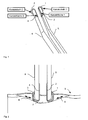
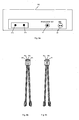
- FIG. 1 shows an electrosurgical instrument according to the invention, which is similar to a bipolar or monopolar forceps or forceps constructed, and on inner sides of distal ends of gripping arms forming legs 5 and 6 large-area electrodes 2 and 4 for tissue coagulation, which in FIG. 1 Also referred to as contact surfaces 1 and 2.
- On outsides of the distal Ends of the legs 5 and 6 are cutting wires 1, 3 mounted in FIG. 1 Also referred to as contact wire 1 and 2.
- FIGS. 9a to e also depicted:
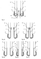
- the high-frequency surgery generator 16 off FIG. 9a has a terminal 21 a and 21 b for bipolar coagulation (bipolar coag) and a monopolar cut connector 22 and therefore allows the circuit variants K1 and S11 to S13 when operated with a surgical instrument as described in US Pat FIG. 9b is shown.
- a total of four connection contacts 24a, 24b, 25a and 25b are provided, which allow each of the electrodes 1 to 4 individually to connect to a high-frequency surgery generator.
- the high-frequency surgery generator off FIG. 9a in conjunction with a surgical instrument such as in FIG. 9c Shown allows the circuit variants K1 and S13.
- Both cutting wires 1 and 3 are connected to a common terminal contact 24 at the proximal end of the instrument and therefore connected in parallel.
- the high-frequency surgery generator 16 has a terminal 23 for connecting a neutral electrode (see Figures 9d or 9e ) or a connecting cable for such a neutral electrode (see FIG. 11 ).
- FIG. 9d and 9e each show in particular for the monopolar tissue cutting suitable neutral electrodes, and indeed shows FIG. 9d a surface electrode 17 as a neutral electrode and FIG. 9e a neutral electrode in the form of tweezers 18.
- FIG. 2 shows an exemplary cutting process in which takes place by the guide 8, the instrument on the outside cutting wires 1 and 3 with light contact of the fabric 9 along the cutting edge 7 of the cutting process.
- FIG. 3 shows an exemplary coagulation process in which the tissue 9 to be coagulated is gripped in the direction 10 between the contact surfaces 2 and 4 on the inside of the instrument with slight pressure.
- FIGS. 4a and 4b show a preferred embodiment in which the instrument is provided with a short circuit fuse 11.
- This short-circuit fuse 11 causes a mechanical path limitation and ensures that in the closed state of the instrument, a minimal gap between the two contact surfaces 2 and 4 is present and thus there is no direct metallic contact between the two contact surfaces 2 and 4.
- the mechanical travel limit can be arranged both immediately adjacent to the contact surfaces 2 and 4, as well as at any other point of the movable legs 5 and 6.
- FIGS. 5a to 5c show various embodiments of the arrangement of the contact surfaces.
- the pads 2 and 4 are mounted on the distal ends of the legs 5 and 6, the legs being made of a non-conductive material (eg, PEEK).
- the instrument consists of conductive solid material (eg surgical steel, V2A), except for the contact surfaces 2 and 4 the instrument is coated with an insulator (eg made of polyacrylic, PA).
- the contact surfaces 2 and 4 are fitted into the distal ends of the legs 5 and 6, the legs being made of a non-conductive material (eg polyetheretherketone, PEEK).
- tissue damage can release the body's own fluids and secretions, which then collect at the site to be operated on and thus have a disruptive effect on the surgical process.
- a suction instrument is guided to the site to be operated, which on the one hand occupies space at the site to be operated and obstructs the operation and, on the other hand, is also guided separately by another person got to.
- the OP for aspirating the fluids even has to be interrupted because there is not enough space to bring the aspiration and the surgical instrument to the surgical site at the same time.
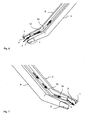
- FIG. 6 shows a preferred embodiment in which the instrument is provided with a suction channel 13, which makes a separate Absauginstrument superfluous.
- the suction channel 13 has an open mouth as a suction opening in the region of the distal ends of the legs 5 and 6, so that the unwanted and interfering liquids are sucked directly into the work area. This is done in parallel with normal surgical work.
- the suction channel 13 transports the liquid 12 from the suction port on one of the two legs 5 and 6 to an open proximal end of the suction channel in an area of the instrument remote from the distal end. At its proximal open end, the suction channel 13 is to be connected to a suction system customary in the operating theater.
- the tissue may dry out during treatment.
- the transfer resistance from the tissue to the electrosurgical instruments as well as the resistance of the tissue itself increases with increasing dehydration and the process does not work properly.
- the process must be interrupted to wet the tissue with an ionizing, biocompatible liquid (eg, sterile saline solution).
- FIG. 7 shows a preferred embodiment in which the instrument is provided with an integrated humidification system.
- This humidification system comprises a flushing channel 15 with an open mouth as an outlet opening in the region of the distal ends of the legs 5 and 6, so that ionizing liquid 14 can be metered directly into the working area. This can thus be done in parallel to the normal OP process.
- the flushing channel 15 for the liquid 14 extends along one of the two legs 5 and 6 and is to be connected in the region of the instrument, which is remote from the distal ends, with a metering system customary in the OP for such liquids.
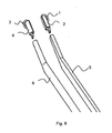
- FIG. 8 shows that the distal ends of the legs 5 and 6, which comprise the cutting wires 1 and 3 and the large-area electrodes 2 and 4, can be made interchangeable, so as to allow reuse of the rest of the instrument after surgery after replacement of the distal ends.
- the combination of high-frequency cutting and high-frequency coagulation in one instrument offers enormous advantages.
- the tonsil is slowly dissolved out of its capsule.
- the surgeon slowly works his way down to the tonsil, between the tonsil and the tonsil capsule.
- the tonsil is pulled out of the tonsil bed with tweezers medianly.
- the tweezers can simultaneously have the function of a return electrode (see Fig. 9e ).
- Small bleeding from capillary vessels are stopped immediately by the coagulating effect of the HF-cut on the cut edges.
- the tonsil is removed at the lower pole, also by an HF cut.
Landscapes
- Health & Medical Sciences (AREA)
- Surgery (AREA)
- Engineering & Computer Science (AREA)
- Life Sciences & Earth Sciences (AREA)
- Biomedical Technology (AREA)
- Otolaryngology (AREA)
- Nuclear Medicine, Radiotherapy & Molecular Imaging (AREA)
- Plasma & Fusion (AREA)
- Physics & Mathematics (AREA)
- Heart & Thoracic Surgery (AREA)
- Medical Informatics (AREA)
- Molecular Biology (AREA)
- Animal Behavior & Ethology (AREA)
- General Health & Medical Sciences (AREA)
- Public Health (AREA)
- Veterinary Medicine (AREA)
- Surgical Instruments (AREA)
Abstract
Claims (9)
- Dispositif d'application pour la découpe électrochirurgicale et la coagulation de tissu corporel, lequel dispositif est réalisé sous la forme d'un instrument de préhension comportant deux bras de préhension (5, 6) qui sont mobiles l'un par rapport à l'autre et qui comportent chacun à leur extrémité distale au moins deux électrodes, à savoir au moins une électrode de coagulation (2 ; 4) et au moins une électrode de découpe (1 ; 3),
caractérisé en ce que l'électrode de découpe respective (1, 3) est conformée en fil disposé du côté extérieur d'une extrémité distale respective d'un bras de préhension (5 ; 6). - Dispositif d'application selon la revendication 1, caractérisé en ce que les électrodes de coagulation (2, 4) sont réalisées sous la forme de surfaces conductrices, dont les faces internes sont dirigées l'une vers l'autre, au niveau des extrémités distales des bras de préhension (5, 6).
- Dispositif d'application selon la revendication 2, caractérisé en ce que l'instrument de préhension présente une limitation de course mécanique (11), destinée à limiter le déplacement des bras de préhension (5, 6), qui est conformée de façon à empêcher les surfaces conductrices, formant les électrodes de coagulation, de venir en contact l'une avec l'autre au niveau des extrémités distales des bras de préhension (5, 6).
- Dispositif d'application selon la revendication 3, caractérisé en ce que la limitation de course mécanique (11) est formée par une saillie, orientée en direction de l'autre bras de préhension (5 ; 6), sur une face intérieure d'un bras de préhension (6 ; 5).
- Dispositif d'application selon l'une des revendications 1 à 4, caractérisé en ce que au moins un des bras de préhension (5, 6) possède un canal d'aspiration (15) présentant une embouchure ouverte dans la région de l'extrémité distale du bras de préhension (5 ; 6) qui peut être raccordée à un système d'aspiration et qui est conformée pour aspirer un liquide dans la région de l'extrémité distale du bras de préhension (5 ; 6).
- Dispositif d'application selon la revendication 5, caractérisé en ce que au moins un des bras de préhension (5, 6) possède un canal de lavage (15) qui débouche dans une extrémité ouverte à proximité de l'extrémité distale du bras de préhension (5 ; 6) et qui est conformé de façon à pouvoir être raccordé, à son extrémité proximale, à une source de liquide de lavage et de façon à ce que le liquide de lavage puisse sortir par son embouchure ouverte à l'extrémité distale.
- Dispositif d'application selon la revendication 1, caractérisé en ce que les électrodes de découpe sont montées en parallèle.
- Dispositif d'application selon la revendication 7, caractérisé par une électrode neutre séparée (17 ; 18) qui peut être reliée à un pôle d'un générateur à hautes fréquences (16) différent du pôle des deux électrodes de découpe (1, 3) montées en parallèle.
- Dispositif d'application selon la revendication 8, caractérisé en ce que l'électrode neutre séparée est conformée en pinces électrochirurgicales (18).
Applications Claiming Priority (2)
| Application Number | Priority Date | Filing Date | Title |
|---|---|---|---|
| DE102006027150A DE102006027150A1 (de) | 2006-06-08 | 2006-06-08 | Vorrichtung zum Schneiden und Koagulieren von Gewebe |
| PCT/EP2007/055669 WO2007141337A2 (fr) | 2006-06-08 | 2007-06-08 | Dispositif de découpage et de coagulation de tissus |
Publications (2)
| Publication Number | Publication Date |
|---|---|
| EP2029039A2 EP2029039A2 (fr) | 2009-03-04 |
| EP2029039B1 true EP2029039B1 (fr) | 2010-12-15 |
Family
ID=38562847
Family Applications (1)
| Application Number | Title | Priority Date | Filing Date |
|---|---|---|---|
| EP07765344A Not-in-force EP2029039B1 (fr) | 2006-06-08 | 2007-06-08 | Dispositif de découpage et de coagulation de tissus |
Country Status (6)
| Country | Link |
|---|---|
| US (1) | US20100087814A1 (fr) |
| EP (1) | EP2029039B1 (fr) |
| JP (1) | JP2009539448A (fr) |
| CN (1) | CN101460110B (fr) |
| DE (2) | DE102006027150A1 (fr) |
| WO (1) | WO2007141337A2 (fr) |
Cited By (1)
| Publication number | Priority date | Publication date | Assignee | Title |
|---|---|---|---|---|
| WO2021259906A1 (fr) | 2020-06-24 | 2021-12-30 | Robert Bosch Gmbh | Instrument chirurgical |
Families Citing this family (33)
| Publication number | Priority date | Publication date | Assignee | Title |
|---|---|---|---|---|
| GB2472216A (en) * | 2009-07-28 | 2011-02-02 | Gyrus Medical Ltd | Bipolar electrosurgical instrument with four electrodes |
| EP3991678B1 (fr) * | 2010-10-01 | 2024-12-04 | Applied Medical Resources Corporation | Instruments électrochirurgicaux et connexions à ceux-ci |
| DE102010060336B4 (de) * | 2010-11-04 | 2015-03-26 | Erbe Elektromedizin Gmbh | Elektrodeneinrichtung eines elektrochirurgischen Instruments |
| EP2540242B1 (fr) * | 2011-06-28 | 2014-05-21 | Lina Medical ApS | Instrument électrochirurgical et dispositif pour ledit instrument |
| US8968307B2 (en) | 2011-08-18 | 2015-03-03 | Covidien Lp | Surgical forceps |
| US8968317B2 (en) | 2011-08-18 | 2015-03-03 | Covidien Lp | Surgical forceps |
| US8685056B2 (en) | 2011-08-18 | 2014-04-01 | Covidien Lp | Surgical forceps |
| US9023035B2 (en) | 2012-01-06 | 2015-05-05 | Covidien Lp | Monopolar pencil with integrated bipolar/ligasure tweezers |
| GB2500882B (en) * | 2012-04-02 | 2017-10-04 | Gyrus Medical Ltd | Electrosurgical instrument |
| DE102012012167A1 (de) * | 2012-06-19 | 2013-12-19 | Sutter Medizintechnik Gmbh | Koagulationszange mit einem Rohrschaft |
| US9204921B2 (en) * | 2012-12-13 | 2015-12-08 | Cook Medical Technologies Llc | RF energy controller and method for electrosurgical medical devices |
| US9901389B2 (en) | 2013-03-15 | 2018-02-27 | Gyrus Acmi, Inc. | Offset forceps |
| EP2967741B1 (fr) | 2013-03-15 | 2018-02-21 | Gyrus Acmi Inc. | Dispositif électrochirurgical de combinaison |
| JP2016510633A (ja) | 2013-03-15 | 2016-04-11 | ジャイラス エーシーエムアイ インク | 電気手術器具 |
| EP2974684B1 (fr) | 2013-03-15 | 2017-08-30 | Gyrus ACMI, Inc. | Dispositif électrochirurgical combiné |
| US20140276797A1 (en) | 2013-03-15 | 2014-09-18 | GYRUS ACMI, INC., d/b/a Olympus Surgical Technologies America | Combination electrosurgical device |
| CN103393465B (zh) * | 2013-08-01 | 2015-09-02 | 北京迈迪顶峰医疗科技有限公司 | 一种射频消融装置 |
| US10517626B2 (en) * | 2013-08-07 | 2019-12-31 | Cornell University | Semiconductor tweezers and instrumentation for tissue detection and characterization |
| CN103876832B (zh) * | 2014-04-16 | 2017-01-25 | 常州市延陵电子设备有限公司 | 双极微创切凝镊 |
| US10258404B2 (en) | 2014-04-24 | 2019-04-16 | Gyrus, ACMI, Inc. | Partially covered jaw electrodes |
| WO2016028882A1 (fr) | 2014-08-20 | 2016-02-25 | GYRUS ACMI, INC. (d/b/a OLYMPUS SURGICAL TECHNOLOGIES AMERICA) | Dispositif électrochirurgical combiné multimode |
| GB201500716D0 (en) * | 2015-01-16 | 2015-03-04 | Gyrus Medical Ltd | Electrosurgical instrument |
| CN107405168B (zh) | 2015-03-23 | 2020-05-05 | 捷锐士阿希迈公司(以奥林巴斯美国外科技术名义) | 具有血管切断能力的医用夹钳 |
| US10631918B2 (en) | 2015-08-14 | 2020-04-28 | Covidien Lp | Energizable surgical attachment for a mechanical clamp |
| WO2018033931A1 (fr) * | 2016-08-16 | 2018-02-22 | Xcellance Medical Technologies Pvt. Ltd. | Instrument électrochirurgical bipolaire de coupe et de coagulation |
| US11534231B2 (en) * | 2017-08-22 | 2022-12-27 | CovidienLP | Energy-based surgical instruments and systems configured to minimize thermal spread |
| US10667834B2 (en) | 2017-11-02 | 2020-06-02 | Gyrus Acmi, Inc. | Bias device for biasing a gripping device with a shuttle on a central body |
| US11383373B2 (en) | 2017-11-02 | 2022-07-12 | Gyms Acmi, Inc. | Bias device for biasing a gripping device by biasing working arms apart |
| US11298801B2 (en) | 2017-11-02 | 2022-04-12 | Gyrus Acmi, Inc. | Bias device for biasing a gripping device including a central body and shuttles on the working arms |
| CN108814682B (zh) * | 2018-04-20 | 2020-05-12 | 陇东学院 | 普外科手术创伤护理仪 |
| DE102019108141A1 (de) * | 2019-03-28 | 2020-10-01 | Karl Storz Se & Co. Kg | Bipolares elektrochirurgisches Werkzeug |
| FR3112279B1 (fr) * | 2020-07-08 | 2022-09-09 | Magnitude Surgical | Pince electro-chirurgicale comprenant un dispositif d’aspiration |
| US20230285065A1 (en) * | 2020-08-31 | 2023-09-14 | Covidien Lp | Electrosurgical instruments including thermal cutting elements |
Family Cites Families (14)
| Publication number | Priority date | Publication date | Assignee | Title |
|---|---|---|---|---|
| US2004559A (en) * | 1932-11-22 | 1935-06-11 | Wappler Frederick Charles | Method and instrument for electrosurgical treatment of tissue |
| US4492231A (en) * | 1982-09-17 | 1985-01-08 | Auth David C | Non-sticking electrocautery system and forceps |
| FR2647683B1 (fr) * | 1989-05-31 | 1993-02-12 | Kyocera Corp | Dispositif d'etanchement/coagulation de sang hors de vaisseaux sanguins |
| DE4032471C2 (de) * | 1990-10-12 | 1997-02-06 | Delma Elektro Med App | Elektrochirurgische Vorrichtung |
| DE9418006U1 (de) * | 1994-11-10 | 1994-12-22 | Select Medizin-Technik Hermann Sutter GmbH, 79108 Freiburg | Bipolare Koagulationspinzette mit einer Spülleitung |
| US5746739A (en) * | 1994-11-10 | 1998-05-05 | Select Medizin-Technik Hermann Sutter Gmbh | Bipolar coagulation forceps with rinsing tube |
| DE59909400D1 (de) * | 1998-01-26 | 2004-06-09 | Karlsruhe Forschzent | Bipolares koagulations- und schneidgerät für die endoskopische chirurgie |
| DE29823456U1 (de) * | 1998-01-26 | 1999-06-02 | Forschungszentrum Karlsruhe GmbH, 76133 Karlsruhe | Bipolares Koagulations- und Schneidgerät für die endoskopische Chirurgie |
| US20030139741A1 (en) * | 2000-10-31 | 2003-07-24 | Gyrus Medical Limited | Surgical instrument |
| WO2004078051A2 (fr) * | 2001-08-27 | 2004-09-16 | Gyrus Medial Limited | Systeme electrochirurgical |
| US20040006340A1 (en) * | 2002-07-02 | 2004-01-08 | Gyrus Medical, Inc. | Bipolar electrosurgical instrument for cutting, desiccating and sealing tissue |
| US6926717B1 (en) * | 2003-01-14 | 2005-08-09 | Jon C. Garito | Electrosurgical breast electrode |
| ATE437611T1 (de) * | 2003-10-29 | 2009-08-15 | Celon Ag Medical Instruments | Medizingerät für die elektrotomie |
| GB2408936B (en) * | 2003-12-09 | 2007-07-18 | Gyrus Group Plc | A surgical instrument |
-
2006
- 2006-06-08 DE DE102006027150A patent/DE102006027150A1/de not_active Withdrawn
-
2007
- 2007-06-08 CN CN2007800210648A patent/CN101460110B/zh not_active Expired - Fee Related
- 2007-06-08 DE DE502007005963T patent/DE502007005963D1/de active Active
- 2007-06-08 JP JP2009513707A patent/JP2009539448A/ja not_active Withdrawn
- 2007-06-08 WO PCT/EP2007/055669 patent/WO2007141337A2/fr not_active Ceased
- 2007-06-08 EP EP07765344A patent/EP2029039B1/fr not_active Not-in-force
- 2007-06-08 US US12/303,616 patent/US20100087814A1/en not_active Abandoned
Cited By (2)
| Publication number | Priority date | Publication date | Assignee | Title |
|---|---|---|---|---|
| WO2021259906A1 (fr) | 2020-06-24 | 2021-12-30 | Robert Bosch Gmbh | Instrument chirurgical |
| DE102020207835A1 (de) | 2020-06-24 | 2021-12-30 | Robert Bosch Gesellschaft mit beschränkter Haftung | Chirurgisches Instrument |
Also Published As
| Publication number | Publication date |
|---|---|
| DE102006027150A1 (de) | 2007-12-13 |
| EP2029039A2 (fr) | 2009-03-04 |
| WO2007141337A2 (fr) | 2007-12-13 |
| US20100087814A1 (en) | 2010-04-08 |
| WO2007141337A3 (fr) | 2008-02-14 |
| CN101460110B (zh) | 2011-03-16 |
| CN101460110A (zh) | 2009-06-17 |
| JP2009539448A (ja) | 2009-11-19 |
| DE502007005963D1 (de) | 2011-01-27 |
Similar Documents
| Publication | Publication Date | Title |
|---|---|---|
| EP2029039A2 (fr) | Dispositif de découpage et de coagulation de tissus | |
| EP2007293B1 (fr) | Instrument chirurgical multifonctions endoscopique | |
| EP1527743B1 (fr) | Dispositif médical pour électrotomie | |
| DE69826957T2 (de) | Kombiniertes bipolares Scheren- und Greifinstrument | |
| EP0871405B1 (fr) | Instrument chirurgical bipolaire a haute frequence | |
| DE102006027873B4 (de) | Endoskopisches Multifunktions-Chirurgiegerät | |
| DE3490633C2 (de) | Bipolares elektrochirurgisches Instrument | |
| EP0536440B1 (fr) | Appareil de chirurgie à H.F. pour couper et coaguler | |
| DE69213382T2 (de) | Monopolare elektrochirurgische Vorrichtung mit Spül- und Saugkontrolle für endoskopische Chirurgie | |
| DE602005001776T2 (de) | Bipolare elektrochirurgische Schlinge | |
| DE69829007T2 (de) | Multifunktionale teleskopische elektrochirurgische vorrichtung | |
| DE10253819A1 (de) | Elektrochirurgische Vorrichtung sowie Verfahren zum Betreiben derselben | |
| DE102005021304A1 (de) | Endoskopische Chirurgieeinrichtung für eine Argon-Plasma-Koagulation (APC) | |
| DE102019216119A1 (de) | Bipolarer Mappingsauger | |
| EP0280972A1 (fr) | Instrument à main pour un dispositif de découpage à jet de liquide | |
| DE102008032511B4 (de) | Elektrochirurgisches Gerät mit Sicherungseinrichtung | |
| WO2002098310A1 (fr) | Tire-veine electrochirurgical | |
| AT515317B1 (de) | Endoskopische Schneidevorrichtung | |
| EP1790299A2 (fr) | Instrument chirurgical pour sectionner une structure biologique au moyen d'un jet de fluide | |
| DE10351818A1 (de) | Medizingerät für die Elektrotomie | |
| DE4222769C2 (de) | Instrument für die Hochfrequenzchirurgie | |
| EP2366353A1 (fr) | Ciseaux électrochirurgicaux bipolaires pour la dissection et la coagulation | |
| DE102013210960A1 (de) | Elektrochirurgisches Instrument | |
| EP2298204A1 (fr) | Instrument médical pour l'électrochirurgie bipolaire | |
| DE112024002432T5 (de) | Endoskopisches behandlungswerkzeug und behandlungsverfahren |
Legal Events
| Date | Code | Title | Description |
|---|---|---|---|
| PUAI | Public reference made under article 153(3) epc to a published international application that has entered the european phase |
Free format text: ORIGINAL CODE: 0009012 |
|
| 17P | Request for examination filed |
Effective date: 20090108 |
|
| AK | Designated contracting states |
Kind code of ref document: A2 Designated state(s): AT BE BG CH CY CZ DE DK EE ES FI FR GB GR HU IE IS IT LI LT LU LV MC MT NL PL PT RO SE SI SK TR |
|
| AX | Request for extension of the european patent |
Extension state: AL BA HR MK RS |
|
| RIN1 | Information on inventor provided before grant (corrected) |
Inventor name: DESINGER, KAI Inventor name: KUEHNE, WOLFGANG Inventor name: STEIN, THOMAS Inventor name: ROGGAN, ANDRE |
|
| 17Q | First examination report despatched |
Effective date: 20090421 |
|
| DAX | Request for extension of the european patent (deleted) | ||
| RBV | Designated contracting states (corrected) |
Designated state(s): DE ES FR GB IT |
|
| GRAP | Despatch of communication of intention to grant a patent |
Free format text: ORIGINAL CODE: EPIDOSNIGR1 |
|
| GRAS | Grant fee paid |
Free format text: ORIGINAL CODE: EPIDOSNIGR3 |
|
| GRAA | (expected) grant |
Free format text: ORIGINAL CODE: 0009210 |
|
| AK | Designated contracting states |
Kind code of ref document: B1 Designated state(s): DE ES FR GB IT |
|
| REG | Reference to a national code |
Ref country code: GB Ref legal event code: FG4D Free format text: NOT ENGLISH |
|
| REF | Corresponds to: |
Ref document number: 502007005963 Country of ref document: DE Date of ref document: 20110127 Kind code of ref document: P |
|
| PG25 | Lapsed in a contracting state [announced via postgrant information from national office to epo] |
Ref country code: ES Free format text: LAPSE BECAUSE OF FAILURE TO SUBMIT A TRANSLATION OF THE DESCRIPTION OR TO PAY THE FEE WITHIN THE PRESCRIBED TIME-LIMIT Effective date: 20110326 |
|
| PLBE | No opposition filed within time limit |
Free format text: ORIGINAL CODE: 0009261 |
|
| STAA | Information on the status of an ep patent application or granted ep patent |
Free format text: STATUS: NO OPPOSITION FILED WITHIN TIME LIMIT |
|
| 26N | No opposition filed |
Effective date: 20110916 |
|
| PG25 | Lapsed in a contracting state [announced via postgrant information from national office to epo] |
Ref country code: IT Free format text: LAPSE BECAUSE OF FAILURE TO SUBMIT A TRANSLATION OF THE DESCRIPTION OR TO PAY THE FEE WITHIN THE PRESCRIBED TIME-LIMIT Effective date: 20101215 |
|
| REG | Reference to a national code |
Ref country code: DE Ref legal event code: R097 Ref document number: 502007005963 Country of ref document: DE Effective date: 20110916 |
|
| GBPC | Gb: european patent ceased through non-payment of renewal fee |
Effective date: 20110608 |
|
| REG | Reference to a national code |
Ref country code: FR Ref legal event code: ST Effective date: 20120229 |
|
| PG25 | Lapsed in a contracting state [announced via postgrant information from national office to epo] |
Ref country code: FR Free format text: LAPSE BECAUSE OF NON-PAYMENT OF DUE FEES Effective date: 20110630 |
|
| PG25 | Lapsed in a contracting state [announced via postgrant information from national office to epo] |
Ref country code: GB Free format text: LAPSE BECAUSE OF NON-PAYMENT OF DUE FEES Effective date: 20110608 |
|
| PGFP | Annual fee paid to national office [announced via postgrant information from national office to epo] |
Ref country code: DE Payment date: 20170621 Year of fee payment: 11 |
|
| REG | Reference to a national code |
Ref country code: DE Ref legal event code: R119 Ref document number: 502007005963 Country of ref document: DE |
|
| PG25 | Lapsed in a contracting state [announced via postgrant information from national office to epo] |
Ref country code: DE Free format text: LAPSE BECAUSE OF NON-PAYMENT OF DUE FEES Effective date: 20190101 |