EP2029361B1 - Gravure directe de circuits imprimés flexographiques - Google Patents
Gravure directe de circuits imprimés flexographiques Download PDFInfo
- Publication number
- EP2029361B1 EP2029361B1 EP07777391A EP07777391A EP2029361B1 EP 2029361 B1 EP2029361 B1 EP 2029361B1 EP 07777391 A EP07777391 A EP 07777391A EP 07777391 A EP07777391 A EP 07777391A EP 2029361 B1 EP2029361 B1 EP 2029361B1
- Authority
- EP
- European Patent Office
- Prior art keywords
- optical imaging
- imaging head
- optical
- plate
- laser
- Prior art date
- Legal status (The legal status is an assumption and is not a legal conclusion. Google has not performed a legal analysis and makes no representation as to the accuracy of the status listed.)
- Not-in-force
Links
- 238000003384 imaging method Methods 0.000 claims abstract description 19
- 238000012634 optical imaging Methods 0.000 claims abstract description 16
- 230000005855 radiation Effects 0.000 claims abstract description 11
- 239000000835 fiber Substances 0.000 claims description 45
- 230000003287 optical effect Effects 0.000 claims description 23
- 239000011521 glass Substances 0.000 claims description 13
- 230000010287 polarization Effects 0.000 claims description 13
- 230000001419 dependent effect Effects 0.000 claims description 3
- 239000013307 optical fiber Substances 0.000 description 16
- 230000000694 effects Effects 0.000 description 8
- 238000000034 method Methods 0.000 description 8
- 229920001971 elastomer Polymers 0.000 description 6
- 239000000806 elastomer Substances 0.000 description 5
- 238000010147 laser engraving Methods 0.000 description 2
- 239000000463 material Substances 0.000 description 2
- 238000005259 measurement Methods 0.000 description 2
- 229910000831 Steel Inorganic materials 0.000 description 1
- XAGFODPZIPBFFR-UHFFFAOYSA-N aluminium Chemical compound [Al] XAGFODPZIPBFFR-UHFFFAOYSA-N 0.000 description 1
- 229910052782 aluminium Inorganic materials 0.000 description 1
- 238000006243 chemical reaction Methods 0.000 description 1
- 239000006185 dispersion Substances 0.000 description 1
- 230000004886 head movement Effects 0.000 description 1
- 230000000977 initiatory effect Effects 0.000 description 1
- 238000003754 machining Methods 0.000 description 1
- 238000000465 moulding Methods 0.000 description 1
- 229920000642 polymer Polymers 0.000 description 1
- 229910052710 silicon Inorganic materials 0.000 description 1
- 239000010703 silicon Substances 0.000 description 1
- 238000004088 simulation Methods 0.000 description 1
- 239000007787 solid Substances 0.000 description 1
- 239000010959 steel Substances 0.000 description 1
- 230000002123 temporal effect Effects 0.000 description 1
Images








Classifications
-
- B—PERFORMING OPERATIONS; TRANSPORTING
- B23—MACHINE TOOLS; METAL-WORKING NOT OTHERWISE PROVIDED FOR
- B23K—SOLDERING OR UNSOLDERING; WELDING; CLADDING OR PLATING BY SOLDERING OR WELDING; CUTTING BY APPLYING HEAT LOCALLY, e.g. FLAME CUTTING; WORKING BY LASER BEAM
- B23K26/00—Working by laser beam, e.g. welding, cutting or boring
- B23K26/02—Positioning or observing the workpiece, e.g. with respect to the point of impact; Aligning, aiming or focusing the laser beam
- B23K26/06—Shaping the laser beam, e.g. by masks or multi-focusing
- B23K26/0604—Shaping the laser beam, e.g. by masks or multi-focusing by a combination of beams
- B23K26/0608—Shaping the laser beam, e.g. by masks or multi-focusing by a combination of beams in the same heat affected zone [HAZ]
-
- B—PERFORMING OPERATIONS; TRANSPORTING
- B23—MACHINE TOOLS; METAL-WORKING NOT OTHERWISE PROVIDED FOR
- B23K—SOLDERING OR UNSOLDERING; WELDING; CLADDING OR PLATING BY SOLDERING OR WELDING; CUTTING BY APPLYING HEAT LOCALLY, e.g. FLAME CUTTING; WORKING BY LASER BEAM
- B23K26/00—Working by laser beam, e.g. welding, cutting or boring
- B23K26/02—Positioning or observing the workpiece, e.g. with respect to the point of impact; Aligning, aiming or focusing the laser beam
- B23K26/06—Shaping the laser beam, e.g. by masks or multi-focusing
- B23K26/0604—Shaping the laser beam, e.g. by masks or multi-focusing by a combination of beams
- B23K26/0613—Shaping the laser beam, e.g. by masks or multi-focusing by a combination of beams having a common axis
- B23K26/0617—Shaping the laser beam, e.g. by masks or multi-focusing by a combination of beams having a common axis and with spots spaced along the common axis
-
- B—PERFORMING OPERATIONS; TRANSPORTING
- B23—MACHINE TOOLS; METAL-WORKING NOT OTHERWISE PROVIDED FOR
- B23K—SOLDERING OR UNSOLDERING; WELDING; CLADDING OR PLATING BY SOLDERING OR WELDING; CUTTING BY APPLYING HEAT LOCALLY, e.g. FLAME CUTTING; WORKING BY LASER BEAM
- B23K26/00—Working by laser beam, e.g. welding, cutting or boring
- B23K26/02—Positioning or observing the workpiece, e.g. with respect to the point of impact; Aligning, aiming or focusing the laser beam
- B23K26/06—Shaping the laser beam, e.g. by masks or multi-focusing
- B23K26/064—Shaping the laser beam, e.g. by masks or multi-focusing by means of optical elements, e.g. lenses, mirrors or prisms
- B23K26/0648—Shaping the laser beam, e.g. by masks or multi-focusing by means of optical elements, e.g. lenses, mirrors or prisms comprising lenses
-
- B—PERFORMING OPERATIONS; TRANSPORTING
- B41—PRINTING; LINING MACHINES; TYPEWRITERS; STAMPS
- B41C—PROCESSES FOR THE MANUFACTURE OR REPRODUCTION OF PRINTING SURFACES
- B41C1/00—Forme preparation
- B41C1/02—Engraving; Heads therefor
- B41C1/04—Engraving; Heads therefor using heads controlled by an electric information signal
- B41C1/05—Heat-generating engraving heads, e.g. laser beam, electron beam
Definitions
- This invention relates to a direct engraving printing system according to the preamble of claim 1.
- a direct engraving printing system is disclosed in document US 2005/0134676 A1 .
- Another technique for creating a raised pattern on an elastomer surface is to directly cut the raised pattern using the well known NdYAG or CO 2 lasers, which are currently used as light sources in the direct engraving printing systems.
- the laser is controlled to ablate the elastomer in recessed areas and to leave the elastomer intact in raised areas.
- conventional flexographic 15 printing plates cannot be laser engraved quickly. This is because the laser ablates a relatively thick layer (0.5 mm - 2 mm) of elastomer.
- a multi KW laser is required to complete a typical flexographic plate in under one hour.
- CO 2 lasers have a long 20 wavelength, 10.6 microns, relative to the approximately 1 micron of the diodes lasers, which severely limits the resolution that can be achieved.
- optical elements due to their long wavelength of CO 2 laser, there is a need to use optical elements for the far infrared. These are quite expensive relative to optical elements that are used for the near infrared.
- U.S. Patent No. 6,150,629 (Sievers ), describes a laser engraving system using two lasers with different wavelengths. Each laser can be modulated independently and temporally. The patent strictly talks of using temporal modulation to achieve different effects on the plate. The lasers are combined into one beam and imaged on the plate, using an external modulation acoustic optic 30 modulator.
- the Sievers methods have several disadvantages; including:
- U.S. Patent No. 4,947,023 (Minamida ), describes an apparatus for roll dulling by pulse laser beam.
- the system utilizes a number of lasers emitting light at equal wavelengths; the lasers can be combined into one or more optical paths.
- the beam divergence of the lasers can be manipulated via beam expanders in order to get different spot sizes on the plate surface.
- the Minamida system does not use different wavelengths, or optical elements to spatially focus different wavelengths to different depths relative to the plate surface.
- U.S. Patent No. 6,664,498 (Forsman ), describes a method and apparatus for increasing the material removal rate in laser machining.
- the intention of this patent is to process materials, such as steel, aluminum, and silicon. There is no mention of printing plates.
- the main idea of the patent is to use high power pulsed lasers with bursts of very short laser pulses, usually with pulse duration in the nano second range. This objective cannot be achieved with fiber diodes.
- High power laser diodes and/or high power fiber coupled laser diodes are used instead of the well known powerful NdYAG and CO 2 lasers that are currently used as light sources in direct engraving printing systems.
- the multibeam optical head of the present invention incorporates numerous laser diodes each having relative moderate powers, of the order of 10 Watts per emitter width of 100 micron, instead of using an optical head which has just one or two powerful beams of NdYAG and CO 2 lasers that emit hundreds of Watts.
- diode lasers instead of NdYAG and CO 2 lasers are that diode lasers are compact, reliable and can be modulated directly at relative high frequencies without need for external modulators. Diode lasers are also available at different wavelengths and at high powers. No gas is used and relative low voltage is needed.
- Laser diodes are now already available at relative high powers of approximately 10 Watts per emitter width of 100 micron. This enables using high power diode lasers for direct engraving of new types of relatively sensitive flexographic printing plates.
- Direct engraving flexographic printing plates have general emissivity close to one and therefore absorb any wavelength. Laser light that impinges on the plate is absorbed by the plate, and engraves shaped holes in the plate.
- the present invention also includes several embodiments using optical heads and methods by which the laser light is controlled in order to enhance the direct engraving and ablating effect.
- the optical imaging head for direct engraving of flexographic printing plates comprises at least two laser diodes emitting radiation in one or more wavelengths, and means for imaging one or more wavelengths of radiation at different depths relative to a surface of the plate.
- the present invention suggests several methods by which the laser diode light is controlled in order to enhance the direct engraving and ablating effect.
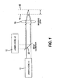
- the invention is described by the schemes shown for the specific case of two laser diodes 10, 12 that emit in two different wavelengths.
- the focus points 18, 20 at the different wavelengths will be shifted one relative to each other.
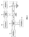
- Figure 2 describes the same idea as Figure 1 for the case of fiber coupled diodes.
- the two different wavelengths are combined into one fiber using a fiber optic coupler 26 instead of the beam combiner 22.
- Polarization beam combiners are well known elements used in the optical field to couple light sources that have different configurations. Polarization beam combiners are available in both free space and fiber (mainly for single mode fibers) coupled configurations.
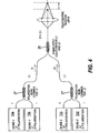
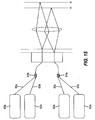
- Figure 4 shows the same general concept as Figure 3 for the case of fiber coupled diodes in an embodiment using two different wavelengths.
- the power of two fiber coupled diodes that emit the same wavelength 10a, 10b is first combined into one fiber by using a polarization fiber-optic combiner 27.
- Two additional diodes 10c, 10d, which emit a second wavelength are combined into one path.
- Figure 6 shows laser diodes 30a, 30b with different wavelengths located adjacent to each other.
- the optical head (not shown) moves along the plate, in the direction indicated by arrow 31.
- laser diode 30b is activated and just then the laser diode 30a, i.e. when it reached the same pixel which was already exposed by laser diode 30b.
- the embodiment described uses fiber coupled diodes. The description is just for two out of n channels. The same general idea can of course be implemented, with no fibers.
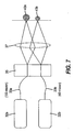
- Optical fibers 33a and 33b with different core diameters can be assembled on the same V-groove 35, as shown in Figure 7 . This can be implemented for the same or different wavelengths. This way, by using only one imaging lens 37 one can get spots of two sizes.
- the figures show an example for two laser diodes 32a and 32b of the same wavelength. If optical fiber 33b is a 40 micron fiber and optical fiber 33a is a 100 micron fiber, then by using a 1x2 imaging lens 37 one gets a 20 micron spot 40b and a 50 micron spot 40a.
- FIG 8 shows the same concept, but now the laser diodes 41 a and 41b emit at different wavelengths. Spots of different diameters 42a and 42b respectively are achieved at different locations.
- Figure 9 shows the distal tips of optical fibers 43a and 43b in different object planes 45 and 46 respectively relative to each other. As a result, the image planes 47 and 48 of the different fiber tips respectively will be shifted one relative to the other.
- Figure 9 shows the effect just for two fibers.
- the optical fibers can be identical, or different, for example with different core diameters. Fibers can emit radiation at the same or different wavelengths.
- the optical radiation guided in the fiber can be in a filled or an underfilled state.
- the laser diodes can be temporally modulated relative to each other in order to get different effects on the direct engraving plate.
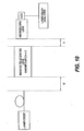
- Figure 10 describes an example of a specific measurement system in which the image position shift was measured.
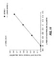
- the graph in Figure 11 shows the relative shift in the image position as a function of the position U, of the distal tip of the fiber, as measured by the system of Figure 10 .
- the shift in image position V was found by moving the position of the microscope lens in order to find the smallest spot.
- a laser beam analyzer was used to measure and define a spot that includes 95% of the laser beam energy.
- moving the distal tip of the fiber in the object plane X mm results in a shift of 0.508 X mm in the image position.
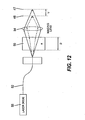
- a glass plate 50 of thickness D placed between the distal tip of the fiber 52 and the imaging lens 54 will cause the image plane to shift from image plane 47 to 48.
- the shift V in the position of the image plane is a function of the thickness D of the plate and its index of refraction n.
- the schematic presents the effect of such a glass plate for the specific case of a single laser diode 55.
- the solid rays describe the case when no plate is used and in which the rays are focused in image plane 47.
- the dashed rays describe the case when a plate is used and in which the focus is shifted to image plane 48.
- the shift V will be a function of the wavelength due to the fact that the index of refraction n, is a function of the wavelength.
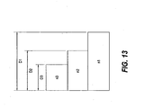
- the glass plate can be constructed from several zones, each having a different thickness and different or same index of refraction as depicted in Figure 13 . Such a structure enables moving and adjusting the glass plate in front of the fiber tips in order to get a required shift.
- the glass plate can also have a variable profile of the index of refraction that changes along the Y direction. This form of the glass plate is shown in Figure 14 . Such a structure enables to move and adjust the right zone of the glass plate in front of the fiber tips in order to get a required shift.
- the glass plate may also be inserted between the imaging lens and the imaged surface.
- Optical detectors 60a and 60b are optically coupled to laser diodes 62a, 62b by fiber optic couplers 61a and 61b and optical fibers 63a through 63d, respectively.
- the laser radiation that impinges on the printing plate is partially reflected backwards and detected by optical detectors 60a and 60b.
- the signal at optical detector 60a, V1, and the signal at optical detector 60b, V2 are proportional to the position of the printing plate. When the plate is in position A the signal at optical detector 60a will be at its maximum value, and when the plate is in position B, the signal at optical detector 60b will be at its maximum value.
- signals V1 and V2 can be used to adjust the imaging lens at a desired distance relative to the position of the printing plate.
- the signals V1 and V2 can be used to inspect and diagnose the printing plate after or during the exposure to the laser beam.
- the Gaussian profile of the beam can be converted, utilizing diffractive optic elements, to be top hat, as depicted in Figure 16
- diffractive optic elements are made by several companies, including: www.holoor.co.il/website/data/index.html.
- the light source described by Figures 1-16 can be a diode laser and/or a fiber coupled diode laser.
- the different configurations in which the fibers are aligned relative to each other described by Figures 1-16 can be done relative to the slow and/or fast axis of the printing drum (the slow and fast axis are well known parameters to any one skilled in the printing art).
- the fibers can be aligned in space in any configuration relative to each other; for example, in a mechanical support, such as a V-groove 65, shown in Figures 17 and 18 .
- the fibers may be aligned one adjacent to the other and/or one above the other, where two or more V-grooves are aligned one on top of the other in a sandwich configuration.
- the specific case of a sandwich configuration can be seen in Figure 17 .
- the diodes can be spatially (by using fibers with different core diameters, or by positioning the distal tips of the fibers at different object planes) and/or temporally modulated relative to each other in order to get different effects on the direct engraving plate. For example, by initiating the first diode before the second diode, etc.
- the multi color light source can be tailored to the special optical and thermal characteristics of a direct engraving printing plate, such as the printing plate described in commonly-assigned copending U.S. Patent Application Serial No. 11/353,217 .
Landscapes
- Physics & Mathematics (AREA)
- Optics & Photonics (AREA)
- Engineering & Computer Science (AREA)
- Plasma & Fusion (AREA)
- Mechanical Engineering (AREA)
- Manufacturing & Machinery (AREA)
- Manufacture Or Reproduction Of Printing Formes (AREA)
- Laser Beam Processing (AREA)
- Optical Couplings Of Light Guides (AREA)
Abstract
Claims (13)
- Système d'impression par gravure directe incluant une tête de formation d'image optique destinée à une gravure directe d'une plaque d'impression flexographique, ladite tête de formation d'image optique comprenant :une première diode laser (10, 10a, 10b, 30a, 41a) émettant un rayonnement dans au moins une première longueur d'onde ; etune deuxième diode laser (12, 10c, 10d, 30b, 41b) émettant un rayonnement à une deuxième longueur d'onde,caractérisé parun moyen destiné à une formation d'image comportant une lentille (16, 37, 54) destinée à former une image desdites première et deuxième longueurs d'onde d'un rayonnement sur une région de la plaque d'impression flexographique ; etoù lesdites première et deuxième longueurs d'onde sont formées en image à différentes profondeurs par rapport à une surface de ladite plaque.
- Tête de formation d'image optique selon la revendication 1, dans laquelle lesdites diodes laser sont couplées à des fibres.
- Tête de formation d'image optique selon la revendication 1 ou 2, dans laquelle ladite lentille comprend une lentille télécentrique.
- Tête de formation d'image optique selon la revendication 1, dans laquelle lesdites diodes laser (10, 12) sont des diodes laser à multiples modes et/ou à mode unique.
- Tête de formation d'image optique selon la revendication 1, dans laquelle lesdites diodes laser sont couplées en utilisant des mélangeurs de faisceaux en fonction d'une longueur d'onde (26).
- Tête de formation d'image optique selon la revendication 1, dans laquelle lesdites diodes laser sont couplées en utilisant des mélangeurs de faisceaux en fonction d'une polarisation (24, 27).
- Tête de formation d'image optique selon la revendication 1, comprenant un moyen destiné à moduler dans le temps de manière directe les lasers l'un par rapport à l'autre.
- Tête de formation d'image optique selon la revendication 1, dans laquelle ledit moyen destiné à une formation d'image comprend une plaque de verre (50) dans le trajet optique.
- Tête de formation d'image optique selon la revendication 1, dans laquelle ledit moyen destiné à une formation d'image comprend des éléments optiques dispersifs.
- Tête de formation d'image optique selon la revendication 1, dans laquelle ladite formation d'image à différentes profondeurs par rapport à ladite surface de plaque est réalisée par l'ajustement desdites diodes ou bien des extrémités distales desdites fibres sont dans des plans objets différents d'une lentille télécentrique.
- Tête de formation d'image optique selon la revendication 1, dans laquelle les éléments optiques diffractifs convertissent un profil gaussien du faisceau en une forme de type chapeau haut-de-forme.
- Tête de formation d'image optique selon la revendication 2, dans laquelle lesdites diodes laser couplées à des fibres sont dotées de diamètres du coeur différents de manière à graver des points de différentes dimensions sur ladite plaque.
- Tête de formation d'image optique selon la revendication 1, comprenant en outre :un moyen destiné à inspecter et à diagnostiquer ladite plaque impression après ou pendant un rayonnement.
Applications Claiming Priority (2)
| Application Number | Priority Date | Filing Date | Title |
|---|---|---|---|
| US11/424,919 US20080018943A1 (en) | 2006-06-19 | 2006-06-19 | Direct engraving of flexographic printing plates |
| PCT/US2007/013146 WO2007149208A2 (fr) | 2006-06-19 | 2007-06-04 | Gravure directe de circuits imprimés flexographiques |
Publications (2)
| Publication Number | Publication Date |
|---|---|
| EP2029361A2 EP2029361A2 (fr) | 2009-03-04 |
| EP2029361B1 true EP2029361B1 (fr) | 2012-08-08 |
Family
ID=38833939
Family Applications (1)
| Application Number | Title | Priority Date | Filing Date |
|---|---|---|---|
| EP07777391A Not-in-force EP2029361B1 (fr) | 2006-06-19 | 2007-06-04 | Gravure directe de circuits imprimés flexographiques |
Country Status (6)
| Country | Link |
|---|---|
| US (1) | US20080018943A1 (fr) |
| EP (1) | EP2029361B1 (fr) |
| JP (1) | JP2009541091A (fr) |
| KR (1) | KR20090021280A (fr) |
| CN (1) | CN101472742B (fr) |
| WO (1) | WO2007149208A2 (fr) |
Families Citing this family (39)
| Publication number | Priority date | Publication date | Assignee | Title |
|---|---|---|---|---|
| US8621996B2 (en) | 2007-08-27 | 2014-01-07 | Eastman Kodak Company | Engraving of printing plates |
| JP5500831B2 (ja) * | 2008-01-25 | 2014-05-21 | 富士フイルム株式会社 | レリーフ印刷版の作製方法及びレーザー彫刻用印刷版原版 |
| JP5121744B2 (ja) * | 2008-03-07 | 2013-01-16 | 富士フイルム株式会社 | 製版装置及び製版方法 |
| JP4911104B2 (ja) * | 2008-04-21 | 2012-04-04 | パルステック工業株式会社 | レーザ加工装置及びレーザ加工方法 |
| JP5078163B2 (ja) * | 2008-12-05 | 2012-11-21 | 富士フイルム株式会社 | マルチビーム露光走査方法及び装置並びに印刷版の製造方法 |
| JP5009275B2 (ja) * | 2008-12-05 | 2012-08-22 | 富士フイルム株式会社 | マルチビーム露光走査方法及び装置並びに印刷版の製造方法 |
| JP5280919B2 (ja) * | 2009-03-31 | 2013-09-04 | 富士フイルム株式会社 | 露光装置および製版装置 |
| US8111275B2 (en) * | 2009-05-15 | 2012-02-07 | Eastman Kodak Company | System for optically adjusting an imaging head |
| JP2011000864A (ja) * | 2009-06-22 | 2011-01-06 | Seiko Epson Corp | 露光ヘッド、画像形成装置 |
| US8284229B2 (en) * | 2009-09-08 | 2012-10-09 | Eastman Kodak Company | Imaging head for 3D imaging |
| US20110236705A1 (en) | 2010-03-29 | 2011-09-29 | Ophira Melamed | Flexographic printing precursors and methods of making |
| US8365662B2 (en) * | 2010-05-17 | 2013-02-05 | Eastman Kodak Company | Direct engraving of flexographic printing plates |
| US20120240802A1 (en) | 2011-03-22 | 2012-09-27 | Landry-Coltrain Christine J | Laser-engraveable flexographic printing precursors |
| US9156299B2 (en) | 2011-06-30 | 2015-10-13 | Eastman Kodak Company | Laser-imageable flexographic printing precursors and methods of imaging |
| US8603725B2 (en) | 2011-07-28 | 2013-12-10 | Eastman Kodak Company | Laser-engraveable compositions and flexographic printing precursors |
| US8613999B2 (en) | 2011-07-28 | 2013-12-24 | Eastman Kodak Company | Laser-engraveable compositions and flexographic printing precursors comprising organic porous particles |
| WO2013019204A1 (fr) * | 2011-08-01 | 2013-02-07 | Ipg Photonics Corporation | Procédé et appareil de traitement de matériaux à structure composite |
| KR101290519B1 (ko) * | 2011-09-07 | 2013-07-26 | 주식회사 이오테크닉스 | 레이저 가공 장치 |
| US20130101834A1 (en) | 2011-10-20 | 2013-04-25 | Dana Barshishat | Laser-imageable flexographic printing precursors and methods of imaging |
| US9156241B2 (en) | 2011-12-12 | 2015-10-13 | Eastman Kodak Company | Laser-imageable flexographic printing precursors and methods of relief imaging |
| US9266316B2 (en) | 2012-01-18 | 2016-02-23 | Eastman Kodak Company | Dual-layer laser-imageable flexographic printing precursors |
| US20130288006A1 (en) | 2012-04-26 | 2013-10-31 | Anna C. Greene | Laser-engraveable elements and method of use |
| US9522523B2 (en) | 2012-04-30 | 2016-12-20 | Eastman Kodak Company | Laser-imageable flexographic printing precursors and methods of imaging |
| KR101435404B1 (ko) * | 2013-03-11 | 2014-09-01 | 주식회사 쿠키혼 | 이중 파장 하이브리드 레이저 가공장치 및 가공방법 |
| US10226837B2 (en) | 2013-03-15 | 2019-03-12 | Nlight, Inc. | Thermal processing with line beams |
| US9413137B2 (en) | 2013-03-15 | 2016-08-09 | Nlight, Inc. | Pulsed line beam device processing systems using laser diodes |
| FR3005878B1 (fr) * | 2013-05-24 | 2016-05-27 | Saint Gobain | Procede d'obtention d'un substrat muni d'un revetement |
| WO2015053757A1 (fr) | 2013-10-09 | 2015-04-16 | Eastman Kodak Company | Éléments pouvant être mis sous forme de motifs et pouvant être gravés au laser directement et utilisations |
| PL3180823T3 (pl) * | 2014-08-13 | 2022-08-08 | Ipg Photonics Corporation | System, sposób i zastosowanie wielowiązkowego lasera światłowodowego |
| JP5965454B2 (ja) * | 2014-10-14 | 2016-08-03 | 株式会社アマダホールディングス | ダイレクトダイオードレーザ加工装置及びこれを用いた板金の加工方法 |
| JP5909537B1 (ja) * | 2014-10-14 | 2016-04-26 | 株式会社アマダホールディングス | ダイレクトダイオードレーザ発振器、ダイレクトダイオードレーザ加工装置及び反射光検出方法 |
| CN107107267B (zh) * | 2014-11-10 | 2020-08-25 | 康宁股份有限公司 | 使用多个焦点来进行对透明制品的激光加工 |
| JP2018515347A (ja) * | 2015-05-26 | 2018-06-14 | アイピージー フォトニクス コーポレーション | マルチビームレーザシステムおよび溶接のための方法 |
| DE112016002585T5 (de) * | 2015-06-10 | 2018-05-24 | Furukawa Electric Co., Ltd. | Pulslaservorrichtung |
| US10466494B2 (en) | 2015-12-18 | 2019-11-05 | Nlight, Inc. | Reverse interleaving for laser line generators |
| MX2018003224A (es) * | 2016-07-29 | 2019-02-07 | Tecoi Corte S L | Sistema de corte laser con doble fibra. |
| CN106964894A (zh) * | 2016-11-03 | 2017-07-21 | 苏州镭明激光科技有限公司 | 一种可变双焦点激光微加工装置 |
| KR102428750B1 (ko) | 2017-10-19 | 2022-08-02 | 사이머 엘엘씨 | 단일의 리소그래피 노광 패스로 복수의 에어리얼 이미지를 형성하는 방법 |
| CN115335238A (zh) * | 2020-03-11 | 2022-11-11 | 旭化成株式会社 | 层叠体和印刷版的制造方法 |
Family Cites Families (21)
| Publication number | Priority date | Publication date | Assignee | Title |
|---|---|---|---|---|
| EP0308512B1 (fr) * | 1987-02-24 | 1994-06-22 | Nippon Steel Corporation | Appareil pour le matage de rouleaux par un faisceau laser a impulsions |
| WO1992007716A1 (fr) * | 1990-11-01 | 1992-05-14 | Landsman Robert M | Presse typographique |
| US5654125A (en) * | 1995-05-01 | 1997-08-05 | E. I. Du Pont De Nemours And Company | Laser apparatus and process of use |
| JP3528364B2 (ja) * | 1995-10-18 | 2004-05-17 | ソニー株式会社 | レーザビーム合成装置及び合成方法並びにレーザ製版装置及びレーザ製版方法 |
| DE19544502C1 (de) * | 1995-11-29 | 1997-05-15 | Baasel Scheel Lasergraphics Gm | Lasergravuranlage |
| DE19710520C1 (de) * | 1997-03-14 | 1998-09-17 | Roland Man Druckmasch | Druckmaschine mit einer Bebilderungsvorrichtung |
| US6159659A (en) * | 1999-04-26 | 2000-12-12 | Creo Srl | Method for processless flexographic printing and flexographic printing plate |
| US6214276B1 (en) * | 1999-05-18 | 2001-04-10 | Creo Srl | Method of forming objects from thermosensitive composition |
| US6433924B1 (en) * | 2000-11-14 | 2002-08-13 | Optical Coating Laboratory, Inc. | Wavelength-selective optical amplifier |
| FR2820681B1 (fr) * | 2001-02-14 | 2003-05-16 | Sagadev | Dispositif de fabrication d'un cliche d'impression pour l'imprimerie |
| DE10109041A1 (de) * | 2001-02-24 | 2002-09-05 | Heidelberger Druckmasch Ag | Verfahren und Mehrstrahl-Abtastvorrichtung zur Ablation von Flexo-Druckplatten durch Lasergravur |
| ATE282527T1 (de) * | 2001-05-25 | 2004-12-15 | Stork Prints Austria Gmbh | Verfahren und vorrichtund zur herstellung einer druckform |
| US6664498B2 (en) * | 2001-12-04 | 2003-12-16 | General Atomics | Method and apparatus for increasing the material removal rate in laser machining |
| US6515801B1 (en) * | 2001-12-21 | 2003-02-04 | Koninklijke Philips Electronics N.V. | Lateral color compensation for projection displays |
| EP1369230A1 (fr) * | 2002-06-05 | 2003-12-10 | Kba-Giori S.A. | Procédé de fabrication d'une plaque gravée |
| AU2003282929A1 (en) * | 2002-10-17 | 2004-05-04 | Iridex Corporation | Laser delivery device incorporating a plurality of laser source optical fibers |
| US6776543B1 (en) * | 2003-02-04 | 2004-08-17 | Hewlett-Packard Development Company, L.P. | Fiber optic print media thickness sensor and method |
| DE10357432A1 (de) * | 2003-12-09 | 2005-07-07 | Heidelberger Druckmaschinen Ag | Verfahren und Vorrichtung zur Bebilderung einer Druckform |
| TWI250910B (en) * | 2004-03-05 | 2006-03-11 | Olympus Corp | Apparatus for laser machining |
| CN1326692C (zh) * | 2004-07-01 | 2007-07-18 | 深圳市光韵达实业有限公司 | 一种镀镍金属印刷模板及其制造方法 |
| US7827912B2 (en) * | 2006-12-22 | 2010-11-09 | Eastman Kodak Company | Hybrid optical head for direct engraving of flexographic printing plates |
-
2006
- 2006-06-19 US US11/424,919 patent/US20080018943A1/en not_active Abandoned
-
2007
- 2007-06-04 EP EP07777391A patent/EP2029361B1/fr not_active Not-in-force
- 2007-06-04 JP JP2009516499A patent/JP2009541091A/ja active Pending
- 2007-06-04 CN CN2007800231451A patent/CN101472742B/zh not_active Expired - Fee Related
- 2007-06-04 WO PCT/US2007/013146 patent/WO2007149208A2/fr not_active Ceased
- 2007-06-04 KR KR1020087030856A patent/KR20090021280A/ko not_active Withdrawn
Also Published As
| Publication number | Publication date |
|---|---|
| KR20090021280A (ko) | 2009-03-02 |
| CN101472742A (zh) | 2009-07-01 |
| WO2007149208A2 (fr) | 2007-12-27 |
| CN101472742B (zh) | 2013-08-21 |
| WO2007149208A3 (fr) | 2008-04-03 |
| US20080018943A1 (en) | 2008-01-24 |
| JP2009541091A (ja) | 2009-11-26 |
| EP2029361A2 (fr) | 2009-03-04 |
Similar Documents
| Publication | Publication Date | Title |
|---|---|---|
| EP2029361B1 (fr) | Gravure directe de circuits imprimés flexographiques | |
| EP2097260B1 (fr) | Gravure directe de plaques d'impression flexographiques | |
| US6803539B2 (en) | System and method of aligning a microfilter in a laser drilling system using a CCD camera | |
| KR100381943B1 (ko) | 재료가공장치 | |
| US20050013328A1 (en) | Laser radiation source | |
| US7885012B2 (en) | Shearing radiation beam for imaging printing media | |
| US20060279794A1 (en) | Printing form processing with fine and coarse engraving tool processing tracks | |
| CN112846487A (zh) | 一种超快激光多焦点大间距并行加工装置及方法 | |
| JP3923483B2 (ja) | レーザイメージング装置 | |
| US6911659B1 (en) | Method and apparatus for fabricating and trimming optical fiber bragg grating devices | |
| CN115041814B (zh) | 一种脆性材料的激光加工装置及加工方法 | |
| US8111275B2 (en) | System for optically adjusting an imaging head | |
| Loeschner et al. | Micromachining of glass with short ns-pulses and highly repetitive fs-laser pulses | |
| NL2029055B1 (en) | Laser-enabled multi-layer ink adhesion onto optical fibers | |
| KR20060088277A (ko) | 광섬유 전송 레이저를 이용한 레이저 가공방법 및 가공장치 | |
| US20230025312A1 (en) | Laser-enabled multi-layer ink adhesion onto optical fibers | |
| US20060279793A1 (en) | Printing form processing with a plurality of engraving tool tracks forming lines | |
| CN101486128B (zh) | 具有电子遮蔽系统的激光装置 | |
| JPH05508123A (ja) | 焦点決めファイバマウント | |
| WO1997046391A1 (fr) | Faisceau de detection de position de balayage |
Legal Events
| Date | Code | Title | Description |
|---|---|---|---|
| PUAI | Public reference made under article 153(3) epc to a published international application that has entered the european phase |
Free format text: ORIGINAL CODE: 0009012 |
|
| 17P | Request for examination filed |
Effective date: 20081201 |
|
| AK | Designated contracting states |
Kind code of ref document: A2 Designated state(s): AT BE BG CH CY CZ DE DK EE ES FI FR GB GR HU IE IS IT LI LT LU LV MC MT NL PL PT RO SE SI SK TR |
|
| AX | Request for extension of the european patent |
Extension state: AL BA HR MK RS |
|
| 17Q | First examination report despatched |
Effective date: 20090409 |
|
| RBV | Designated contracting states (corrected) |
Designated state(s): DE FR GB |
|
| DAX | Request for extension of the european patent (deleted) | ||
| GRAP | Despatch of communication of intention to grant a patent |
Free format text: ORIGINAL CODE: EPIDOSNIGR1 |
|
| GRAS | Grant fee paid |
Free format text: ORIGINAL CODE: EPIDOSNIGR3 |
|
| GRAA | (expected) grant |
Free format text: ORIGINAL CODE: 0009210 |
|
| AK | Designated contracting states |
Kind code of ref document: B1 Designated state(s): DE FR GB |
|
| REG | Reference to a national code |
Ref country code: GB Ref legal event code: FG4D |
|
| REG | Reference to a national code |
Ref country code: DE Ref legal event code: R096 Ref document number: 602007024601 Country of ref document: DE Effective date: 20120927 |
|
| PLBE | No opposition filed within time limit |
Free format text: ORIGINAL CODE: 0009261 |
|
| STAA | Information on the status of an ep patent application or granted ep patent |
Free format text: STATUS: NO OPPOSITION FILED WITHIN TIME LIMIT |
|
| 26N | No opposition filed |
Effective date: 20130510 |
|
| PGFP | Annual fee paid to national office [announced via postgrant information from national office to epo] |
Ref country code: GB Payment date: 20130529 Year of fee payment: 7 |
|
| PGFP | Annual fee paid to national office [announced via postgrant information from national office to epo] |
Ref country code: FR Payment date: 20130618 Year of fee payment: 7 |
|
| REG | Reference to a national code |
Ref country code: DE Ref legal event code: R097 Ref document number: 602007024601 Country of ref document: DE Effective date: 20130510 |
|
| GBPC | Gb: european patent ceased through non-payment of renewal fee |
Effective date: 20140604 |
|
| REG | Reference to a national code |
Ref country code: FR Ref legal event code: ST Effective date: 20150227 |
|
| PG25 | Lapsed in a contracting state [announced via postgrant information from national office to epo] |
Ref country code: GB Free format text: LAPSE BECAUSE OF NON-PAYMENT OF DUE FEES Effective date: 20140604 Ref country code: FR Free format text: LAPSE BECAUSE OF NON-PAYMENT OF DUE FEES Effective date: 20140630 |
|
| PGFP | Annual fee paid to national office [announced via postgrant information from national office to epo] |
Ref country code: DE Payment date: 20150630 Year of fee payment: 9 |
|
| REG | Reference to a national code |
Ref country code: DE Ref legal event code: R119 Ref document number: 602007024601 Country of ref document: DE |
|
| PG25 | Lapsed in a contracting state [announced via postgrant information from national office to epo] |
Ref country code: DE Free format text: LAPSE BECAUSE OF NON-PAYMENT OF DUE FEES Effective date: 20170103 |