EP2030172B1 - Procédé et appareil de rendu de volume utilisant la colorisation pondérée en profondeur - Google Patents
Procédé et appareil de rendu de volume utilisant la colorisation pondérée en profondeur Download PDFInfo
- Publication number
- EP2030172B1 EP2030172B1 EP07736043.6A EP07736043A EP2030172B1 EP 2030172 B1 EP2030172 B1 EP 2030172B1 EP 07736043 A EP07736043 A EP 07736043A EP 2030172 B1 EP2030172 B1 EP 2030172B1
- Authority
- EP
- European Patent Office
- Prior art keywords
- colorization
- depth
- volume rendering
- data
- map
- Prior art date
- Legal status (The legal status is an assumption and is not a legal conclusion. Google has not performed a legal analysis and makes no representation as to the accuracy of the status listed.)
- Active
Links
Images



Classifications
-
- G—PHYSICS
- G06—COMPUTING OR CALCULATING; COUNTING
- G06T—IMAGE DATA PROCESSING OR GENERATION, IN GENERAL
- G06T15/00—Three-dimensional [3D] image rendering
- G06T15/06—Ray-tracing
-
- G—PHYSICS
- G06—COMPUTING OR CALCULATING; COUNTING
- G06T—IMAGE DATA PROCESSING OR GENERATION, IN GENERAL
- G06T15/00—Three-dimensional [3D] image rendering
- G06T15/08—Volume rendering
-
- G—PHYSICS
- G06—COMPUTING OR CALCULATING; COUNTING
- G06T—IMAGE DATA PROCESSING OR GENERATION, IN GENERAL
- G06T2210/00—Indexing scheme for image generation or computer graphics
- G06T2210/41—Medical
Definitions
- the present embodiments relate generally to medical systems and more particularly, to a method and apparatus for volume rendering using depth weighted colorization.
- Levoy developed the concept of Volume Rendering in the late 1980's, which allowed one to create a 3D-like image directly from a 3D object (i.e., a 3D matrix of numbers). Previous methods required the 3D Volume to be first converted into a set of discrete and quantized surfaces (e.g. Marching Cubes algorithm). Levoy adopted an optical physics model of how the eye/retina sees the visual world, where the model describes a method by which a ray cast line (corresponding to a single pixel of the image plane) would intersect the volume in a manner dependent upon the viewer's location with respect to the 3D object being visualized. The value assigned to the pixel would involve a Compositing operation, which would integrate the interpolated samples along the ray cast line. Such a method is typically used for almost all 3D medical imaging applications.
- Such techniques don't work as well when: (a) using standard 2-D monitors and LCD displays; (b) there is a lack of contrast resolution to support a heavily segmented display (e.g., differentiating between translucent and opaque structures); (c) the 3D object is not easily recognizable (e.g. internal anatomical structures); (e) the volume is noisy; or (f) the structure is static.
- US 2005/134582 A1 it is disclosed a technique for visualizing a volume of interest acquired by, e.g., a tomosynthesis imaging system.
- the technique provides for the use of depth-dependent weighting functions in the determination of pixel values in a volume rendering, which can modify an intensity determination for a pixel, either directly or by modifying other contributing functions, such as for determining occlusion effects.
- the volume rendering may then be displayed for review by a technologist or clinician.
- an improved method and system for overcoming the problems in the art is desired.
- an improved method of differentiating the depth of structures when using volume rendering is desired.
- Figure 1 is a two-dimensional (2D) screen view 10 of a three-dimensional (3D) ultrasound image as is known in the art.
- the image comprises a volume rendered image mapped to a sepia colorization Look-Up-Table (LUT), wherein the horizontal axis, generally indicated by reference numeral 12, is representative of a dimension of length, and can be described in units of millimeters or units or horizontal pixels on a display screen.
- the vertical axis, generally indicated by reference numeral 14 is also representative of a dimension of length, and can be described in units of millimeters or units or vertical pixels on a display screen. While the image appears to look three-dimensional, a review of the structures contained therein is not very helpful with respect to determining whether the structures appear close to a viewer (i.e., a view location), or far away.
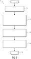
- Figure 2 is a flow diagram view 50 of a method for volume rendering using depth weighted colorization according to one embodiment of the present disclosure.
- the method of volume rendering comprises obtaining data representative of a first composited plane of one or more anatomical structures, generally indicated by reference numeral 52.
- the first composited plane comprises an original composited plane.
- obtaining data comprises obtaining data from a source using one selected from the group consisting of three-dimensional (3D) ultrasound, matrix arrays and real-time 3D imaging.
- the method comprises calculating data of a second composited plane as a function of a first composited plane, wherein the data of the second composited plane is indicative of root-mean square (RMS) depths of the one or more anatomical structures along respective ray cast lines.
- RMS root-mean square
- the method further includes, in step 56, selecting or interpolating color values between two different colorization palettes as a function of the RMS depths of the second composited plane.
- the step includes determining depth weighted color values between two different colorization palettes as a function of the RMS depths of the second composited plane.
- determining comprises one selected from the group consisting of (i) selecting and (ii) interpolating the depth weighted color values between the two different colorization palettes as a function of the RMS depths of the second composited plane.
- determining depth weighted color values between two different colorization palettes as a function of the RMS depths further comprises using a two-dimensional (2D) colorization look-up table (LUT).
- 2D two-dimensional
- determining depth weighted color values between two different colorization palettes as a function of the RMS depths further comprises (i) performing a one-dimensional (1D) look-up table (LUT) operation for each of the two different colorization palettes and (ii) linearly interpolating the results from the 1D LUT operations.
- LUT look-up table
- the method still further includes, in step 58, applying the selected or interpolated color values to the original composited plane for producing a volume rendering with depth weighted colorization.
- the step includes applying the determined depth weighted color values to the first composited plane for producing a volume rendering image with depth weighted colorization.
- applying the determined depth weighted color values comprises applying one selected from the group consisting of the (i) selected color values and (ii) interpolated color values to the first composited plane for producing the volume rendering with depth weighted colorization.
- step 60 further processing according to the particular requirements of a given volume rendering procedure can be performed.
- a compositing method derived from volume rendering techniques includes calculating a second composited plane that is indicative of the RMS depth of the anatomical structure along a ray cast line. This second plane (RMS Depth) is used to select or interpolate between two different colorization palettes that are then applied to an original Levoy composited plane.
- changes in hue are advantageously used to differentiate foreground versus background structures. While changes in hue have been used in Volume Rendering, changes in hue have not been used as a function of depth.
- Classical Volume Rendering often refers to a "classification" stage, where prior to compositing, the quantity at a voxel is converted into an RGB triplet, and then separate compositing occurs for each R, G, and B value. This conversion either depends upon the immediate value of the scalar, or can depend upon a segmented value, which typically is a separate volume used to differentiate between different structures. For example, voxels identified as bone may be encoded using a gray or white palette, whereas voxels from coronaries and arteries would be encoded using a predominantly Red palette.
- i corresponds to the RMS index along the ray cast line (i.e. depth), and which indicates the average index where most of the contribution for the composited sum is obtained.
- Pixel x y RGB _ LUT S i i ⁇ _
- Figure 3 is a two-dimensional (2D) screen view 70 of an example of a depth map for use in the method and system for volume rendering using depth weighted colorization according to an embodiment of the present disclosure.
- Figure 3 contains an alpha map indicating relative depths of structures, wherein the horizontal axis, generally indicated by reference numeral 72, is representative of a dimension of length, and can be described in units of millimeters or units or horizontal pixels on a display screen.
- the vertical axis, generally indicated by reference numeral 74 is also representative of a dimension of length, and can be described in units of millimeters or units or vertical pixels on a display screen.
- the depth map of Figure 3 was obtained using the equations described above, i.e., on image data of Figure 1 , further in which the equations were used to calculate the RMS depth.
- the darker structures are close to the viewer (i.e., view location) and the brighter structures are far away.
- Figure 4 is a 2D screen shot view 80 of an example of a 2D colorization look-up table (LUT) for use in the method and system for volume rendering using depth weighted colorization according to an embodiment of the present disclosure.
- the horizontal axis generally indicated by reference numeral 82, is representative of volume rendered compositing gain, from 0 to approximately just over 250.
- the Summed Composited Value, S N is scaled to this 0 to 250 range (min to max) and this value determines the horizontal index (column) in the 2D colorization LUT. Note how smaller values (closer to 0) correspond to smaller composited values, and thus use RGB values that are darker and have lower luminescence values.
- the vertical axis is representative of a depth of volume structure, from 0 to 100.
- the RMS Depth Value, i is inversely mapped to this 0 to 100 range. As such, small values of i are mapped to values near one-hundred (100), and high values of i are mapped to values near zero (0). A result of this mapping is that structures closer to the viewer (i.e., view location) will result in warmer-redder colors hues, and that structures farther from the viewer (i.e., view location) will be assigned colder-bluer hues.
- selecting or interpolating color values between two different colorization palettes comprises using any standard colorization map (bottom edge), create its complement (top edge), and then linearly interpolate between the standard colorization map and its complement.
- Figure 5 is a 2D screen shot view 90 of an example of a depth colorization volume rendering obtained with the method and system for volume rendering using depth weighted colorization according to one embodiment of the present disclosure.
- screen shot view 90 contains an image blend, wherein the horizontal axis, generally indicated by reference numeral 92, is representative of a dimension of length, and can be described in units of millimeters or units or horizontal pixels on a display screen.
- the vertical axis, generally indicated by reference numeral 94 is also representative of a dimension of length, and can be described in units of millimeters or units or vertical pixels on a display screen.
- the depth colorization volume rendering image of Figure 5 was obtained using the "amplitude" of the composited ray-cast, using the calculated depth map, and performing a 2-dimension look up into the above 2D colorization map of Figure 4 . Accordingly, the depth structures of Figure 5 now "pop", and the depth location is more notable.
- Figure 6 is a 2D screen shot view 100 of an example of a Sobel operator for use in the method and system for volume rendering using depth weighted colorization according to another embodiment of the present disclosure.
- screen shot view 100 contains a Sobel gradient, wherein the horizontal axis, generally indicated by reference numeral 102, is representative of a dimension of length, and can be described in units of millimeters or units or horizontal pixels on a display screen.
- the vertical axis, generally indicated by reference numeral 104 is also representative of a dimension of length, and can be described in units of millimeters or units or vertical pixels on a display screen.
- the method further includes calculating the gradient of the Depth Map of Figure 3 . High gradients occur in locations where the depth changes abruptly and dramatically.
- Figure 7 is a 2D screen shot view 110 of an example of a Sobel modified depth colorization volume rendering obtained with the method and system for volume rendering using depth weighted colorization according to another embodiment of the present disclosure.
- screen shot view 110 contains an image blend with Sobel borders added, wherein the horizontal axis, generally indicated by reference numeral 112, is representative of a dimension of length, and can be described in units of millimeters or units or horizontal pixels on a display screen.
- the vertical axis, generally indicated by reference numeral 114 is representative of a dimension of length, and can be described in units of millimeters or units or vertical pixels on a display screen.
- the Sobel gradient image is used to enhance those portions of the depth colorization volume rendering image where the depth changes dramatically. This is accomplished by using a multiplicative mask operation, where strong gradients are used to darken the red-green-blue colorization (RGB) values.
- RGB red-green-blue colorization
- the method for volume rendering with depth weighted colorization further comprises using a Sobel gradient on the volume rendering image with depth weighted colorization to identify abrupt changes in depth.
- the method includes further enhancing the volume rendering image with depth weighted colorization image as a function of the identified abrupt changes in depth.
- abrupt changes in depth comprise changes in depth can comprise on the order of one hundred percent (100%) between adjacent ray cast lines.
- a method includes application of Sobel detected depth boundaries to a depth weighted colorization image as discussed herein.
- another method includes the application of the Sobel detected depth boundaries to a standard Levoy image (not shown).
- the method for volume rendering with depth weighted colorization further comprises preserving, within the volume rendering image with depth weighted colorization, an average luminance of the first composited plane independent of depth.
- preserving the average luminance includes selecting the two different colorization palettes to comprise a first colorization map and a second colorization map, wherein the second colorization map is the complement of the first colorization map.
- the method can comprise selecting the first colorization map and generating the complement of the first colorization map.
- Generating comprises, for example, converting the first colorization map, in classical RGB space, according to a desired luminance/chrominance transform, wherein converting produces transformed data into a YUV, where the "Y” value corresponds to the luminance, and the "U” and “V” values represent the hue and/or saturation.
- a standard Black- and-White image can be generated simply by using the "Y” value only.
- the complement LUT map involves swapping the two (2) hue signals "U” and “V”, while preserving the luminance signal "Y”. Then an inverse transformation is performed on the YVU signal to generate RGB values for the complement map.
- the method for volume rendering with depth weighted colorization further includes the two different colorization palettes comprising (i) a first colorization map and (ii) a second colorization map, wherein the second colorization map is a complement of the first colorization map.
- the method further includes generating the complement of the first colorization map to acquire the second colorization map.
- generating includes converting the first colorization map according to a desired luminance/chrominance transform, wherein converting produces transformed data; swapping the chrominance components of the transformed data to obtain its complement; and converting the transformed data back to an original space (e.g., RGB) used in the first colorization map.
- an average luminance is preserved independent of depth.
- the desired luminance/chrominance transform comprises a colorization-to-luminance/chrominance (YUV) transform, further wherein swapping the transformed data comprises swapping chrominance (UV) data.
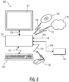
- Figure 8 is a block diagram view of a system for implementing the method of volume rendering using depth weighted colorization according to the embodiments of the present disclosure. That is, the method according to the embodiments of the present disclosure can also be implemented by a clinical workstation or system for implementing a clinical task, as well as be produced in the form of a computer program product. Accordingly, Figure 8 is a partial block diagram view of an apparatus 120 featuring volume rendering with depth weighted colorization according to an embodiment of the present disclosure. Apparatus 120 includes a computer/control unit 122, a display 124, wherein the display 124 is coupled to the computer/control unit 122 via a suitable connection 126.
- Apparatus 120 further includes an input/output device 128 and a pointing device 130, wherein the input/output device 128 and the pointing device 130 are coupled to the computer/control unit 122 via suitable connections 132 and 134, respectively.
- suitable connections can comprise any suitable signal line or lines (wire, wireless, optical, etc.).
- computer/control unit 122 comprises any suitable computer and/or control unit that can be configured for performing the various functionalities as discussed herein with respect to the method for producing a volume rendering image with depth weighted colorization according to the various embodiments.
- programming of the computer/control unit 122, for performing the methods according to the embodiments of the present disclosure as discussed herein, can be accomplished with use of suitable programming techniques.
- computer/control unit 122 interfaces with input/output device 128 (such as a keyboard, audio/voice input device, or similar device), pointing device 130 (such as a mouse, touch screen, or similar device) and display device 124, the computer/control unit for providing imaging data signals to the display for visual display.
- the computer/control unit 122 may further send/receive data from one or more of a mass storage device or media 136 via suitable signal coupling generally indicated by reference numeral 138, and/or a computer network 140 (i.e., for remote data acquisition, storage, analysis, and/or display), etc., via suitable signal coupling generally indicated by reference numeral 42.
- the computer/control unit 122 may further receive data from one or more acquisition device and/or system (not shown), in addition to sending data to one or more device and/or system (not shown), via signal line 144.
- Signal line 144 can comprise any suitable signal line or lines (wire, wireless, optical, etc.).
- system 120 may include a printer device 146 coupled to computer/control unit 122 for suitable use, as may be desired, during a particular procedure involving use of apparatus 120.
- a volume rendering apparatus comprises a display; a computer/control unit coupled to the display, wherein the computer/control unit provides data to the display for rendering a projection view; and an input device coupled to the computer/control unit for providing inputs to the computer/control unit, wherein the computer control unit is programmed with instructions for carrying out the method for producing a volume rendering image with depth weighted colorization as discussed herein.
- a computer program product comprises computer readable media having a set of instructions that are executable by a computer for carrying out the method for producing a volume rendering image with depth weighted colorization as discussed herein.
- any reference signs placed in parentheses in one or more claims shall not be construed as limiting the claims.
- the word “comprising” and “comprises,” and the like, does not exclude the presence of elements or steps other than those listed in any claim or the specification as a whole.
- the singular reference of an element does not exclude the plural references of such elements and vice-versa.
- One or more of the embodiments may be implemented by means of hardware comprising several distinct elements, and/or by means of a suitably programmed computer. In a device claim enumerating several means, several of these means may be embodied by one and the same item of hardware.
- the mere fact that certain measures are recited in mutually different dependent claims does not indicate that a combination of these measures cannot be used to an advantage.
Landscapes
- Engineering & Computer Science (AREA)
- Computer Graphics (AREA)
- Physics & Mathematics (AREA)
- General Physics & Mathematics (AREA)
- Theoretical Computer Science (AREA)
- Image Generation (AREA)
- Image Processing (AREA)
- Apparatus For Radiation Diagnosis (AREA)
- Ultra Sonic Daignosis Equipment (AREA)
- Image Analysis (AREA)
Claims (12)
- Procédé mis en oeuvre sur ordinateur de rendu de volume comprenant :(a) l'obtention de données représentatives d'un premier plan composite d'une ou plusieurs structures opaques le long de lignes de lancer de rayons ;(b) le calcul de données d'un second plan composite en déterminant une seule mesure de profondeur de l'une ou plusieurs structures opaques le long de chaque ligne de lancer de rayons depuis un emplacement de vue du premier plan composite ;(c) la détermination de données de valeur de couleur entre deux palettes de colorisation différentes comme une fonction de la mesure de profondeur de l'une ou plusieurs structures opaques le long des lignes de lancer de rayons ; et(d) l'application des données du second plan composite au premier plan composite pour générer une image de rendu de volume, dans laquelle l'application des données du second plan composite inclut l'application des données de valeur de couleur pour générer l'image de rendu de volume avec une colorisation dépendant de la profondeur.
- Procédé selon la revendication 1, dans lequel le calcul de données du second plan composite inclut la détermination d'une mesure de profondeur moyenne de l'une ou plusieurs structures opaques le long des lignes de lancer de rayons depuis l'emplacement de vue, la mesure de profondeur moyenne étant une profondeur moyenne quadratique.
- Procédé selon la revendication 1 ou 2, dans lequel l'une ou plusieurs structures opaques le long des lignes de lancer de rayons comprennent un ou plusieurs voxels d'un objet tridimensionnel.
- Procédé selon l'une quelconque des revendications 1 à 3, comprenant en outre :
la génération d'une image à partir des données du second plan composite. - Procédé selon la revendication 4, comprenant en outre :
l'identification, dans l'image produite à partir des données du second plan composite, d'au moins une ou plusieurs limites ou bordures entre des structures ayant des profondeurs différentes depuis l'emplacement de vue, dans laquelle l'identification inclut l'utilisation d'un opérateur de gradient bidimensionnel. - Procédé selon la revendication 5, dans lequel l'opérateur de gradient bidimensionnel est un filtre de Sobel.
- Procédé selon la revendication 5 ou 6, comprenant en outre :
l'amélioration de l'image de rendu de volume avec une colorisation pondérée en profondeur sur la base de l'une ou plusieurs limites ou bordures identifiées entre des structures ayant des profondeurs différentes depuis l'emplacement de vue. - Procédé selon l'une quelconque des revendications 1 à 7, dans lequel la détermination des données de valeur de couleur inclut l'utilisation d'un graphique de table de correspondance (LUT) de colorisation bidimensionnel (2D).
- Procédé selon la revendication 8, dans lequel en outre le graphique de LUT de colorisation 2D est généré en sélectionnant un graphique de colorisation unidimensionnel, en générant son complément, et en interpolant entre le graphique de colorisation unidimensionnel et son complément.
- Procédé selon la revendication 9, dans lequel en outre le graphique de colorisation unidimensionnel comprend une transformation colorisation-luminance/chrominance (YUV), et dans lequel la génération de son complément comprend la transformation de YUV en YVU.
- Appareil comprenant :un écran ;une unité de commande couplée à l'écran, dans laquelle l'unité de commande fournit des données à l'écran pour rendre une vue d'écran ; etun moyen couplé à l'unité de commande pour fournir des entrées à l'unité de commande, dans lequel l'unité de commande est programmée avec des instructions, réactives audit moyen d'entrée, pour exécuter le procédé mis en oeuvre sur ordinateur de rendu de volume selon l'une quelconque des revendications 1 à 10.
- Produit de programme pour ordinateur comprenant :
des supports lisibles sur ordinateur possédant un ensemble d'instructions qui sont exécutables par un ordinateur pour exécuter le procédé mis en oeuvre sur ordinateur de rendu de volume selon l'une quelconque des revendications 1 à 10.
Applications Claiming Priority (2)
| Application Number | Priority Date | Filing Date | Title |
|---|---|---|---|
| US80351406P | 2006-05-31 | 2006-05-31 | |
| PCT/IB2007/052021 WO2007138551A2 (fr) | 2006-05-31 | 2007-05-29 | Procédé et appareil de rendu de volume utilisant la colorisation pondérée en profondeur |
Publications (2)
| Publication Number | Publication Date |
|---|---|
| EP2030172A2 EP2030172A2 (fr) | 2009-03-04 |
| EP2030172B1 true EP2030172B1 (fr) | 2019-07-31 |
Family
ID=38544163
Family Applications (1)
| Application Number | Title | Priority Date | Filing Date |
|---|---|---|---|
| EP07736043.6A Active EP2030172B1 (fr) | 2006-05-31 | 2007-05-29 | Procédé et appareil de rendu de volume utilisant la colorisation pondérée en profondeur |
Country Status (6)
| Country | Link |
|---|---|
| US (1) | US8477135B2 (fr) |
| EP (1) | EP2030172B1 (fr) |
| JP (1) | JP5117490B2 (fr) |
| KR (1) | KR101345362B1 (fr) |
| CN (1) | CN101454806B (fr) |
| WO (1) | WO2007138551A2 (fr) |
Families Citing this family (15)
| Publication number | Priority date | Publication date | Assignee | Title |
|---|---|---|---|---|
| CN101860655B (zh) * | 2010-07-02 | 2012-04-25 | 上海交通大学 | 基于双边滤波器的黑白图像彩色化方法 |
| WO2012056354A2 (fr) * | 2010-10-25 | 2012-05-03 | Koninklijke Philips Electronics N.V. | Visualisation de volume |
| US8861836B2 (en) * | 2011-01-14 | 2014-10-14 | Sony Corporation | Methods and systems for 2D to 3D conversion from a portrait image |
| CN102096939B (zh) * | 2011-02-25 | 2013-06-05 | 浙江工业大学 | 面向医学海量数据的多分辨率体绘制方法 |
| US20130150719A1 (en) * | 2011-12-08 | 2013-06-13 | General Electric Company | Ultrasound imaging system and method |
| KR20140093364A (ko) | 2013-01-16 | 2014-07-28 | 삼성전자주식회사 | 의료 영상 생성 장치 및 방법 |
| JP6427486B2 (ja) * | 2013-04-12 | 2018-11-21 | 株式会社日立製作所 | 超音波診断装置及び超音波三次元画像作成方法 |
| KR102111626B1 (ko) * | 2013-09-10 | 2020-05-15 | 삼성전자주식회사 | 영상 처리 장치 및 영상 처리 방법 |
| CN104143203B (zh) * | 2014-07-29 | 2017-02-15 | 清华大学深圳研究生院 | 一种图像编辑传播方法 |
| WO2016177788A1 (fr) | 2015-05-04 | 2016-11-10 | Koninklijke Philips N.V. | Dispositif de visualisation de profondeur d'un objet prédéfini |
| WO2017165566A1 (fr) * | 2016-03-25 | 2017-09-28 | The Regents Of The University Of California | Images, animations et vidéos en couleurs à haute définition pour des applications d'imagerie personnelle et de diagnostic |
| CN106530383B (zh) * | 2016-11-01 | 2017-08-22 | 河海大学 | 基于Hermite插值神经网络回归模型的人脸面部渲染方法 |
| US10489969B2 (en) * | 2017-11-08 | 2019-11-26 | General Electric Company | Method and system for presenting shaded descriptors corresponding with shaded ultrasound images |
| KR102446033B1 (ko) * | 2017-11-13 | 2022-09-23 | 삼성디스플레이 주식회사 | 색역 변환 방법 및 이를 채용한 표시 장치 |
| CN116309899A (zh) * | 2022-12-05 | 2023-06-23 | 深圳英美达医疗技术有限公司 | 三维成像方法、系统、电子设备和可读存储介质 |
Family Cites Families (17)
| Publication number | Priority date | Publication date | Assignee | Title |
|---|---|---|---|---|
| US4596145A (en) * | 1983-09-20 | 1986-06-24 | Smith Stephen W | Acoustic orthoscopic imaging system |
| US6177923B1 (en) * | 1994-12-30 | 2001-01-23 | Acuson Corporation | Imaging modality showing energy and velocity |
| JP3570576B2 (ja) * | 1995-06-19 | 2004-09-29 | 株式会社日立製作所 | マルチモダリティに対応した3次元画像合成表示装置 |
| EP1001375A3 (fr) * | 1998-11-12 | 2002-01-09 | TeraRecon, Inc., A Delaware Corporation | Recadrage avec pipeline pour manipuler des ensembles de données de volume en temps réel |
| US6868191B2 (en) * | 2000-06-28 | 2005-03-15 | Telefonaktiebolaget Lm Ericsson (Publ) | System and method for median fusion of depth maps |
| WO2002063569A1 (fr) * | 2001-02-09 | 2002-08-15 | Koninklijke Philips Electronics N.V. | Procede permettant de rendre un volume |
| JP2003110869A (ja) * | 2001-03-12 | 2003-04-11 | Sharp Corp | 画像処理装置、画像形成装置、画像処理方法、プログラム、および記録媒体 |
| JP3499541B2 (ja) * | 2001-07-25 | 2004-02-23 | ザイオソフト株式会社 | 3次元画像表示方法、装置およびプログラム |
| US7372470B2 (en) * | 2001-11-29 | 2008-05-13 | Lg Electronics Inc. | System and method for transmitting and displaying messages in a mobile terminal |
| US7203356B2 (en) * | 2002-04-11 | 2007-04-10 | Canesta, Inc. | Subject segmentation and tracking using 3D sensing technology for video compression in multimedia applications |
| DE10253617B4 (de) * | 2002-11-15 | 2005-06-30 | Siemens Ag | Verfahren zur Darstellung eines ineinem Volumendatensatz abgebildeten Objektes |
| JP3836097B2 (ja) * | 2003-09-19 | 2006-10-18 | ザイオソフト株式会社 | 医用画像生成装置および方法、ならびに、プログラム |
| KR100546383B1 (ko) * | 2003-09-29 | 2006-01-26 | 삼성전자주식회사 | 눈에 보이지 않는 프래그먼트를 처리하기 위한 3차원그래픽스 렌더링 엔진 및 그 방법 |
| US20050110793A1 (en) * | 2003-11-21 | 2005-05-26 | Steen Erik N. | Methods and systems for graphics processing in a medical imaging system |
| US7250949B2 (en) * | 2003-12-23 | 2007-07-31 | General Electric Company | Method and system for visualizing three-dimensional data |
| TWI247220B (en) * | 2004-01-16 | 2006-01-11 | Via Tech Inc | 3D image processing method |
| US7154500B2 (en) * | 2004-04-20 | 2006-12-26 | The Chinese University Of Hong Kong | Block-based fragment filtration with feasible multi-GPU acceleration for real-time volume rendering on conventional personal computer |
-
2007
- 2007-05-29 JP JP2009512744A patent/JP5117490B2/ja active Active
- 2007-05-29 EP EP07736043.6A patent/EP2030172B1/fr active Active
- 2007-05-29 CN CN200780019684.8A patent/CN101454806B/zh active Active
- 2007-05-29 WO PCT/IB2007/052021 patent/WO2007138551A2/fr not_active Ceased
- 2007-05-29 US US12/302,946 patent/US8477135B2/en active Active
- 2007-05-29 KR KR1020087029096A patent/KR101345362B1/ko not_active Expired - Fee Related
Non-Patent Citations (1)
| Title |
|---|
| None * |
Also Published As
| Publication number | Publication date |
|---|---|
| JP2009539164A (ja) | 2009-11-12 |
| US20090184955A1 (en) | 2009-07-23 |
| WO2007138551A2 (fr) | 2007-12-06 |
| US8477135B2 (en) | 2013-07-02 |
| EP2030172A2 (fr) | 2009-03-04 |
| KR101345362B1 (ko) | 2013-12-30 |
| JP5117490B2 (ja) | 2013-01-16 |
| WO2007138551A3 (fr) | 2008-06-05 |
| CN101454806A (zh) | 2009-06-10 |
| KR20090014180A (ko) | 2009-02-06 |
| CN101454806B (zh) | 2014-01-29 |
Similar Documents
| Publication | Publication Date | Title |
|---|---|---|
| EP2030172B1 (fr) | Procédé et appareil de rendu de volume utilisant la colorisation pondérée en profondeur | |
| CN111508052B (zh) | 三维网格体的渲染方法和装置 | |
| DE69328464T2 (de) | Methode zur Berechnung der Beleuchtung für Daten dreidimensionaler Objekte | |
| US7912264B2 (en) | Multi-volume rendering of single mode data in medical diagnostic imaging | |
| US4835712A (en) | Methods and apparatus for imaging volume data with shading | |
| CN101601287B (zh) | 产生照片级真实感图像缩略图的设备和方法 | |
| DE69331486T2 (de) | Bilddatenverarbeitung | |
| JPH0727576B2 (ja) | 三次元デ−タセツトを表す二次元デ−タ表示を発生する方法 | |
| DE102005035012A1 (de) | Hochleistungsschattierung von großen volumetrischen Daten unter Verwendung von partiellen Schirmraumableitungen | |
| US8184119B2 (en) | Fast ambient occlusion for direct volume rendering | |
| US5068808A (en) | Imager and process | |
| US6967653B2 (en) | Apparatus and method for semi-automatic classification of volume data | |
| US5379370A (en) | Method and apparatus for drawing lines, curves, and points coincident with a surface | |
| US6766281B1 (en) | Matched texture filter design for rendering multi-rate data samples | |
| US5159663A (en) | Imager and process | |
| Rezk-Salama et al. | Automatic Adjustment of Transfer Functions for 3D Volume Visualization. | |
| AU2019298637B2 (en) | Method and device for displaying high-dynamic sonar or radar data | |
| EP3195251B1 (fr) | Procédé pour améliorer le contraste à artefacts visuels réduits | |
| EP1001375A2 (fr) | Recadrage avec pipeline pour manipuler des ensembles de données de volume en temps réel | |
| US6295369B1 (en) | Multi-dimensional color image mapping apparatus and method | |
| CN118735979B (zh) | 一种用于艺术作品的虚拟图像生成方法及系统 | |
| Shiraishi et al. | Adaptive parameter control for image moment-based painterly rendering | |
| KR970049862A (ko) | 화상 처리를 이용한 화상 생성 장치 및 그 방법 | |
| US20080310708A1 (en) | Method for Improving Image Viewing Properties of an Image | |
| Zhou et al. | Control of object visibility in volume rendering—a distance-based approach |
Legal Events
| Date | Code | Title | Description |
|---|---|---|---|
| PUAI | Public reference made under article 153(3) epc to a published international application that has entered the european phase |
Free format text: ORIGINAL CODE: 0009012 |
|
| 17P | Request for examination filed |
Effective date: 20090105 |
|
| AK | Designated contracting states |
Kind code of ref document: A2 Designated state(s): AT BE BG CH CY CZ DE DK EE ES FI FR GB GR HU IE IS IT LI LT LU LV MC MT NL PL PT RO SE SI SK TR |
|
| AX | Request for extension of the european patent |
Extension state: AL BA HR MK RS |
|
| 17Q | First examination report despatched |
Effective date: 20090605 |
|
| DAX | Request for extension of the european patent (deleted) | ||
| RAP1 | Party data changed (applicant data changed or rights of an application transferred) |
Owner name: KONINKLIJKE PHILIPS N.V. |
|
| STAA | Information on the status of an ep patent application or granted ep patent |
Free format text: STATUS: EXAMINATION IS IN PROGRESS |
|
| REG | Reference to a national code |
Ref country code: DE Ref legal event code: R079 Ref document number: 602007058934 Country of ref document: DE Free format text: PREVIOUS MAIN CLASS: G06T0015500000 Ipc: G06T0015060000 |
|
| GRAP | Despatch of communication of intention to grant a patent |
Free format text: ORIGINAL CODE: EPIDOSNIGR1 |
|
| STAA | Information on the status of an ep patent application or granted ep patent |
Free format text: STATUS: GRANT OF PATENT IS INTENDED |
|
| RIC1 | Information provided on ipc code assigned before grant |
Ipc: G06T 15/06 20110101AFI20190130BHEP Ipc: G06T 15/08 20110101ALI20190130BHEP |
|
| INTG | Intention to grant announced |
Effective date: 20190225 |
|
| GRAS | Grant fee paid |
Free format text: ORIGINAL CODE: EPIDOSNIGR3 |
|
| GRAA | (expected) grant |
Free format text: ORIGINAL CODE: 0009210 |
|
| STAA | Information on the status of an ep patent application or granted ep patent |
Free format text: STATUS: THE PATENT HAS BEEN GRANTED |
|
| AK | Designated contracting states |
Kind code of ref document: B1 Designated state(s): AT BE BG CH CY CZ DE DK EE ES FI FR GB GR HU IE IS IT LI LT LU LV MC MT NL PL PT RO SE SI SK TR |
|
| REG | Reference to a national code |
Ref country code: CH Ref legal event code: EP Ref country code: GB Ref legal event code: FG4D |
|
| REG | Reference to a national code |
Ref country code: AT Ref legal event code: REF Ref document number: 1161724 Country of ref document: AT Kind code of ref document: T Effective date: 20190815 |
|
| REG | Reference to a national code |
Ref country code: IE Ref legal event code: FG4D |
|
| REG | Reference to a national code |
Ref country code: DE Ref legal event code: R096 Ref document number: 602007058934 Country of ref document: DE |
|
| REG | Reference to a national code |
Ref country code: DE Ref legal event code: R084 Ref document number: 602007058934 Country of ref document: DE |
|
| REG | Reference to a national code |
Ref country code: GB Ref legal event code: 746 Effective date: 20190821 |
|
| REG | Reference to a national code |
Ref country code: NL Ref legal event code: MP Effective date: 20190731 |
|
| REG | Reference to a national code |
Ref country code: LT Ref legal event code: MG4D |
|
| REG | Reference to a national code |
Ref country code: AT Ref legal event code: MK05 Ref document number: 1161724 Country of ref document: AT Kind code of ref document: T Effective date: 20190731 |
|
| PG25 | Lapsed in a contracting state [announced via postgrant information from national office to epo] |
Ref country code: SE Free format text: LAPSE BECAUSE OF FAILURE TO SUBMIT A TRANSLATION OF THE DESCRIPTION OR TO PAY THE FEE WITHIN THE PRESCRIBED TIME-LIMIT Effective date: 20190731 Ref country code: BG Free format text: LAPSE BECAUSE OF FAILURE TO SUBMIT A TRANSLATION OF THE DESCRIPTION OR TO PAY THE FEE WITHIN THE PRESCRIBED TIME-LIMIT Effective date: 20191031 Ref country code: PT Free format text: LAPSE BECAUSE OF FAILURE TO SUBMIT A TRANSLATION OF THE DESCRIPTION OR TO PAY THE FEE WITHIN THE PRESCRIBED TIME-LIMIT Effective date: 20191202 Ref country code: NL Free format text: LAPSE BECAUSE OF FAILURE TO SUBMIT A TRANSLATION OF THE DESCRIPTION OR TO PAY THE FEE WITHIN THE PRESCRIBED TIME-LIMIT Effective date: 20190731 Ref country code: LT Free format text: LAPSE BECAUSE OF FAILURE TO SUBMIT A TRANSLATION OF THE DESCRIPTION OR TO PAY THE FEE WITHIN THE PRESCRIBED TIME-LIMIT Effective date: 20190731 Ref country code: FI Free format text: LAPSE BECAUSE OF FAILURE TO SUBMIT A TRANSLATION OF THE DESCRIPTION OR TO PAY THE FEE WITHIN THE PRESCRIBED TIME-LIMIT Effective date: 20190731 Ref country code: AT Free format text: LAPSE BECAUSE OF FAILURE TO SUBMIT A TRANSLATION OF THE DESCRIPTION OR TO PAY THE FEE WITHIN THE PRESCRIBED TIME-LIMIT Effective date: 20190731 |
|
| PG25 | Lapsed in a contracting state [announced via postgrant information from national office to epo] |
Ref country code: ES Free format text: LAPSE BECAUSE OF FAILURE TO SUBMIT A TRANSLATION OF THE DESCRIPTION OR TO PAY THE FEE WITHIN THE PRESCRIBED TIME-LIMIT Effective date: 20190731 Ref country code: GR Free format text: LAPSE BECAUSE OF FAILURE TO SUBMIT A TRANSLATION OF THE DESCRIPTION OR TO PAY THE FEE WITHIN THE PRESCRIBED TIME-LIMIT Effective date: 20191101 Ref country code: IS Free format text: LAPSE BECAUSE OF FAILURE TO SUBMIT A TRANSLATION OF THE DESCRIPTION OR TO PAY THE FEE WITHIN THE PRESCRIBED TIME-LIMIT Effective date: 20191130 Ref country code: LV Free format text: LAPSE BECAUSE OF FAILURE TO SUBMIT A TRANSLATION OF THE DESCRIPTION OR TO PAY THE FEE WITHIN THE PRESCRIBED TIME-LIMIT Effective date: 20190731 |
|
| RAP2 | Party data changed (patent owner data changed or rights of a patent transferred) |
Owner name: KONINKLIJKE PHILIPS N.V. |
|
| PG25 | Lapsed in a contracting state [announced via postgrant information from national office to epo] |
Ref country code: TR Free format text: LAPSE BECAUSE OF FAILURE TO SUBMIT A TRANSLATION OF THE DESCRIPTION OR TO PAY THE FEE WITHIN THE PRESCRIBED TIME-LIMIT Effective date: 20190731 |
|
| PG25 | Lapsed in a contracting state [announced via postgrant information from national office to epo] |
Ref country code: IT Free format text: LAPSE BECAUSE OF FAILURE TO SUBMIT A TRANSLATION OF THE DESCRIPTION OR TO PAY THE FEE WITHIN THE PRESCRIBED TIME-LIMIT Effective date: 20190731 Ref country code: RO Free format text: LAPSE BECAUSE OF FAILURE TO SUBMIT A TRANSLATION OF THE DESCRIPTION OR TO PAY THE FEE WITHIN THE PRESCRIBED TIME-LIMIT Effective date: 20190731 Ref country code: EE Free format text: LAPSE BECAUSE OF FAILURE TO SUBMIT A TRANSLATION OF THE DESCRIPTION OR TO PAY THE FEE WITHIN THE PRESCRIBED TIME-LIMIT Effective date: 20190731 Ref country code: PL Free format text: LAPSE BECAUSE OF FAILURE TO SUBMIT A TRANSLATION OF THE DESCRIPTION OR TO PAY THE FEE WITHIN THE PRESCRIBED TIME-LIMIT Effective date: 20190731 Ref country code: DK Free format text: LAPSE BECAUSE OF FAILURE TO SUBMIT A TRANSLATION OF THE DESCRIPTION OR TO PAY THE FEE WITHIN THE PRESCRIBED TIME-LIMIT Effective date: 20190731 |
|
| PG25 | Lapsed in a contracting state [announced via postgrant information from national office to epo] |
Ref country code: IS Free format text: LAPSE BECAUSE OF FAILURE TO SUBMIT A TRANSLATION OF THE DESCRIPTION OR TO PAY THE FEE WITHIN THE PRESCRIBED TIME-LIMIT Effective date: 20200224 Ref country code: SK Free format text: LAPSE BECAUSE OF FAILURE TO SUBMIT A TRANSLATION OF THE DESCRIPTION OR TO PAY THE FEE WITHIN THE PRESCRIBED TIME-LIMIT Effective date: 20190731 Ref country code: CZ Free format text: LAPSE BECAUSE OF FAILURE TO SUBMIT A TRANSLATION OF THE DESCRIPTION OR TO PAY THE FEE WITHIN THE PRESCRIBED TIME-LIMIT Effective date: 20190731 |
|
| REG | Reference to a national code |
Ref country code: DE Ref legal event code: R097 Ref document number: 602007058934 Country of ref document: DE |
|
| PLBE | No opposition filed within time limit |
Free format text: ORIGINAL CODE: 0009261 |
|
| STAA | Information on the status of an ep patent application or granted ep patent |
Free format text: STATUS: NO OPPOSITION FILED WITHIN TIME LIMIT |
|
| PG2D | Information on lapse in contracting state deleted |
Ref country code: IS |
|
| PG25 | Lapsed in a contracting state [announced via postgrant information from national office to epo] |
Ref country code: IS Free format text: LAPSE BECAUSE OF FAILURE TO SUBMIT A TRANSLATION OF THE DESCRIPTION OR TO PAY THE FEE WITHIN THE PRESCRIBED TIME-LIMIT Effective date: 20191030 |
|
| 26N | No opposition filed |
Effective date: 20200603 |
|
| PG25 | Lapsed in a contracting state [announced via postgrant information from national office to epo] |
Ref country code: SI Free format text: LAPSE BECAUSE OF FAILURE TO SUBMIT A TRANSLATION OF THE DESCRIPTION OR TO PAY THE FEE WITHIN THE PRESCRIBED TIME-LIMIT Effective date: 20190731 |
|
| PG25 | Lapsed in a contracting state [announced via postgrant information from national office to epo] |
Ref country code: LI Free format text: LAPSE BECAUSE OF NON-PAYMENT OF DUE FEES Effective date: 20200531 Ref country code: CH Free format text: LAPSE BECAUSE OF NON-PAYMENT OF DUE FEES Effective date: 20200531 Ref country code: MC Free format text: LAPSE BECAUSE OF FAILURE TO SUBMIT A TRANSLATION OF THE DESCRIPTION OR TO PAY THE FEE WITHIN THE PRESCRIBED TIME-LIMIT Effective date: 20190731 |
|
| REG | Reference to a national code |
Ref country code: BE Ref legal event code: MM Effective date: 20200531 |
|
| PG25 | Lapsed in a contracting state [announced via postgrant information from national office to epo] |
Ref country code: LU Free format text: LAPSE BECAUSE OF NON-PAYMENT OF DUE FEES Effective date: 20200529 |
|
| PG25 | Lapsed in a contracting state [announced via postgrant information from national office to epo] |
Ref country code: IE Free format text: LAPSE BECAUSE OF NON-PAYMENT OF DUE FEES Effective date: 20200529 |
|
| PG25 | Lapsed in a contracting state [announced via postgrant information from national office to epo] |
Ref country code: BE Free format text: LAPSE BECAUSE OF NON-PAYMENT OF DUE FEES Effective date: 20200531 |
|
| PG25 | Lapsed in a contracting state [announced via postgrant information from national office to epo] |
Ref country code: MT Free format text: LAPSE BECAUSE OF FAILURE TO SUBMIT A TRANSLATION OF THE DESCRIPTION OR TO PAY THE FEE WITHIN THE PRESCRIBED TIME-LIMIT Effective date: 20190731 Ref country code: CY Free format text: LAPSE BECAUSE OF FAILURE TO SUBMIT A TRANSLATION OF THE DESCRIPTION OR TO PAY THE FEE WITHIN THE PRESCRIBED TIME-LIMIT Effective date: 20190731 |
|
| PGFP | Annual fee paid to national office [announced via postgrant information from national office to epo] |
Ref country code: FR Payment date: 20230523 Year of fee payment: 17 |
|
| PG25 | Lapsed in a contracting state [announced via postgrant information from national office to epo] |
Ref country code: FR Free format text: LAPSE BECAUSE OF NON-PAYMENT OF DUE FEES Effective date: 20240531 |
|
| PGFP | Annual fee paid to national office [announced via postgrant information from national office to epo] |
Ref country code: DE Payment date: 20250528 Year of fee payment: 19 |
|
| PGFP | Annual fee paid to national office [announced via postgrant information from national office to epo] |
Ref country code: GB Payment date: 20260304 Year of fee payment: 20 |