EP2030497A2 - Contrôles de direction à double levier avec arrêts de contrôles - Google Patents
Contrôles de direction à double levier avec arrêts de contrôles Download PDFInfo
- Publication number
- EP2030497A2 EP2030497A2 EP08162279A EP08162279A EP2030497A2 EP 2030497 A2 EP2030497 A2 EP 2030497A2 EP 08162279 A EP08162279 A EP 08162279A EP 08162279 A EP08162279 A EP 08162279A EP 2030497 A2 EP2030497 A2 EP 2030497A2
- Authority
- EP
- European Patent Office
- Prior art keywords
- control
- lever
- stop
- steering controls
- dual
- Prior art date
- Legal status (The legal status is an assumption and is not a legal conclusion. Google has not performed a legal analysis and makes no representation as to the accuracy of the status listed.)
- Granted
Links
Images

Classifications
-
- A—HUMAN NECESSITIES
- A01—AGRICULTURE; FORESTRY; ANIMAL HUSBANDRY; HUNTING; TRAPPING; FISHING
- A01D—HARVESTING; MOWING
- A01D34/00—Mowers; Mowing apparatus of harvesters
- A01D34/01—Mowers; Mowing apparatus of harvesters characterised by features relating to the type of cutting apparatus
- A01D34/412—Mowers; Mowing apparatus of harvesters characterised by features relating to the type of cutting apparatus having rotating cutters
- A01D34/63—Mowers; Mowing apparatus of harvesters characterised by features relating to the type of cutting apparatus having rotating cutters having cutters rotating about a vertical axis
- A01D34/67—Mowers; Mowing apparatus of harvesters characterised by features relating to the type of cutting apparatus having rotating cutters having cutters rotating about a vertical axis hand-guided by a walking operator
- A01D34/68—Mowers; Mowing apparatus of harvesters characterised by features relating to the type of cutting apparatus having rotating cutters having cutters rotating about a vertical axis hand-guided by a walking operator with motor driven cutters or wheels
- A01D34/69—Mowers; Mowing apparatus of harvesters characterised by features relating to the type of cutting apparatus having rotating cutters having cutters rotating about a vertical axis hand-guided by a walking operator with motor driven cutters or wheels with motor driven wheels
-
- A—HUMAN NECESSITIES
- A01—AGRICULTURE; FORESTRY; ANIMAL HUSBANDRY; HUNTING; TRAPPING; FISHING
- A01D—HARVESTING; MOWING
- A01D34/00—Mowers; Mowing apparatus of harvesters
- A01D34/01—Mowers; Mowing apparatus of harvesters characterised by features relating to the type of cutting apparatus
- A01D34/412—Mowers; Mowing apparatus of harvesters characterised by features relating to the type of cutting apparatus having rotating cutters
- A01D34/63—Mowers; Mowing apparatus of harvesters characterised by features relating to the type of cutting apparatus having rotating cutters having cutters rotating about a vertical axis
- A01D34/64—Mowers; Mowing apparatus of harvesters characterised by features relating to the type of cutting apparatus having rotating cutters having cutters rotating about a vertical axis mounted on a vehicle, e.g. a tractor, or drawn by an animal or a vehicle
-
- A—HUMAN NECESSITIES
- A01—AGRICULTURE; FORESTRY; ANIMAL HUSBANDRY; HUNTING; TRAPPING; FISHING
- A01D—HARVESTING; MOWING
- A01D34/00—Mowers; Mowing apparatus of harvesters
- A01D34/01—Mowers; Mowing apparatus of harvesters characterised by features relating to the type of cutting apparatus
- A01D34/412—Mowers; Mowing apparatus of harvesters characterised by features relating to the type of cutting apparatus having rotating cutters
- A01D34/63—Mowers; Mowing apparatus of harvesters characterised by features relating to the type of cutting apparatus having rotating cutters having cutters rotating about a vertical axis
- A01D34/67—Mowers; Mowing apparatus of harvesters characterised by features relating to the type of cutting apparatus having rotating cutters having cutters rotating about a vertical axis hand-guided by a walking operator
- A01D34/68—Mowers; Mowing apparatus of harvesters characterised by features relating to the type of cutting apparatus having rotating cutters having cutters rotating about a vertical axis hand-guided by a walking operator with motor driven cutters or wheels
- A01D2034/6843—Control levers on the handle of the mower
-
- Y—GENERAL TAGGING OF NEW TECHNOLOGICAL DEVELOPMENTS; GENERAL TAGGING OF CROSS-SECTIONAL TECHNOLOGIES SPANNING OVER SEVERAL SECTIONS OF THE IPC; TECHNICAL SUBJECTS COVERED BY FORMER USPC CROSS-REFERENCE ART COLLECTIONS [XRACs] AND DIGESTS
- Y10—TECHNICAL SUBJECTS COVERED BY FORMER USPC
- Y10T—TECHNICAL SUBJECTS COVERED BY FORMER US CLASSIFICATION
- Y10T74/00—Machine element or mechanism
- Y10T74/20—Control lever and linkage systems
- Y10T74/20207—Multiple controlling elements for single controlled element
- Y10T74/20256—Steering and controls assemblies
Definitions
- This invention relates to grass mowing machines, and specifically to zero turning radius (“ZTR”) mowers having independently powered left and right drive wheels controlled by a pair of control levers or sticks.
- ZTR zero turning radius
- Grass mowing machines known as zero turning radius (“ZTR”) mowers have at least one independently powered drive wheel on each side of a frame. One drive wheel may be operated in a forward direction while the other drive wheel may be stopped or operated in reverse. Many ZTR mowers have a twin stick control system. A pair of control levers or sticks may be provided side-by-side, with each lever or stick controlling one of the drive wheels. When both levers or sticks are advanced together forwardly out of their neutral position, both drive wheels rotate forwardly to cause the mower to move forward. A ZTR mower may be steered by advancing one lever or stick more than the other.
- each control lever or stick on a ZTR mower may be linked to a pump arm of one of two separate hydraulic pumps, or of a dual hydraulic pump; i.e., a separate pump for each wheel.
- the lever or stick may be used to move a pump swash plate through a direct linkage.
- the dual lever steering controls may be mounted on a ZTR mower frame so that each has a first pivot axis allowing the lever or stick in the operating position to pivot forwardly in an arc to turn the wheel in forward, or pivot rearwardly to turn the wheel in reverse. Additionally, the operator can pivot each lever or stick to a neutral operating position, and then pivot each lever or stick outwardly in an arc to a non-operating or park position. However, if one lever or stick is pivoted forward and the other is at or near the neutral position, the ZTR mower's inner wheel has a tendency to damage the turf. During very short, small radius turns, the inside wheel that stops or turns very slowly may slide and scrape the grass where the inside wheel is positioned.
- Dual lever steering controls for a zero turning radius mower may include control stops that prevent the inside wheel from slowing under a minimum forward speed during a turn.
- Each control stop may prevent a steering control from pivoting below a minimum forward speed position.
- the steering control abuts the control stop at a position that ensures the wheel continues turning forward at the minimum forward speed.
- turf damage is minimized or eliminated.
- the control stops also may allow the operator to slow the wheel under the minimum speed, stop the wheel, or turn the wheel in reverse.
- each control stop may be biased to the minimum forward speed position, or the lever or stick may be pivoted around the control stop. Additionally, the control stops may be retracted to a non-operating position.
- dual lever steering controls for a zero turning radius mower may comprise a pair of control levers pivotably mounted to the mower, each control lever controlling the transmission of rotational power to one of the drive wheels of the zero turning radius mower; each control levers pivoting between a full forward position, a full reverse position, and a neutral position between the full forward and full reverse positions; and a pair of control stops, each control stop located at a minimum forward speed position blocking one of the control levers from pivoting to a forward position below the minimum forward speed position, or pivoting to the neutral position or a reverse position.
- the dual lever steering controls may further comprise a spring biasing each control stop to the minimum forward speed position.
- the dual lever steering controls may further comprise an adjustable cam holding each control stop at the mimium forward speed position.
- the control lever may be moved outwardly to allow the control lever to pivot to a forward position below the minimum forward speed, the neutral position, or a reverse position.
- Each control stop may be pivotable between an operating position and a non-operating position.
- the dual lever steering controls may further comprise a pedal that moves both control stops between the operating position and non-operating position.
- a dual lever steering controls may further comprise a switch connected to a solenoid that moves both control stops between the operating position and non-operating position.
- dual lever steering controls for a zero turning radius mower may comprise a pair of independently pivotable control levers or arms moveable between a full forward position, a neutral position, and a full reverse position; and a pair of control stops partially blocking each control arm from pivoting below a minimum forward position; each control stop being pivotable between the minimum forward position and at least one other position.
- Each control stop may be biased to the minimum forward position.
- the minimum forward position of each control stop may be adjustable.
- Each control stop may be moveable between an operating position and a non-operating position.
- the dual lever steering controls may further comprising a pedal linked to the control stops to move the control stops between the operating and non-operating positions.
- the dual lever steering controls may further comprise an electrical switch linked to the control stops to move the control stops between the operating and non-operating positions.
- Dual lever steering controls 100 with control stops 120,121 may be used on a zero turning radius (“ZTR") mower having at least one drive wheel on each side that is independently powered to rotate independently of the other drive wheel.
- Each independent drive may include a separate hydrostatic drive motor coupled to each wheel.
- the pair of drive motors may be connected via hydraulic conduits to a dual hydrostatic pump; i.e., a separate pump for each wheel.
- Each side of the dual hydrostatic pump may have a swash plate that may define a pump stroke between a full reverse position and a full forward position.
- the ZTR mower may have a frame supported on a forward end by front wheels, and suspending a mower deck between the front and rear wheels.
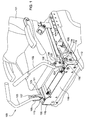
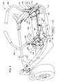
- the ZTR mower may have a rear-mounted engine behind operator seat 101. The seat may be mounted over the frame for a seated operator to use left and right control levers, arm or sticks 102, 103, as shown in Figs. 1 and 2 .
- each control lever or stick 102, 103 may be mounted to the ZTR mower so that the lever may pivot forwardly to move a swash plate in a hydrostatic pump in a first direction to cause a drive wheel to rotate forward, or pivot rearwardly to move the swash plate in a second direction to cause the drive wheel to rotate backward.
- Each control lever or stick may have a neutral position in which the corresponding drive wheel is at rest.
- each control lever or stick 102, 103 may be fastened with bolts through bracket or plate 104, 105 to neutral position lever 106, 107.
- Each control lever or stick, and neutral position lever may pivot on a first axis between a forward position, a neutral position and a reverse position. Additionally, while each control lever or stick is in the neutral position, it may pivot on a second axis perpendicular to the first axis between an inboard position and an outboard position.
- control pivots 108, 109 may be connected to neutral position levers 106,107, so that each control pivot can pivot with forward and reverse pivoting of each lever.
- Dampers 110, 111 may be fastened to each control pivot, along with a steering linkage connecting each control pivot to a hydraulic pump.
- each neutral position lever 106, 107 pivots within a T-shaped slot 112, 113.
- the T-shaped slots are located in plates 114, 115 on the opposing sides of platform 119 on the left and right front corners below operator seat 101.
- Each T-shaped slot may have a forward end 116, a rearward end 117, and a laterally outward end 118 at the neutral position.
- Each neutral position lever can pivot between the full forward position at the forward end of the slot, and the full reverse position at the rearward end of the slot.
- the neutral position lever also can pivot outwardly from the neutral position located between full forward and full reverse.
- control stops 120, 121 are mounted on plates 114, 115 alongside the forward/reverse portion or axis of each T-shaped slot 112, 113.
- Each control stop 120, 121 may extend partially over the T-shaped slot, preferably extending over the slot about 5 mm to about 20 mm, between the full forward end and the full reverse end of the slot.
- Each control stop has a shoulder 122, 123 or detent that is positioned inside the width of the T-shaped slot, partially blocking the slot. The shoulder or detent is configured and positioned to extend sufficiently inside the width of the slot to block or resist pivotal movement of a neutral position lever 106, 107 below a minimum forward speed.
- each control stop can block or stop the inside control lever or stick from pivoting to a slower speed, or into neutral or reverse, during turns.
- each control stop may include a detent that can indicate the neutral position lever at the minimum forward speed position until the operator exerts a greater force on the control lever or stick to overcome the latching force.
- Figs. 1-3 dual lever steering controls 100 with control stops 120, 121 are shown during a sharp right turn.
- Left control lever or stick 102 may be pivoted forward so that left neutral position lever 106 moves toward the forward end 116 of left slot 112. As a result, the left drive wheel is at a forward drive position.
- Right control lever or stick 103 is pivoted rearwardly until right neutral position lever 107 contacts shoulder 123 or detent at the minimum forward speed position. With the left control stick at a forward position and the right control stick at minimum forward speed, the ZTR mower can negotiate a sharp right turn without damaging the turf.
- each control stop prevents a control lever or stick from pivoting below a minimum forward speed.
- each T-shaped slot 112, 113 has a greater width than each neutral position lever 106, 107 that pivots within the slot. Because the slot width is greater than the neutral position lever, each control stop may be dimensioned so that it partially blocks the slot. The operator can then move either control lever or stick past the shoulder or detent into neutral or reverse, by moving the control lever or stick outwardly sufficiently to get around the shoulder or detent.
- the width of the shoulder should be less than about 5 to 8 mm, so that a relatively small outward movement of the control lever or stick is required to get past the shoulder.
- control stops 120, 121 are shown in their operating positions. However, in one embodiment, each control stop 120, 121 may also be moved to a non-operating position where it does not set the minimum forward speed.
- each control stop may be pivotally mounted to plates 114, 115 so that the control stop may be pivoted inwardly to a non-operating position.
- pivot points 124, 125 in the form of threaded fasteners, may connect each control stop to one of the plates. To move each control stop from an operating to a non-operating position, it may be pivoted inwardly until it does not extend over the T-shaped slot 112, 113.
- both control stops 120, 121 may be simultaneously pivoted between their operating and non-operating positions using an actuator such as a foot pedal, or an electrical switch and sol enoid.
- an actuator such as a foot pedal, or an electrical switch and sol enoid.
- the control stops In the operating position, the control stops are in a position to indicate the minimum forward speed for the control levers or sticks. In the non-operating position, the control stops do not indicate the minimum forward speed position.
- foot pedal 130 may be used to activate the control stops.
- the foot pedal may be biased to a position in which the control stops are in their operating positions, and may be depressed to move the control stops into their non-operating positions. Alternatively, the foot pedal may be depressed to move the control stops from the inoperative position to the operative position.
- the pedal may be connected to cable 131, which turns crank 135.
- solenoid 140 may be attached to platform 119, and may be wired to switch 141 and battery 142. When the switch is actuated, the solenoid may turn crank 145, pulling left and right control stop links 146, 147 laterally inwardly. Each control stop link is connected to a control stop which can pivot to a non-operating position.
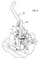
- left control lever 102 is shown with control stop 150.
- Control stop 150 is mounted on plate 114 at the reverse end of the T-shaped slot. In the operating position, the control stop may provide a minimum forward speed.
- the control stop may be positioned to block or resist pivotal movement of neutral position lever 106 below a minimum forward speed. By locating the control stop at a minimum forward speed position, the control stop can block or stop the inside control lever or stick from pivoting to a slower speed, or into neutral or reverse, during turns.
- the minimum forward speed position of the control stop may be set by adjustable cam 152.
- the adjustable cam may pivot to provide a camming surface that locates the control stop at the neutral position lever at the minimum forward speed position until the operator exerts a greater force on the control lever or stick to overcome the control stop.
- control stop 150 may be pivotally mounted to plate 115 and biased to the minimum speed position set by adjustable cam 152.
- pivot point 151 in the form of a threaded fastener, may connect the control stop to the plate.
- Spring 153 and/or damper (not shown) may urge control stop 150 against adjustable cam 152.
- the control stop may be pivoted rearwardly below the mimum speed position and/or into neutral or reverse, if the operator provides sufficient force on the lever or stick to overcome the spring and/or damper.
- the minimum speed position of each control stop, and the bias urging the control stop to that position may be independently adjustable.
Landscapes
- Life Sciences & Earth Sciences (AREA)
- Environmental Sciences (AREA)
- Harvester Elements (AREA)
- Non-Deflectable Wheels, Steering Of Trailers, Or Other Steering (AREA)
Applications Claiming Priority (1)
| Application Number | Priority Date | Filing Date | Title |
|---|---|---|---|
| US11/846,660 US8087481B2 (en) | 2007-08-29 | 2007-08-29 | Dual lever steering controls with control stops |
Publications (3)
| Publication Number | Publication Date |
|---|---|
| EP2030497A2 true EP2030497A2 (fr) | 2009-03-04 |
| EP2030497A3 EP2030497A3 (fr) | 2013-09-25 |
| EP2030497B1 EP2030497B1 (fr) | 2017-02-15 |
Family
ID=40092087
Family Applications (1)
| Application Number | Title | Priority Date | Filing Date |
|---|---|---|---|
| EP08162279.7A Ceased EP2030497B1 (fr) | 2007-08-29 | 2008-08-13 | Contrôles de direction à double levier avec des arrêts de contrôle |
Country Status (2)
| Country | Link |
|---|---|
| US (1) | US8087481B2 (fr) |
| EP (1) | EP2030497B1 (fr) |
Families Citing this family (21)
| Publication number | Priority date | Publication date | Assignee | Title |
|---|---|---|---|---|
| WO2013002780A1 (fr) * | 2011-06-29 | 2013-01-03 | Husqvarna Consumer Outdoor Products N.A., Inc. | Ensemble de direction réglable pour véhicule d'entretien des pelouses |
| US9285028B2 (en) * | 2012-03-19 | 2016-03-15 | Kubota Corporation | Self-propelling work vehicle for forward and reverse drive |
| US8887840B2 (en) * | 2012-08-08 | 2014-11-18 | Swisher Acquisition, Inc. | Zero-turn lawnmower with improved control handles |
| US9510503B2 (en) * | 2012-10-17 | 2016-12-06 | Deere & Company | Grass mowing machine operator platform |
| US8794660B1 (en) | 2013-02-27 | 2014-08-05 | The Toro Company | Ride-on vehicle with operator access assist bar |
| US9682723B2 (en) * | 2013-12-02 | 2017-06-20 | J. Keith Weinlader | Control linkage for hydrostatic drives on lawn mowers |
| US9988084B2 (en) | 2015-02-20 | 2018-06-05 | Barreto Manufacturing, Inc. | Controls for vehicles |
| US9538706B2 (en) | 2015-04-17 | 2017-01-10 | Deere & Company | Zero turn mower steering system |
| US10321627B1 (en) | 2017-12-14 | 2019-06-18 | Schiller Grounds Care, Inc. | Adjustable machine handle assembly |
| US11357170B1 (en) | 2018-08-24 | 2022-06-14 | Excel Industries, Inc. | Steering lever pivot assembly for terrain working vehicle |
| US11091200B2 (en) | 2019-02-21 | 2021-08-17 | Deere & Company | Zero turning radius mower steering lever modules |
| US12296694B2 (en) | 2021-03-10 | 2025-05-13 | Techtronic Cordless Gp | Lawnmowers |
| US12677737B2 (en) | 2021-03-10 | 2026-07-14 | Techtronic Cordless Gp | Lawnmowers |
| US12690518B2 (en) | 2021-03-10 | 2026-07-28 | Techtronic Cordless Gp | Lawnmower with airflow boost system |
| WO2023028453A1 (fr) * | 2021-08-23 | 2023-03-02 | Ariens Company | Raccord hirth multiple pour commandes de tondeuse à gazon |
| USD1015381S1 (en) | 2022-02-14 | 2024-02-20 | Techtronic Cordless Gp | Lawn mower |
| USD1014568S1 (en) | 2022-02-14 | 2024-02-13 | Techtronic Cordless Gp | Lawn mower |
| US12557732B2 (en) | 2022-03-30 | 2026-02-24 | Husqvarna Ab | Return to neutral assembly |
| US12616091B2 (en) * | 2022-10-10 | 2026-05-05 | Havener Enterprises, Inc. | Method and apparatus for height adjustable handles for mower |
| US12477976B1 (en) | 2023-06-06 | 2025-11-25 | Deere & Company | Steering arm return to neutral mechanism |
| US12507624B2 (en) | 2024-04-05 | 2025-12-30 | Kubota Corporation | Adjustable machine handle assembly and mower |
Citations (1)
| Publication number | Priority date | Publication date | Assignee | Title |
|---|---|---|---|---|
| US6161637A (en) | 1998-08-05 | 2000-12-19 | The Toro Company | Twin stick control system |
Family Cites Families (10)
| Publication number | Priority date | Publication date | Assignee | Title |
|---|---|---|---|---|
| US4505067A (en) * | 1983-05-23 | 1985-03-19 | Gillespie John L | Apparatus for hydraulic tree injection |
| US5181592A (en) * | 1990-06-11 | 1993-01-26 | Sparton Corporation | Shift lever interlock system |
| US5228360A (en) * | 1991-07-26 | 1993-07-20 | The Toro Company | Cruise/speed control system for hydrostatic drive |
| US5727426A (en) * | 1996-04-12 | 1998-03-17 | Case Corporation | Mechanism for selecting limits of travel of a lever |
| US6434917B1 (en) * | 2001-04-13 | 2002-08-20 | Excel Industries, Inc. | Mower with combined steering and brake levers |
| JP3894757B2 (ja) * | 2001-09-07 | 2007-03-22 | 株式会社クボタ | 乗用型草刈り機 |
| US6729115B2 (en) * | 2002-04-13 | 2004-05-04 | Excel Industries, Inc. | Mower with combined steering an brake levers |
| JP4518869B2 (ja) * | 2004-08-23 | 2010-08-04 | トヨタ自動車株式会社 | 車両用シフトロック装置 |
| US7299610B2 (en) * | 2005-02-10 | 2007-11-27 | Great Plains Manufacturing, Incorporated | Park/drive mechanical interlock system for zero turn radius mowers |
| US7458432B2 (en) * | 2006-06-16 | 2008-12-02 | Deere & Company | Dual lever steering control mechanism |
-
2007
- 2007-08-29 US US11/846,660 patent/US8087481B2/en active Active
-
2008
- 2008-08-13 EP EP08162279.7A patent/EP2030497B1/fr not_active Ceased
Patent Citations (1)
| Publication number | Priority date | Publication date | Assignee | Title |
|---|---|---|---|---|
| US6161637A (en) | 1998-08-05 | 2000-12-19 | The Toro Company | Twin stick control system |
Also Published As
| Publication number | Publication date |
|---|---|
| US20090056492A1 (en) | 2009-03-05 |
| EP2030497A3 (fr) | 2013-09-25 |
| US8087481B2 (en) | 2012-01-03 |
| EP2030497B1 (fr) | 2017-02-15 |
Similar Documents
| Publication | Publication Date | Title |
|---|---|---|
| US8087481B2 (en) | Dual lever steering controls with control stops | |
| US8235151B2 (en) | Return to neutral control mechanism for zero turning radius mower | |
| US10681867B2 (en) | Zero turning radius mower park brake system | |
| EP1867227B1 (fr) | Mécanisme de contrôle de direction à double levier | |
| AU785332B2 (en) | Walk-behind, self-propelled working machine | |
| US5822961A (en) | Quick adjustment for straight ahead travel for a wheel-steered lawn mower | |
| US7634953B2 (en) | Neutral adjustment mechanism for dual lever steering controls | |
| US5913802A (en) | Single lever drivewheel steering power lawn mower | |
| US7624996B2 (en) | Walk-behind lawn mower sulky latch assembly | |
| US5511367A (en) | Lawn mower having additinal improved trim featuure | |
| US7647754B2 (en) | Walk behind lawn mower control system | |
| US6973768B2 (en) | Mid-mount mower having a mower unit disposed between front and rear wheels | |
| US8573368B2 (en) | Motor driven parking brake actuator system for mower | |
| US9963065B2 (en) | Zero turn mower light system | |
| KR101243409B1 (ko) | 보행형 작업 기계 | |
| US7353651B2 (en) | De-stroking dual hydrostatic pump | |
| GB2627341A (en) | Zero turning radius mower steering sensor linkage | |
| US9682723B2 (en) | Control linkage for hydrostatic drives on lawn mowers | |
| EP3968751B1 (fr) | Véhicule d'entretien de pelouse doté de roues pivotantes d'entraînement avant | |
| US12409821B2 (en) | Zero turning radius mower park brake system | |
| US12181041B2 (en) | Zero turning radius mower park brake system | |
| US12477976B1 (en) | Steering arm return to neutral mechanism | |
| CN223100463U (zh) | 一种双输出农用作业机 | |
| JPS6343887Y2 (fr) | ||
| IE20020428A1 (en) | Verge trimming apparatus |
Legal Events
| Date | Code | Title | Description |
|---|---|---|---|
| PUAI | Public reference made under article 153(3) epc to a published international application that has entered the european phase |
Free format text: ORIGINAL CODE: 0009012 |
|
| AK | Designated contracting states |
Kind code of ref document: A2 Designated state(s): AT BE BG CH CY CZ DE DK EE ES FI FR GB GR HR HU IE IS IT LI LT LU LV MC MT NL NO PL PT RO SE SI SK TR |
|
| AX | Request for extension of the european patent |
Extension state: AL BA MK RS |
|
| PUAL | Search report despatched |
Free format text: ORIGINAL CODE: 0009013 |
|
| AK | Designated contracting states |
Kind code of ref document: A3 Designated state(s): AT BE BG CH CY CZ DE DK EE ES FI FR GB GR HR HU IE IS IT LI LT LU LV MC MT NL NO PL PT RO SE SI SK TR |
|
| AX | Request for extension of the european patent |
Extension state: AL BA MK RS |
|
| RIC1 | Information provided on ipc code assigned before grant |
Ipc: A01D 34/64 20060101ALI20130821BHEP Ipc: A01D 34/68 20060101ALI20130821BHEP Ipc: A01D 34/69 20060101AFI20130821BHEP |
|
| 17P | Request for examination filed |
Effective date: 20140325 |
|
| RBV | Designated contracting states (corrected) |
Designated state(s): AT BE BG CH CY CZ DE DK EE ES FI FR GB GR HR HU IE IS IT LI LT LU LV MC MT NL NO PL PT RO SE SI SK TR |
|
| AKX | Designation fees paid |
Designated state(s): DE GB |
|
| 17Q | First examination report despatched |
Effective date: 20151208 |
|
| GRAP | Despatch of communication of intention to grant a patent |
Free format text: ORIGINAL CODE: EPIDOSNIGR1 |
|
| INTG | Intention to grant announced |
Effective date: 20160822 |
|
| GRAS | Grant fee paid |
Free format text: ORIGINAL CODE: EPIDOSNIGR3 |
|
| GRAA | (expected) grant |
Free format text: ORIGINAL CODE: 0009210 |
|
| AK | Designated contracting states |
Kind code of ref document: B1 Designated state(s): DE GB |
|
| REG | Reference to a national code |
Ref country code: GB Ref legal event code: FG4D |
|
| REG | Reference to a national code |
Ref country code: DE Ref legal event code: R096 Ref document number: 602008048747 Country of ref document: DE |
|
| REG | Reference to a national code |
Ref country code: DE Ref legal event code: R097 Ref document number: 602008048747 Country of ref document: DE |
|
| PLBE | No opposition filed within time limit |
Free format text: ORIGINAL CODE: 0009261 |
|
| STAA | Information on the status of an ep patent application or granted ep patent |
Free format text: STATUS: NO OPPOSITION FILED WITHIN TIME LIMIT |
|
| 26N | No opposition filed |
Effective date: 20171116 |
|
| PGFP | Annual fee paid to national office [announced via postgrant information from national office to epo] |
Ref country code: DE Payment date: 20190719 Year of fee payment: 12 |
|
| REG | Reference to a national code |
Ref country code: DE Ref legal event code: R119 Ref document number: 602008048747 Country of ref document: DE |
|
| PG25 | Lapsed in a contracting state [announced via postgrant information from national office to epo] |
Ref country code: DE Free format text: LAPSE BECAUSE OF NON-PAYMENT OF DUE FEES Effective date: 20210302 |
|
| PGFP | Annual fee paid to national office [announced via postgrant information from national office to epo] |
Ref country code: GB Payment date: 20240827 Year of fee payment: 17 |
|
| GBPC | Gb: european patent ceased through non-payment of renewal fee |
Effective date: 20250813 |
|
| PG25 | Lapsed in a contracting state [announced via postgrant information from national office to epo] |
Ref country code: GB Free format text: LAPSE BECAUSE OF NON-PAYMENT OF DUE FEES Effective date: 20250813 |