EP2030525A2 - Mécanisme de verrouillage - Google Patents
Mécanisme de verrouillage Download PDFInfo
- Publication number
- EP2030525A2 EP2030525A2 EP20080015535 EP08015535A EP2030525A2 EP 2030525 A2 EP2030525 A2 EP 2030525A2 EP 20080015535 EP20080015535 EP 20080015535 EP 08015535 A EP08015535 A EP 08015535A EP 2030525 A2 EP2030525 A2 EP 2030525A2
- Authority
- EP
- European Patent Office
- Prior art keywords
- handle
- locking mechanism
- shaft
- elliptical
- elliptical tip
- Prior art date
- Legal status (The legal status is an assumption and is not a legal conclusion. Google has not performed a legal analysis and makes no representation as to the accuracy of the status listed.)
- Withdrawn
Links
- 230000007246 mechanism Effects 0.000 title claims abstract description 40
- 238000005452 bending Methods 0.000 description 3
- 230000001680 brushing effect Effects 0.000 description 2
- 238000003780 insertion Methods 0.000 description 2
- 230000037431 insertion Effects 0.000 description 2
- 238000000034 method Methods 0.000 description 2
- 230000000717 retained effect Effects 0.000 description 2
- 239000004677 Nylon Substances 0.000 description 1
- 238000004140 cleaning Methods 0.000 description 1
- 230000007812 deficiency Effects 0.000 description 1
- 230000004438 eyesight Effects 0.000 description 1
- 230000009975 flexible effect Effects 0.000 description 1
- 239000003292 glue Substances 0.000 description 1
- 238000009434 installation Methods 0.000 description 1
- 239000000463 material Substances 0.000 description 1
- 229920001778 nylon Polymers 0.000 description 1
- 230000004393 visual impairment Effects 0.000 description 1
- XLYOFNOQVPJJNP-UHFFFAOYSA-N water Substances O XLYOFNOQVPJJNP-UHFFFAOYSA-N 0.000 description 1
Images

Classifications
-
- A—HUMAN NECESSITIES
- A46—BRUSHWARE
- A46B—BRUSHES
- A46B7/00—Bristle carriers arranged in the brush body
- A46B7/04—Bristle carriers arranged in the brush body interchangeably removable bristle carriers
-
- A—HUMAN NECESSITIES
- A46—BRUSHWARE
- A46B—BRUSHES
- A46B5/00—Brush bodies; Handles integral with brushware
- A46B5/0095—Removable or interchangeable brush heads
-
- A—HUMAN NECESSITIES
- A46—BRUSHWARE
- A46B—BRUSHES
- A46B2200/00—Brushes characterized by their functions, uses or applications
- A46B2200/10—For human or animal care
- A46B2200/1066—Toothbrush for cleaning the teeth or dentures
-
- Y—GENERAL TAGGING OF NEW TECHNOLOGICAL DEVELOPMENTS; GENERAL TAGGING OF CROSS-SECTIONAL TECHNOLOGIES SPANNING OVER SEVERAL SECTIONS OF THE IPC; TECHNICAL SUBJECTS COVERED BY FORMER USPC CROSS-REFERENCE ART COLLECTIONS [XRACs] AND DIGESTS
- Y10—TECHNICAL SUBJECTS COVERED BY FORMER USPC
- Y10T—TECHNICAL SUBJECTS COVERED BY FORMER US CLASSIFICATION
- Y10T70/00—Locks
- Y10T70/50—Special application
- Y10T70/5611—For control and machine elements
- Y10T70/5757—Handle, handwheel or knob
- Y10T70/5832—Lock and handle assembly
Definitions
- the present invention relates generally to locking mechanisms and more specifically to a locking mechanism positioned inside a toothbrush handle having interchangeable heads.
- the present invention relates to the art of dental instruments. It finds more particular application in a disposable toothbrush where one would only have to dispose, replace, or interchange the top (brush) portion of the toothbrush.
- the handle or gripping section was made from an expensive material, the handle or gripping portion had an ornamental design, or the top section had multiple instrumentalities or replacements.
- the top section can have different nylon bristle stiffness replacements or interchangeable picking devices and brushes.
- connection devices required a lot of strength or coordination to operate.
- connection or attachment devices to connect the top and bottom portions together.
- male/female devices which are inserted into each other
- threaded devices which screw together
- sliding devices which slide and lock together, similar to the male/female devices, and others known to those skilled in the art.
- Regular toothbrushes are commonly comprised of a handle having a bristle holder at one end, and bundles of bristles installed in the bristle holder.
- This structure of toothbrush is inconvenient for use by an adult to clean the teeth of a baby or young child.
- In order to clean the back teeth in a child's mouth it needs to be opened widely so that the bristles of the toothbrush can reach the back teeth.
- the requirement to have the child's mouth open widely is uncomfortable at best for an adult and for a child as well.
- an interdental brush with a handle that can interchangeably receive and carry different types of brushes.
- the handle has a hinged two-part locking retainer on the end of an elongated handle.
- the first part of the hinged locking retainer is integral with the handle and the second part is arranged to be folded back and retained adjacent to the first part.
- the locking retainer has a through hole located in the second part close to the hinge-axis and being arranged to receive the twisted wire forming the stem of the twisted wire brush.
- the handle has a hinged two-part locking retainer on the end of an elongated handle.
- the first part of the hinged locking retainer is integral with the handle and the second part is arranged to be folded back and retained adjacent the first part.
- the first part has two sidewalls arranged to extend on both sides of the second part in the folded position of the locking retainer.
- One of the sidewalls has a V-shaped gap for receiving the twisted wire stem of the brush. As the locking retainer is closed, the twisted wire stem is frictionally captured and clamped between the first and second part of the hinged locking retainer.
- the locking retainer In order for the friction to be high enough, the locking retainer must exert a clamping force of high magnitude, which in turn implies that the locking retainer must be rigid and therefore also relatively large. The high magnitude of the clamping force also implies that the force needed to close the locking retainer is of considerable magnitude, which may be a problem, especially for older people.
- a key may be interconnected to the receiving means to permit the elliptical tip to rotate.
- the elliptical tip In a first position, the elliptical tip permits the removal and replacement of an interchangeable head, because the longer dimensions of the elliptical tip and an elliptically cross-sectioned opening in the interchangeable head coincide.
- a second, rotated position the elliptical tip locks within the interchangeable head, as the longer dimensions no longer coincide.
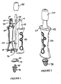
- a shaft 10 of the locking mechanism having an elliptical tip 20 at one end and receiving means 30 at the opposite end.
- the shaft 10 also has a first cam 40 and a second cam 50 to facilitate the positioning of the shaft 10 within a handle 60 (not shown) having body panels 62 and 64.
- the locking mechanism of the present invention has a plug 70 having flanges 80 for interconnecting with the receiving means 30 .
- the key 90 of the locking mechanism of the present invention according to one embodiment has a tongue 95 for insertion into the plug 70 and receiving means 30 of the shaft 10.
- the body panels 62 and 64 are symmetrical to one another for ease of assembly.
- the body panel 64 has protrusions 100 for interconnecting with body panel 62 .
- Body panel 64 has a first receiving means 110 to secure cam 40 from shaft 10 once installed in body panel 64 .
- Body panel 64 also has a second receiving means 120 for cam 50 from shaft 10 once installed in body panel 64.
- a third receiving means 125 enables the shaft 10 to be positioned in the body panel 64 without the use of a cam.
- Body panel 62 has symmetrical receiving means as found on body panel 64 and a worker skilled in the relevant art would be familiar with such symmetrical receiving means in order to allow for the proper installation of the locking mechanism of the present invention within a handle.
- the interchangeable head 130 which has an elliptical opening 140 (not shown) on its underside, can be positioned on the elliptical tip 20 of the locking mechanism according to one embodiment of the present invention.
- the elliptical opening 140 overlaps the handle 60 top, which is also elliptical in cross-section.
- the interchangeable tip 130 is prevented from rotating due to this elliptically cross-sectional overlap.
- the interchangeable head 130 is used for cleaning teeth, and may contain a variety of features in this regard, well-known to one skilled in the art but not detailed here.
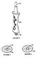
- the handle 60 is shown with body panels 62 and 64 assembled and containing the locking mechanism of the present invention.
- the interchangeable head 130 is positioned on the elliptical tip 20 (not shown) of the shaft 10 (not shown).
- the key 90 of the locking mechanism is shown at the bottom of handle 60.
- handle 60 and the elliptical tip 20 are shown with interchangeable head 130 (not shown) removed.
- the key 90 of the locking mechanism is shown at the bottom of handle 60.
- the elliptical tip 20 is positioned in a locked position wherein the base of tip 20 is perpendicular to the large width of handle 60.
- the elliptical tip 20 is positioned in an unlocked position wherein the base of tip 20 is parallel to the larger width of handle 60.
- the locking mechanism is positioned within the body panel 62.
- the first cam 40 of the shaft 10 is positioned within the receiving means 110 .
- the second cam 50 is positioned within the second receiving means 120 .
- the shaft 10 is positioned in receiving means 125 .
- the use of these receiving means allows for the shaft 10 to be centralized within body panel 62 , and rotate freely within the handle 60 (not shown).
- Protrusions 100 extend from body panel 62 to receive second body panel 64 (not shown) and hold it in place. This method of assembly is well-known to one skilled in the art, and he or she would know that assembly may be accomplished by various other means as well.
- the key 90 of the locking mechanism of the present invention is interconnected with the plug 70 and receiving means 30 .
- the elliptical tip 20 of the shaft 10 is positioned in an unlocked position relative to the interchangeable head 130, meaning that the interchangeable head 130 may be removed from the elliptical tip 20.
- the locking mechanism is locked by turning the key 90 ninety degrees from its unlocked position, as shown in Fig. 8 .
- the key 90 may be a simple as a screwdriver or coin, or more complex, in order to prevent the interchangeable head 130 from separating from the handle 60 while in the mouth of a child, for example.
- the elliptical tip 20 of the shaft 10 is positioned within an interchangeable head 130 in an unlocked position.
- the elliptical tip 20 is inserted into the interchangeable head 130 through opening 140 .
- the interchangeable head 130 is elliptical in cross-section and has flexible properties as would be known by a worker skilled in the relevant art allowing for the elliptical tip 20 to be inserted within the interchangeable head 130 .
- the longer dimensions of the elliptical tip 20 and opening 140 coincide.
- the top of the handle has an elliptical cross-section, and the opening 140 of the interchangeable head 130, which is elliptical in cross-section, fits over the top of the handle such that the interchangeable head 130 cannot rotate independently of the handle 60 .
- the opening 140 contains a lip (not shown) within its opening, such that when the elliptical tip 20 is rotated ninety degrees to a locked position, the elliptical tip 20 is locked within the opening 140 and cannot pass out of the opening, because the longer dimensions of the ellipses do not coincide.
- the locking mechanism is positioned within the body panel 64.
- the elliptical tip 20 is shown in a locked position within interchangeable head 130 which prevents the insertion or removal of the elliptical tip 20 or from the head 130 .
- the key 90 of the locking mechanism is interconnected with the plug 70 and receiving means 30 .
- the elliptical tip 20 of the shaft 10 is positioned within the opening 140 in a locked position.
- the opening 140 is elliptical in cross-section, and opens up to a cylindrical chamber (not shown) within the interchangeable head 130 , which chamber is the length of the elliptical tip 20 with a diameter equal to the longer dimension of the cross-section of the elliptical tip 20 .
- two ledges necessarily appear within the interchangeable head, at the junction between the opening 140 and cylindrical chamber (not shown), where the cylindrical chamber (not shown) opens from the elliptically cross-sectional opening. It is on these two ledges that the base of the elliptical tip rests when in a rotated (locked) position, which prevents the interchangeable head 130 from being removed from the elliptical tip 20 and handle 60.
- the longer dimension of elliptical tip 20 is perpendicular to the longer dimension of elliptical cross-sectioned opening 140 which allows for the interchangeable head 130 to be locked onto the elliptical tip 20.
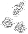
- body panel 64 and plug 70 are shown interconnected.
- Receiving means 120 are also shown in body panel 64 to receive cam 50 (not shown).
- Protrusions 100 are also shown at the bottom of body panel 64 for interconnection with body panel 62 (not shown).
- Flanges 80 extend away from plug 70 for interconnection with receiving means 30 (not shown).
- Stop means 150 are positioned on flanges 80 in order to control the movement of shaft 10 (not shown) from an unlocked to locked position. Stop means 150 consist of precisely positioned flange extensions on flanges 80 .
- the shaft 10 , plug 70 and key 90 are shown in alignment for interconnection with one another.
- the receiving means 30 of the shaft 10 interconnects with flanges 80 of the plug 70 and the key 90 interconnects with the plug 70 through tongue 95 and plug opening 160 .
- Tongue 95 also interconnect with keyhole 170 in receiving means 30 which allows for the movement of the shaft 10 from an unlocked to locked position.
- Control means 180 on receiving means 30 interact with stop means 150 on flanges 80 to limit the movement of shaft 10 between unlocked to locked positions.
- body panel 64 , shaft 10 and plug 70 are interconnected with one another.
- the shaft 10 is positioned within the body panel 62 through cam 50 located in receiving means 120.
- the plug 70 is fixed to body panel 64 through a clip mechanism, for example, or other means of attachment as would be known by a worker skilled in the relevant art.
- Protrusions 100 are shown and enabled the interconnection of body panel 64 with body panel 62 (not shown).
- Stop means 150 interact with control means 180 permitting the shaft 10 to move between unlocked and locked positions.
Landscapes
- Cleaning Implements For Floors, Carpets, Furniture, Walls, And The Like (AREA)
- Brushes (AREA)
Applications Claiming Priority (1)
| Application Number | Priority Date | Filing Date | Title |
|---|---|---|---|
| US96969007P | 2007-09-03 | 2007-09-03 |
Publications (2)
| Publication Number | Publication Date |
|---|---|
| EP2030525A2 true EP2030525A2 (fr) | 2009-03-04 |
| EP2030525A3 EP2030525A3 (fr) | 2010-11-10 |
Family
ID=40119290
Family Applications (1)
| Application Number | Title | Priority Date | Filing Date |
|---|---|---|---|
| EP20080015535 Withdrawn EP2030525A3 (fr) | 2007-09-03 | 2008-09-03 | Mécanisme de verrouillage |
Country Status (3)
| Country | Link |
|---|---|
| US (1) | US20090173116A1 (fr) |
| EP (1) | EP2030525A3 (fr) |
| CA (1) | CA2639269A1 (fr) |
Citations (2)
| Publication number | Priority date | Publication date | Assignee | Title |
|---|---|---|---|---|
| US5201091A (en) | 1990-02-06 | 1993-04-13 | John O. Butler Company | Toothbrush |
| US5758382A (en) | 1995-09-12 | 1998-06-02 | John O. Butler Company, Inc. | Interdental brush handle |
Family Cites Families (8)
| Publication number | Priority date | Publication date | Assignee | Title |
|---|---|---|---|---|
| US1519929A (en) * | 1923-06-09 | 1924-12-16 | Jr Frederick H Rascher | Paintbrush |
| US4705423A (en) * | 1986-06-16 | 1987-11-10 | Kevin Smith | Integral frame connecting apparatus |
| DE4141891C2 (de) * | 1991-12-18 | 1996-07-04 | Johnson & Johnson Ag | Zahnbürste |
| IT244302Y1 (it) * | 1998-10-14 | 2002-03-11 | Bogani Giuseppe | Accoppiamento separabile fra un manico ed elementi di pentolame |
| US6230357B1 (en) * | 1998-12-10 | 2001-05-15 | Art Davis | Paintbrush handle and applicator cartridge |
| US6546633B1 (en) * | 2000-08-11 | 2003-04-15 | Black & Decker Inc. | Reciprocating saw holder |
| US20040200748A1 (en) * | 2003-04-11 | 2004-10-14 | Klassen Lamberta A. M. | Children's tooth and gum cleaning kit |
| US20050079010A1 (en) * | 2003-10-14 | 2005-04-14 | Droppleman J. Patrick | Mechanical connector |
-
2008
- 2008-09-03 CA CA 2639269 patent/CA2639269A1/fr not_active Abandoned
- 2008-09-03 US US12/203,144 patent/US20090173116A1/en not_active Abandoned
- 2008-09-03 EP EP20080015535 patent/EP2030525A3/fr not_active Withdrawn
Patent Citations (2)
| Publication number | Priority date | Publication date | Assignee | Title |
|---|---|---|---|---|
| US5201091A (en) | 1990-02-06 | 1993-04-13 | John O. Butler Company | Toothbrush |
| US5758382A (en) | 1995-09-12 | 1998-06-02 | John O. Butler Company, Inc. | Interdental brush handle |
Also Published As
| Publication number | Publication date |
|---|---|
| US20090173116A1 (en) | 2009-07-09 |
| CA2639269A1 (fr) | 2009-03-03 |
| EP2030525A3 (fr) | 2010-11-10 |
Similar Documents
| Publication | Publication Date | Title |
|---|---|---|
| US5934295A (en) | Dental hygiene system | |
| EP4021245B1 (fr) | Tête de recharge pour soins buccaux | |
| US5224234A (en) | Toothbrush with replaceable bristles | |
| US4780923A (en) | Interproximal brush device having hinged brush retainer cap | |
| AU2020482776B2 (en) | Oral care implement, handle thereof, and oral care refill head therefor | |
| US5896615A (en) | Interdental brush | |
| US8025068B2 (en) | Flossing and oral hygiene tool | |
| KR102569015B1 (ko) | 복합 기능을 갖는 구강 관리 칫솔 | |
| US6170111B1 (en) | Teeth-cleaning device with a handle | |
| TWM555209U (zh) | 可替換潔牙組 | |
| US11013584B2 (en) | Oral hygiene instrument | |
| KR20200052539A (ko) | 치실 홀더 | |
| AU637865B2 (en) | Interdental toothbrush handle | |
| US20090173116A1 (en) | Locking Mechanism | |
| JPH09121942A (ja) | 歯間ブラシ | |
| JP7437308B2 (ja) | デンタルクリーニングシステム、基体、および、デンタルフロス用保持具 | |
| US6681436B2 (en) | Toothbrush including retainer and detachable brush | |
| KR200334842Y1 (ko) | 다목적 분리형칫솔 | |
| KR200377277Y1 (ko) | 칫솔 | |
| US20210000578A1 (en) | Dental floss insertion device | |
| WO2011078523A2 (fr) | Porte-fil de soie dentaire | |
| CA1288206C (fr) | Dispositif a pinceau interproximal a capuchon de retenue du pinceau | |
| GB2277254A (en) | Interdental toothbrush | |
| KR200186931Y1 (ko) | 칫솔모의 분리가 가능한 칫솔 | |
| KR20120000595U (ko) | 휴대용 양면 칫솔 |
Legal Events
| Date | Code | Title | Description |
|---|---|---|---|
| PUAI | Public reference made under article 153(3) epc to a published international application that has entered the european phase |
Free format text: ORIGINAL CODE: 0009012 |
|
| AK | Designated contracting states |
Kind code of ref document: A2 Designated state(s): AT BE BG CH CY CZ DE DK EE ES FI FR GB GR HR HU IE IS IT LI LT LU LV MC MT NL NO PL PT RO SE SI SK TR |
|
| AX | Request for extension of the european patent |
Extension state: AL BA MK RS |
|
| PUAL | Search report despatched |
Free format text: ORIGINAL CODE: 0009013 |
|
| AK | Designated contracting states |
Kind code of ref document: A3 Designated state(s): AT BE BG CH CY CZ DE DK EE ES FI FR GB GR HR HU IE IS IT LI LT LU LV MC MT NL NO PL PT RO SE SI SK TR |
|
| AX | Request for extension of the european patent |
Extension state: AL BA MK RS |
|
| REG | Reference to a national code |
Ref country code: DE Ref legal event code: R108 |
|
| AKY | No designation fees paid | ||
| REG | Reference to a national code |
Ref country code: DE Ref legal event code: R108 Effective date: 20110707 |
|
| STAA | Information on the status of an ep patent application or granted ep patent |
Free format text: STATUS: THE APPLICATION IS DEEMED TO BE WITHDRAWN |
|
| 18D | Application deemed to be withdrawn |
Effective date: 20110331 |