EP2030546A2 - Aspirateur vertical - Google Patents
Aspirateur vertical Download PDFInfo
- Publication number
- EP2030546A2 EP2030546A2 EP08014412A EP08014412A EP2030546A2 EP 2030546 A2 EP2030546 A2 EP 2030546A2 EP 08014412 A EP08014412 A EP 08014412A EP 08014412 A EP08014412 A EP 08014412A EP 2030546 A2 EP2030546 A2 EP 2030546A2
- Authority
- EP
- European Patent Office
- Prior art keywords
- vacuum cleaner
- upper body
- housing
- fork
- blower
- Prior art date
- Legal status (The legal status is an assumption and is not a legal conclusion. Google has not performed a legal analysis and makes no representation as to the accuracy of the status listed.)
- Granted
Links
- 239000000428 dust Substances 0.000 claims description 17
- 239000002184 metal Substances 0.000 description 5
- 238000000034 method Methods 0.000 description 3
- 230000008569 process Effects 0.000 description 3
- 238000007789 sealing Methods 0.000 description 3
- 238000004140 cleaning Methods 0.000 description 2
- 238000010276 construction Methods 0.000 description 2
- 238000009434 installation Methods 0.000 description 2
- 238000004519 manufacturing process Methods 0.000 description 2
- 230000007246 mechanism Effects 0.000 description 2
- 239000002245 particle Substances 0.000 description 2
- 238000003860 storage Methods 0.000 description 2
- 230000007704 transition Effects 0.000 description 2
- 240000006829 Ficus sundaica Species 0.000 description 1
- 238000005299 abrasion Methods 0.000 description 1
- 230000000712 assembly Effects 0.000 description 1
- 238000000429 assembly Methods 0.000 description 1
- 230000001680 brushing effect Effects 0.000 description 1
- 230000008859 change Effects 0.000 description 1
- 150000001875 compounds Chemical class 0.000 description 1
- 230000000881 depressing effect Effects 0.000 description 1
- 238000011161 development Methods 0.000 description 1
- 230000018109 developmental process Effects 0.000 description 1
- 230000000694 effects Effects 0.000 description 1
- 238000005304 joining Methods 0.000 description 1
- 239000002689 soil Substances 0.000 description 1
- 239000013589 supplement Substances 0.000 description 1
- 238000003971 tillage Methods 0.000 description 1
- 238000003466 welding Methods 0.000 description 1
Images



Classifications
-
- A—HUMAN NECESSITIES
- A47—FURNITURE; DOMESTIC ARTICLES OR APPLIANCES; COFFEE MILLS; SPICE MILLS; SUCTION CLEANERS IN GENERAL
- A47L—DOMESTIC WASHING OR CLEANING; SUCTION CLEANERS IN GENERAL
- A47L5/00—Structural features of suction cleaners
- A47L5/12—Structural features of suction cleaners with power-driven air-pumps or air-compressors, e.g. driven by motor vehicle engine vacuum
- A47L5/22—Structural features of suction cleaners with power-driven air-pumps or air-compressors, e.g. driven by motor vehicle engine vacuum with rotary fans
- A47L5/28—Suction cleaners with handles and nozzles fixed on the casings, e.g. wheeled suction cleaners with steering handle
Definitions
- the invention relates to a Upright-type vacuum cleaner with an upper body with dust collection container, with a ground unit, which is movable by a chassis on the surface to be cleaned, and with an engine fan for generating a negative pressure acting on the surface to be cleaned, wherein the engine fan in wherein the bottom unit is arranged and wherein between the upper body and bottom unit, a tilting joint is arranged, by which upper body and bottom unit are mounted to each other about a horizontal axis in use pivotally.
- the following describes three types of vacuum cleaner that differ in their construction and operation. As common features all have a motor-driven blower, a dust collection room and one or more adapted to the particular purpose tillage equipment.
- the vacuum cleaner has a housing which is movable on rollers and / or skids on the ground to be processed.
- the engine fan and the dust collector are arranged in the housing.
- the soil treatment device - here called floor nozzle - is connected via a suction hose, possibly with an intermediate suction pipe, with the dust collection chamber.
- the housing is brought into the desired position during the suction process by pulling on the suction tube.
- the motor fan and the dust collector are also arranged in a housing. From the housing extends on one side of a suction pipe, which connects a floor nozzle with the dust collector, and on the other hand, a handle with which the housing is maneuvered into the desired position.
- An essential feature of an upright is a movable floor unit, which carries a torso with a large dust collector.
- the two parts are pivotally mounted to each other and usually fixable in a parking position in which the upper body is approximately vertical when the ground unit is in the use position on a horizontal ground. In this position, the upright is automatic.
- this locking is released and tilted the upper body by a certain angle in a working position.
- the swivel angle depends on the one hand on the size of the user and on the other hand from the respective use.
- a handle on the upper body is used to guide the entire device.
- the engine fan may be located at various locations.
- Uprights are known in which the engine fan is arranged in the ground unit.
- the articulated connection between the floor unit and the upper body by a hinge-like structure.
- the air is routed through flexible hoses that extend from the floor unit to the upper body.
- the invention thus has the problem to improve it to the effect that it has a robust, yet simple and easy to manufacture structure.
- the advantages achievable with the invention result from the fact that the leading to the suction side of the engine fan air line is rotatably mounted relative to the engine fan. As a result, kinks are avoided on air-carrying hoses.
- the air line forms the fulcrum of the tilting joint, further components are saved for the realization of such a joint and the vacuum cleaner is easy to manufacture.
- the air line then receives a robust construction and can be rotatably mounted on a housing surrounding the motor fan. In this case, the housing may be suitably designed in several parts.
- the air line is provided at its end facing the engine fan with a circumferential seal.
- the seal can advantageously rest on a sleeve-shaped projection, which is formed by at least a portion of the housing.
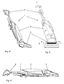
- Upright vacuum cleaner shown in various views, hereinafter referred to as Upright 1, consists essentially of a bottom unit 2, an upper body 3 and a joint arranged therebetween, which will be described later.
- the upright 1 can from an upright position (see FIGS. 1 to 3 ), in which he is latched and then stands free, after releasing the locking (see FIG. 7 ) into a tilted ( FIGS. 4 and 5 ) and even in a fully extended position ( FIG. 6 ) to be brought.
- ground unit 2 and upper body 3 are a horizontal axis X in use (see FIG FIG. 5 ) mounted to each other pivotally.
- the joint which allows the pivoting movement, is referred to below as a tilting joint.
- the upright in the tilted position, as well as in FIG. 5 shown rotated about an axis Y. By rotating the upper body 3 by means of the appliance handle 4 about this axis and simultaneously pushing or pulling the upright, the user can control the floor unit 2 around curves.
- the corresponding joint is referred to in the text as a hinge.
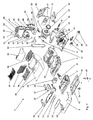
- the ground unit 2 in FIG. 7 shown in exploded view, comprises a housing, which is formed by a housing insert 5, a rear housing lower part 6, a front housing lower part 7, a bumper strip 8 and a cover part 9.
- the housing insert 5 acts as a carrier for a number of electrical and mechanical components, and the aforementioned housing parts are attached to it. It forms with the rear housing lower part 6 with the interposition of an engine compartment seal 10, a space for receiving an engine blower 11, which generates the vacuum necessary for suction operation.
- a sealing ring 13 is arranged around the fan inlet 12, which is also supported on the two aforementioned housing parts 5 and 6.
- rubber buffer 14 are inserted.
- a brushing roller 17 which is resiliently mounted on two lateral wings 18 and 19 and driven by a brush motor 20 via a belt 21.
- the parts 22 and 23 represent a two-piece belt cover.
- the brush motor 20 is also secured to the housing insert 5, the rockers 18 and 19 are pivotally mounted there.
- the two housing bases 6 and 7 carry the chassis of the upright, which is formed of front wheels 24 and 25 and rear wheels 26 and 27.
- the rear wheels 26 and 27 are connected to stabilize by means of an axle 28 and adjustable via a respective wheel mechanism 29 and 30 in their position.
- a board 31 is attached to LED's 32, which is covered to the front by a lens 33.
- the viewing window 33 is held in a recess 34 in the bumper 8.
- the air generated by the engine fan 11 is blown through an opening 35 in the housing insert 5 and a corresponding opening 36 in the cover part 9 in the environment.
- a filter frame 37 is used, which receives a not shown exhaust filter for cleaning the air blown out of fines.
- the filter frame 37 is covered by a grid receptacle 38 and a grid 39 in the lid part 9 and is interchangeable from there.
- Both the tilting joint and the pivot joint between the base unit 2 and the upper body 3 described later are formed by a rigid, fork-shaped channel component.
- This component also includes parts of the air duct from the suction port 15 to the upper body 3 and the air guide from the upper body 3 to the exhaust opening (openings 35 and 36).
- the component is referred to below as fork 40 and is in the Figures 10 and 12 as a detail and in the FIGS. 9 and 9a shown in the installation position. It consists of two plastic parts, an upper shell 41 and a lower shell 42, which are interconnected by welding.
- the two ends 43 (right) and 44 (left) of the fork 40 are pivotally mounted in recesses 45 and 46 provided for this purpose, to avoid abrasion, they are respectively surrounded by metallic bushings 47 and 48.
- the left in the direction of travel fork 44 is designed as hollow and coupled via a seal 49 with the blower inlet 12.
- a bearing pin 50 is formed at the right in the direction of travel fork 43 . It also has an opening 51 which is connected via an elastic tube 52 to the suction port 15.
- the connecting portion of the two fork ends 43 and 44 hereinafter referred to as a fork web 53, surrounded by a front cover 54 and a rear cover 55 on the bottom unit 2, which the pivotal movement of the fork 40 with execute.
- the space between the front and rear cover and the housing insert 5 is bridged by aperture 56 and 57.
- the first 58 of two cable channels 58 and 59 is attached.
- the fork ends 43 and 44 carry toothed segments 60 and 61 which cooperate with the wheel mechanisms 29 and 30.
- a trim cover 62 is attached to a connection cable, not shown.
- a stepping lever 63 is mounted on the housing insert 5, which engages in this position in the left fork end 44 and thus prevents the pivoting movement of the fork 40.
- the locking position can be released.
- the latched position is also prevented by two spring-loaded bolts 64 and 65 a rotational movement.
- the air ducts, which are formed by the fork ends 43 and 44, are combined in the region of the fork web 53 to a first portion 66 of a coaxial line.
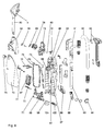
- FIG. 8 shows the upper body 3, also in exploded view.
- Carrying component of the upper body 3 is a rear wall 67. It forms the rear portion of the dust chamber 68, which in turn receives a filter bag, not shown in the drawing.
- the edge of the dust chamber 68 is surrounded by a seal 69, the side of a cover strip 70 is fixed for cables, not shown.
- a hinge bearing 71 is attached to the rear wall 67.
- the dust chamber 68 is closed at the front by an upper housing part 72, which is articulated via hinges 73 and torsion springs 74 pivotally mounted on the hinge bearing 71.
- the upper part 72 carries a closure 75, a dust bag receptacle 76 and a filter change indicator 77.
- the rear wall 67 carries the electronics 78 of Uprights, which is completely arranged on a receptacle 79 and as pre-tested component component is mounted.
- a lever 81 for switching off the brush motor 20 is arranged via a torsion spring 80.
- the electronics 78 is covered by a cap 84, which also serves for attachment to various controls and display elements and their accessories (lens 85, knob 86).
- An elaborate air duct ensures that dirt-laden air can either be sucked in via the suction mouth in the floor unit or via a telescopic tube with possibly connected suction attachments such as crevice nozzle, furniture brush, upholstery nozzle, etc.
- suction air from the suction port 15 via the elastic tube 52 and the right fork end 43 through the inner tube of the first portion 66 of the coaxial line in the fork bridge 53 passed into the inner tube of a second portion 87 of the coaxial line.
- This section 87 is continued in the rear wall 67 and there again separated into two separate lines.
- the further air path leads through a Saugkanal Culture 88 in a manifold 89.
- a telescopic tube 90 inserted, which passes via a pipe handle 91 in a flexible suction hose 92.
- the suction hose 92 is held in a receptacle 93 provided therefor, as well as in FIG. 3 is recognizable.
- Via a pivoting arc 94 the air enters a channel which extends over the entire length of the rear wall 67.
- the channel is formed from the rear wall 67 itself and an attached air duct piece 95.
- an arcuate neck 96 which consists of the rear wall 67 and partly of the electronic receptacle 79, the dirt-laden suction air in the area of the dust bag receptacle 76 and there in a dust bag, not shown.
- FIG. 8 In the lower part of the components that serve for attachment and rotatable mounting of the upper body 3 to the fork 40.
- the first section 66 of the coaxial line is surrounded by an injected metal ring 98, which projects beyond the outer diameter of this section 66 and which is enclosed in two bearing shells 99 and 100, respectively.
- the bearing shells 99 and 100 are connected to the upper body 3.
- metal ring 98 and bearing shells 99 and 100 form the pivot of Uprights 1.
- the two sections 66 and 87 of the coaxial line with the interposition of a seal 101 are assembled.
- FIG. 9 is the engine fan 11 recognizable, which is inserted into the rear housing lower part 6 and is covered by the housing insert 5.
- the housing insert 5 On the suction side of the blower inlet 12 around the sealing ring 13 is arranged, which is also supported on the two aforementioned housing parts 5 and 6.
- the enlarged view in FIG. 9a shows that the housing insert 5 is expanded in the region of the fan inlet 12 into a sleeve-shaped projection 501. As a result, joints of the two housing parts are avoided in this area.
- the right in the direction of travel (out of the plane) fork end 43 in the FIG.
- FIG. 9 shown on the left), as described above, designed as a journal and bordered by a metallic bushing 47. It is absorbed by a closed bearing seat, which is formed during assembly of the rear housing lower part 6 through the recess 45 and a corresponding counterpart 103 of the housing insert 5.
- the Opening 51 can be seen, in which the leading to the suction mouth 15 hose piece (s. FIG. 7 ) is plugged.
- the left in the direction of travel fork 44 (in the FIG. 9 shown on the right) forms both the air flow from the upper body to the suction side of the blower 11 (fan inlet 12) and the pivot point of the tilting joint. It is therefore made hollow and provided at the end with a seal 49.
- the seal 49 bears against the projection 501 and ensures an airtight transition between the blower 11 and the fork end 44. In this way, a high suction force can be achieved.
- the storage takes place as in the right fork end by a bearing bush 48 which is received by a bearing seat (recesses 46 and 104).
- the pivot axis X extends in the axis of symmetry of the engine blower 11, it is shown as a dashed line 102.
- FIGS. 9 to 11 also show the fork web 52, in which the two air lines 105 and 106 from the fork ends 43 and 44 unite to form a first portion 66 of a coaxial line.
- the air line 105 which is formed by the right fork end 43, is passed as an inner tube 107 in the upper body 3.
- This tube 107 has a large flow cross-section, which can easily pass the dirt-laden air and larger parts sucked.
- the line 106 which is formed by the left fork end 44, encloses the inner tube 107 in the fork web 53 and is guided as an outer ring 108 in the upper body 3. This is expedient because the transported air is already cleaned and therefore can be passed through this area with a smaller flow cross-section.
- FIGS. 12 to 16 show the transition region from the fork 40 to the upper body 3 in different representations. It goes without saying that the connection between the fork web 53 on the upper shell 41 and the rear wall 67 takes place only when the two assemblies ground unit 2 and upper body 3 are completely assembled.
- the outer tube 106 of the Koaxial Arthurs section on the fork web 53 is, as already described above, surrounded by an injected metal ring 98, the FIG. 10 shows the outer tube with the ring 98 in the installation situation.
- the coaxial seal 101 is placed on the inner tube 105 and the outer ring 106. Subsequently, the two bearing shells 99 and 100 are connected by screws, not shown around the outer tube 106 and the metal ring 98 together to form a bearing housing 111.
- FIG. 13 shows the upper shell 41 - mentally this is to supplement the other components of the floor unit 2 - after the completion of these assembly steps. Due to its dimensions, the bearing housing 111 can be rotated around the outer ring 106 and the metal ring 98 around, thus resulting in a rotation axis Y, which in the FIGS. 12 to 16 is shown as dashed line 112.
- the two inner tubes 107 and 113 and also the two outer rings 108 and 114 of the Koaxial effets sections 66 and 87 are connected to each other via the seal 101, which in each case has H-shaped cross-sections.
- the above-described storage is defined so that the distance between the ends of the outer rings 108 and 114 and the inner tubes 107 and 113 in the mounted state is greater than the width of the arranged between the tube ends webs 118 of the H-seal 101.
- the two sections 66 and 87 can therefore be rotated freely against each other, it results in only a slight resistance by the contact forces of the sealing walls 119.
- the arrangement of the bearing housing 111 outside the air duct whose exposure to dirt from the suction air is excluded.
Landscapes
- Electric Suction Cleaners (AREA)
- Nozzles For Electric Vacuum Cleaners (AREA)
- Electric Vacuum Cleaner (AREA)
Applications Claiming Priority (1)
| Application Number | Priority Date | Filing Date | Title |
|---|---|---|---|
| DE102007040955A DE102007040955A1 (de) | 2007-08-30 | 2007-08-30 | Upright-Staubsauger |
Publications (3)
| Publication Number | Publication Date |
|---|---|
| EP2030546A2 true EP2030546A2 (fr) | 2009-03-04 |
| EP2030546A3 EP2030546A3 (fr) | 2011-08-24 |
| EP2030546B1 EP2030546B1 (fr) | 2012-10-03 |
Family
ID=40070648
Family Applications (1)
| Application Number | Title | Priority Date | Filing Date |
|---|---|---|---|
| EP08014412A Not-in-force EP2030546B1 (fr) | 2007-08-30 | 2008-08-13 | Aspirateur vertical |
Country Status (3)
| Country | Link |
|---|---|
| US (1) | US8201302B2 (fr) |
| EP (1) | EP2030546B1 (fr) |
| DE (1) | DE102007040955A1 (fr) |
Families Citing this family (12)
| Publication number | Priority date | Publication date | Assignee | Title |
|---|---|---|---|---|
| US7979952B2 (en) * | 2006-12-13 | 2011-07-19 | Ab Electrolux | Wet/dry floor cleaning device |
| DE102007040958A1 (de) * | 2007-08-30 | 2009-03-05 | Miele & Cie. Kg | Upright-Staubsauger |
| DE102007040949A1 (de) * | 2007-08-30 | 2009-03-05 | Miele & Cie. Kg | Upright-Staubsauger |
| DE102007040961A1 (de) * | 2007-08-30 | 2009-03-05 | Miele & Cie. Kg | Upright-Staubsauger |
| DE102007040959A1 (de) * | 2007-08-30 | 2009-03-05 | Miele & Cie. Kg | Upright-Staubsauger |
| CA2953105C (fr) | 2009-07-30 | 2020-02-11 | Omachron Intellectual Property Inc. | Appareil de nettoyage de surfaces |
| CA2674763A1 (fr) * | 2009-07-30 | 2011-01-30 | G.B.D. Corp. | Appareil de nettoyage de surfaces |
| US8667643B2 (en) | 2010-09-10 | 2014-03-11 | Euro-Pro Operating Llc | Method and apparatus for assisting pivot motion of a handle in a floor treatment device |
| US8627545B2 (en) | 2011-03-18 | 2014-01-14 | Panasonic Corporation Of North America | Vacuum cleaner with enhanced maneuverability |
| US20130133155A1 (en) * | 2011-11-28 | 2013-05-30 | Julio C. Perez | Vacuum cleaner incorporating noise suppression system |
| US9060665B2 (en) | 2013-03-01 | 2015-06-23 | Euro-Pro Operating Llc | Floor cleaning appliance |
| US9173533B1 (en) | 2014-06-25 | 2015-11-03 | Emerson Electric Co. | Upright vacuum cleaner |
Citations (3)
| Publication number | Priority date | Publication date | Assignee | Title |
|---|---|---|---|---|
| EP0708613A1 (fr) | 1993-07-09 | 1996-05-01 | The Regina Company | Aspirateur a capacites directionnelles ameliorees |
| WO2004014209A1 (fr) | 2002-08-09 | 2004-02-19 | Dyson Technology Limited | Appareil de traitement de surface |
| WO2007008770A2 (fr) | 2005-07-12 | 2007-01-18 | Bissell Homecare, Inc. | Ensemble vertical d'aspirateur |
Family Cites Families (16)
| Publication number | Priority date | Publication date | Assignee | Title |
|---|---|---|---|---|
| US3932912A (en) | 1974-02-15 | 1976-01-20 | Whirlpool Corporation | Vacuum cleaner |
| US4129920A (en) | 1977-12-12 | 1978-12-19 | Consolidated Foods Corporation | Hose coupling for upright vacuum cleaner |
| US4423534A (en) | 1981-12-14 | 1984-01-03 | Whirlpool Corporation | Vacuum cleaner handle lock |
| DE19525796A1 (de) | 1995-07-15 | 1997-01-23 | Fedag Romanshorn Fa | Zusammengesetzte Saugleitung |
| US5794305A (en) | 1996-12-17 | 1998-08-18 | Weger; Kenneth J. | Articulation device for a vacuum cleaner |
| US6055703A (en) | 1997-10-14 | 2000-05-02 | Oreck Holdings Llc | Upright vacuum cleaner having improved steering apparatus with a lock out feature |
| US6277164B1 (en) * | 1999-04-06 | 2001-08-21 | Oreck Holdings, Llc | Balanced flow vacuum cleaner bag interface |
| US6957472B2 (en) | 1999-05-21 | 2005-10-25 | Vortex Hc, Llc | Cannister and upright vortex vacuum cleaners |
| EP1320318B1 (fr) * | 2000-09-29 | 2012-10-24 | Oreck Holdings, LLC | Ensembles conduits d'aspiration de logement de soufflante profiles pour machines d'entretien des sols |
| DE102004052306A1 (de) | 2004-10-16 | 2006-04-20 | Stein & Co Gmbh | Vorrichtung zur Anordnung eines Saugvorsatzes |
| GB2422094B8 (en) | 2005-01-18 | 2008-06-05 | Dyson Technology Ltd | Surface-treating appliance |
| US20070094839A1 (en) | 2005-11-03 | 2007-05-03 | The Scott Fetzer Company | Cleaning apparatus with removable handle |
| DE102007040959A1 (de) | 2007-08-30 | 2009-03-05 | Miele & Cie. Kg | Upright-Staubsauger |
| DE102007040949A1 (de) | 2007-08-30 | 2009-03-05 | Miele & Cie. Kg | Upright-Staubsauger |
| DE102007040961A1 (de) | 2007-08-30 | 2009-03-05 | Miele & Cie. Kg | Upright-Staubsauger |
| DE102007040958A1 (de) | 2007-08-30 | 2009-03-05 | Miele & Cie. Kg | Upright-Staubsauger |
-
2007
- 2007-08-30 DE DE102007040955A patent/DE102007040955A1/de not_active Withdrawn
-
2008
- 2008-08-13 EP EP08014412A patent/EP2030546B1/fr not_active Not-in-force
- 2008-08-27 US US12/199,464 patent/US8201302B2/en not_active Expired - Fee Related
Patent Citations (3)
| Publication number | Priority date | Publication date | Assignee | Title |
|---|---|---|---|---|
| EP0708613A1 (fr) | 1993-07-09 | 1996-05-01 | The Regina Company | Aspirateur a capacites directionnelles ameliorees |
| WO2004014209A1 (fr) | 2002-08-09 | 2004-02-19 | Dyson Technology Limited | Appareil de traitement de surface |
| WO2007008770A2 (fr) | 2005-07-12 | 2007-01-18 | Bissell Homecare, Inc. | Ensemble vertical d'aspirateur |
Also Published As
| Publication number | Publication date |
|---|---|
| US8201302B2 (en) | 2012-06-19 |
| US20090056063A1 (en) | 2009-03-05 |
| EP2030546A3 (fr) | 2011-08-24 |
| DE102007040955A1 (de) | 2009-03-05 |
| EP2030546B1 (fr) | 2012-10-03 |
Similar Documents
| Publication | Publication Date | Title |
|---|---|---|
| EP2033558B1 (fr) | Aspirateur vertical | |
| EP2030548B1 (fr) | Aspirateur vertical | |
| EP2030544B1 (fr) | Aspirateur vertical | |
| EP2030546B1 (fr) | Aspirateur vertical | |
| EP2030550B1 (fr) | Aspirateur vertical | |
| EP2030547B1 (fr) | Aspirateur vertical | |
| EP2030549B1 (fr) | Aspirateur vertical | |
| EP2030552B1 (fr) | Aspirateur vertical | |
| EP2030551B1 (fr) | Aspirateur vertical | |
| DE19522349C2 (de) | Staubsauger für Doppelbetrieb | |
| EP1407703A2 (fr) | Dispositif de conduit d'air dans une tête de nettoyage d'aspirateur | |
| WO2004058031A1 (fr) | Aspirateur a tiroir pour filtre | |
| DE102009034955B4 (de) | Selbsttätig verfahrbares Bodenstaub-Aufsammelgerät | |
| EP2587977B1 (fr) | Buse pour aspirateur | |
| EP2030553A2 (fr) | Aspirateur vertical | |
| EP2030545B1 (fr) | Aspirateur vertical | |
| DE102007040951B4 (de) | Staubsauger | |
| EP2030554B1 (fr) | Aspirateur doté d'un ventilateur motorisé, dont le filtre fin est pourvu d'un flux d'air de sortie | |
| DE102007040962B4 (de) | Upright-Staubsauger | |
| EP1250880B1 (fr) | Aspirateur avec suceur pivotant | |
| DE202012010452U1 (de) | Bodenreinigungsvorrichtung | |
| DE202012010450U1 (de) | Bodenreinigungsvorrichtung |
Legal Events
| Date | Code | Title | Description |
|---|---|---|---|
| PUAI | Public reference made under article 153(3) epc to a published international application that has entered the european phase |
Free format text: ORIGINAL CODE: 0009012 |
|
| AK | Designated contracting states |
Kind code of ref document: A2 Designated state(s): AT BE BG CH CY CZ DE DK EE ES FI FR GB GR HR HU IE IS IT LI LT LU LV MC MT NL NO PL PT RO SE SI SK TR |
|
| AX | Request for extension of the european patent |
Extension state: AL BA MK RS |
|
| PUAL | Search report despatched |
Free format text: ORIGINAL CODE: 0009013 |
|
| AK | Designated contracting states |
Kind code of ref document: A3 Designated state(s): AT BE BG CH CY CZ DE DK EE ES FI FR GB GR HR HU IE IS IT LI LT LU LV MC MT NL NO PL PT RO SE SI SK TR |
|
| AX | Request for extension of the european patent |
Extension state: AL BA MK RS |
|
| RIC1 | Information provided on ipc code assigned before grant |
Ipc: A47L 5/28 20060101AFI20110719BHEP |
|
| 17P | Request for examination filed |
Effective date: 20111217 |
|
| AKX | Designation fees paid |
Designated state(s): AT BE BG CH CY CZ DE DK EE ES FI FR GB GR HR HU IE IS IT LI LT LU LV MC MT NL NO PL PT RO SE SI SK TR |
|
| GRAP | Despatch of communication of intention to grant a patent |
Free format text: ORIGINAL CODE: EPIDOSNIGR1 |
|
| GRAS | Grant fee paid |
Free format text: ORIGINAL CODE: EPIDOSNIGR3 |
|
| GRAA | (expected) grant |
Free format text: ORIGINAL CODE: 0009210 |
|
| AK | Designated contracting states |
Kind code of ref document: B1 Designated state(s): AT BE BG CH CY CZ DE DK EE ES FI FR GB GR HR HU IE IS IT LI LT LU LV MC MT NL NO PL PT RO SE SI SK TR |
|
| REG | Reference to a national code |
Ref country code: GB Ref legal event code: FG4D Free format text: NOT ENGLISH |
|
| REG | Reference to a national code |
Ref country code: AT Ref legal event code: REF Ref document number: 577579 Country of ref document: AT Kind code of ref document: T Effective date: 20121015 Ref country code: CH Ref legal event code: EP |
|
| REG | Reference to a national code |
Ref country code: IE Ref legal event code: FG4D Free format text: LANGUAGE OF EP DOCUMENT: GERMAN |
|
| REG | Reference to a national code |
Ref country code: DE Ref legal event code: R096 Ref document number: 502008008286 Country of ref document: DE Effective date: 20121129 |
|
| REG | Reference to a national code |
Ref country code: DE Ref legal event code: R084 Ref document number: 502008008286 Country of ref document: DE Effective date: 20121016 |
|
| PG25 | Lapsed in a contracting state [announced via postgrant information from national office to epo] |
Ref country code: SI Free format text: LAPSE BECAUSE OF FAILURE TO SUBMIT A TRANSLATION OF THE DESCRIPTION OR TO PAY THE FEE WITHIN THE PRESCRIBED TIME-LIMIT Effective date: 20121003 |
|
| REG | Reference to a national code |
Ref country code: NL Ref legal event code: VDEP Effective date: 20121003 |
|
| REG | Reference to a national code |
Ref country code: LT Ref legal event code: MG4D |
|
| PG25 | Lapsed in a contracting state [announced via postgrant information from national office to epo] |
Ref country code: LT Free format text: LAPSE BECAUSE OF FAILURE TO SUBMIT A TRANSLATION OF THE DESCRIPTION OR TO PAY THE FEE WITHIN THE PRESCRIBED TIME-LIMIT Effective date: 20121003 Ref country code: FI Free format text: LAPSE BECAUSE OF FAILURE TO SUBMIT A TRANSLATION OF THE DESCRIPTION OR TO PAY THE FEE WITHIN THE PRESCRIBED TIME-LIMIT Effective date: 20121003 Ref country code: IS Free format text: LAPSE BECAUSE OF FAILURE TO SUBMIT A TRANSLATION OF THE DESCRIPTION OR TO PAY THE FEE WITHIN THE PRESCRIBED TIME-LIMIT Effective date: 20130203 Ref country code: NO Free format text: LAPSE BECAUSE OF FAILURE TO SUBMIT A TRANSLATION OF THE DESCRIPTION OR TO PAY THE FEE WITHIN THE PRESCRIBED TIME-LIMIT Effective date: 20130103 Ref country code: NL Free format text: LAPSE BECAUSE OF FAILURE TO SUBMIT A TRANSLATION OF THE DESCRIPTION OR TO PAY THE FEE WITHIN THE PRESCRIBED TIME-LIMIT Effective date: 20121003 Ref country code: ES Free format text: LAPSE BECAUSE OF FAILURE TO SUBMIT A TRANSLATION OF THE DESCRIPTION OR TO PAY THE FEE WITHIN THE PRESCRIBED TIME-LIMIT Effective date: 20130114 Ref country code: HR Free format text: LAPSE BECAUSE OF FAILURE TO SUBMIT A TRANSLATION OF THE DESCRIPTION OR TO PAY THE FEE WITHIN THE PRESCRIBED TIME-LIMIT Effective date: 20121003 Ref country code: SE Free format text: LAPSE BECAUSE OF FAILURE TO SUBMIT A TRANSLATION OF THE DESCRIPTION OR TO PAY THE FEE WITHIN THE PRESCRIBED TIME-LIMIT Effective date: 20121003 |
|
| PG25 | Lapsed in a contracting state [announced via postgrant information from national office to epo] |
Ref country code: PL Free format text: LAPSE BECAUSE OF FAILURE TO SUBMIT A TRANSLATION OF THE DESCRIPTION OR TO PAY THE FEE WITHIN THE PRESCRIBED TIME-LIMIT Effective date: 20121003 Ref country code: PT Free format text: LAPSE BECAUSE OF FAILURE TO SUBMIT A TRANSLATION OF THE DESCRIPTION OR TO PAY THE FEE WITHIN THE PRESCRIBED TIME-LIMIT Effective date: 20130204 Ref country code: LV Free format text: LAPSE BECAUSE OF FAILURE TO SUBMIT A TRANSLATION OF THE DESCRIPTION OR TO PAY THE FEE WITHIN THE PRESCRIBED TIME-LIMIT Effective date: 20121003 Ref country code: GR Free format text: LAPSE BECAUSE OF FAILURE TO SUBMIT A TRANSLATION OF THE DESCRIPTION OR TO PAY THE FEE WITHIN THE PRESCRIBED TIME-LIMIT Effective date: 20130104 |
|
| REG | Reference to a national code |
Ref country code: HU Ref legal event code: AG4A Ref document number: E015917 Country of ref document: HU |
|
| PG25 | Lapsed in a contracting state [announced via postgrant information from national office to epo] |
Ref country code: SK Free format text: LAPSE BECAUSE OF FAILURE TO SUBMIT A TRANSLATION OF THE DESCRIPTION OR TO PAY THE FEE WITHIN THE PRESCRIBED TIME-LIMIT Effective date: 20121003 Ref country code: CZ Free format text: LAPSE BECAUSE OF FAILURE TO SUBMIT A TRANSLATION OF THE DESCRIPTION OR TO PAY THE FEE WITHIN THE PRESCRIBED TIME-LIMIT Effective date: 20121003 Ref country code: BG Free format text: LAPSE BECAUSE OF FAILURE TO SUBMIT A TRANSLATION OF THE DESCRIPTION OR TO PAY THE FEE WITHIN THE PRESCRIBED TIME-LIMIT Effective date: 20130103 Ref country code: EE Free format text: LAPSE BECAUSE OF FAILURE TO SUBMIT A TRANSLATION OF THE DESCRIPTION OR TO PAY THE FEE WITHIN THE PRESCRIBED TIME-LIMIT Effective date: 20121003 Ref country code: DK Free format text: LAPSE BECAUSE OF FAILURE TO SUBMIT A TRANSLATION OF THE DESCRIPTION OR TO PAY THE FEE WITHIN THE PRESCRIBED TIME-LIMIT Effective date: 20121003 |
|
| PLBE | No opposition filed within time limit |
Free format text: ORIGINAL CODE: 0009261 |
|
| STAA | Information on the status of an ep patent application or granted ep patent |
Free format text: STATUS: NO OPPOSITION FILED WITHIN TIME LIMIT |
|
| PG25 | Lapsed in a contracting state [announced via postgrant information from national office to epo] |
Ref country code: RO Free format text: LAPSE BECAUSE OF FAILURE TO SUBMIT A TRANSLATION OF THE DESCRIPTION OR TO PAY THE FEE WITHIN THE PRESCRIBED TIME-LIMIT Effective date: 20121003 |
|
| 26N | No opposition filed |
Effective date: 20130704 |
|
| REG | Reference to a national code |
Ref country code: DE Ref legal event code: R097 Ref document number: 502008008286 Country of ref document: DE Effective date: 20130704 |
|
| PG25 | Lapsed in a contracting state [announced via postgrant information from national office to epo] |
Ref country code: CY Free format text: LAPSE BECAUSE OF FAILURE TO SUBMIT A TRANSLATION OF THE DESCRIPTION OR TO PAY THE FEE WITHIN THE PRESCRIBED TIME-LIMIT Effective date: 20121003 |
|
| BERE | Be: lapsed |
Owner name: MIELE & CIE. K.G. Effective date: 20130831 |
|
| REG | Reference to a national code |
Ref country code: CH Ref legal event code: PL |
|
| PG25 | Lapsed in a contracting state [announced via postgrant information from national office to epo] |
Ref country code: MC Free format text: LAPSE BECAUSE OF FAILURE TO SUBMIT A TRANSLATION OF THE DESCRIPTION OR TO PAY THE FEE WITHIN THE PRESCRIBED TIME-LIMIT Effective date: 20121003 Ref country code: LI Free format text: LAPSE BECAUSE OF NON-PAYMENT OF DUE FEES Effective date: 20130831 Ref country code: CH Free format text: LAPSE BECAUSE OF NON-PAYMENT OF DUE FEES Effective date: 20130831 |
|
| REG | Reference to a national code |
Ref country code: IE Ref legal event code: MM4A |
|
| PG25 | Lapsed in a contracting state [announced via postgrant information from national office to epo] |
Ref country code: BE Free format text: LAPSE BECAUSE OF NON-PAYMENT OF DUE FEES Effective date: 20130831 |
|
| PG25 | Lapsed in a contracting state [announced via postgrant information from national office to epo] |
Ref country code: IE Free format text: LAPSE BECAUSE OF NON-PAYMENT OF DUE FEES Effective date: 20130813 |
|
| REG | Reference to a national code |
Ref country code: AT Ref legal event code: MM01 Ref document number: 577579 Country of ref document: AT Kind code of ref document: T Effective date: 20130813 |
|
| PG25 | Lapsed in a contracting state [announced via postgrant information from national office to epo] |
Ref country code: AT Free format text: LAPSE BECAUSE OF NON-PAYMENT OF DUE FEES Effective date: 20130813 |
|
| PG25 | Lapsed in a contracting state [announced via postgrant information from national office to epo] |
Ref country code: MT Free format text: LAPSE BECAUSE OF FAILURE TO SUBMIT A TRANSLATION OF THE DESCRIPTION OR TO PAY THE FEE WITHIN THE PRESCRIBED TIME-LIMIT Effective date: 20121003 Ref country code: TR Free format text: LAPSE BECAUSE OF FAILURE TO SUBMIT A TRANSLATION OF THE DESCRIPTION OR TO PAY THE FEE WITHIN THE PRESCRIBED TIME-LIMIT Effective date: 20121003 |
|
| PG25 | Lapsed in a contracting state [announced via postgrant information from national office to epo] |
Ref country code: LU Free format text: LAPSE BECAUSE OF NON-PAYMENT OF DUE FEES Effective date: 20130813 |
|
| REG | Reference to a national code |
Ref country code: FR Ref legal event code: PLFP Year of fee payment: 8 |
|
| PGFP | Annual fee paid to national office [announced via postgrant information from national office to epo] |
Ref country code: FR Payment date: 20150824 Year of fee payment: 8 Ref country code: HU Payment date: 20150831 Year of fee payment: 8 |
|
| PGFP | Annual fee paid to national office [announced via postgrant information from national office to epo] |
Ref country code: IT Payment date: 20150827 Year of fee payment: 8 |
|
| PG25 | Lapsed in a contracting state [announced via postgrant information from national office to epo] |
Ref country code: HU Free format text: LAPSE BECAUSE OF NON-PAYMENT OF DUE FEES Effective date: 20160814 |
|
| REG | Reference to a national code |
Ref country code: FR Ref legal event code: ST Effective date: 20170428 |
|
| PG25 | Lapsed in a contracting state [announced via postgrant information from national office to epo] |
Ref country code: FR Free format text: LAPSE BECAUSE OF NON-PAYMENT OF DUE FEES Effective date: 20160831 |
|
| PG25 | Lapsed in a contracting state [announced via postgrant information from national office to epo] |
Ref country code: IT Free format text: LAPSE BECAUSE OF NON-PAYMENT OF DUE FEES Effective date: 20160813 |
|
| PGFP | Annual fee paid to national office [announced via postgrant information from national office to epo] |
Ref country code: GB Payment date: 20220823 Year of fee payment: 15 Ref country code: DE Payment date: 20220831 Year of fee payment: 15 |
|
| REG | Reference to a national code |
Ref country code: DE Ref legal event code: R119 Ref document number: 502008008286 Country of ref document: DE |
|
| GBPC | Gb: european patent ceased through non-payment of renewal fee |
Effective date: 20230813 |
|
| PG25 | Lapsed in a contracting state [announced via postgrant information from national office to epo] |
Ref country code: GB Free format text: LAPSE BECAUSE OF NON-PAYMENT OF DUE FEES Effective date: 20230813 |
|
| PG25 | Lapsed in a contracting state [announced via postgrant information from national office to epo] |
Ref country code: GB Free format text: LAPSE BECAUSE OF NON-PAYMENT OF DUE FEES Effective date: 20230813 Ref country code: DE Free format text: LAPSE BECAUSE OF NON-PAYMENT OF DUE FEES Effective date: 20240301 |