EP2030743B1 - Haarschneidemaschine - Google Patents
Haarschneidemaschine Download PDFInfo
- Publication number
- EP2030743B1 EP2030743B1 EP08015012A EP08015012A EP2030743B1 EP 2030743 B1 EP2030743 B1 EP 2030743B1 EP 08015012 A EP08015012 A EP 08015012A EP 08015012 A EP08015012 A EP 08015012A EP 2030743 B1 EP2030743 B1 EP 2030743B1
- Authority
- EP
- European Patent Office
- Prior art keywords
- hair
- skin
- comb
- blade
- stationary blade
- Prior art date
- Legal status (The legal status is an assumption and is not a legal conclusion. Google has not performed a legal analysis and makes no representation as to the accuracy of the status listed.)
- Active
Links
Images




Classifications
-
- B—PERFORMING OPERATIONS; TRANSPORTING
- B26—HAND CUTTING TOOLS; CUTTING; SEVERING
- B26B—HAND-HELD CUTTING TOOLS NOT OTHERWISE PROVIDED FOR
- B26B19/00—Clippers or shavers operating with a plurality of cutting edges, e.g. hair clippers, dry shavers
- B26B19/02—Clippers or shavers operating with a plurality of cutting edges, e.g. hair clippers, dry shavers of the reciprocating-cutter type
- B26B19/04—Cutting heads therefor; Cutters therefor; Securing equipment thereof
-
- B—PERFORMING OPERATIONS; TRANSPORTING
- B26—HAND CUTTING TOOLS; CUTTING; SEVERING
- B26B—HAND-HELD CUTTING TOOLS NOT OTHERWISE PROVIDED FOR
- B26B19/00—Clippers or shavers operating with a plurality of cutting edges, e.g. hair clippers, dry shavers
- B26B19/02—Clippers or shavers operating with a plurality of cutting edges, e.g. hair clippers, dry shavers of the reciprocating-cutter type
- B26B19/04—Cutting heads therefor; Cutters therefor; Securing equipment thereof
- B26B19/06—Cutting heads therefor; Cutters therefor; Securing equipment thereof involving co-operating cutting elements both of which have shearing teeth
Definitions
- the present invention relates to a hair-clipper that reciprocates a movable blade with respect to a stationary blade to cut hair.
- a hair-clipper that includes a stationary blade and a movable blade having a plurality of comb projections having blades formed at their both sides.
- the hair-clipper is moved forward in a projecting direction of the comb projections and hair is introduced between the comb projections of the stationary blade and the movable blade, the movable blade is reciprocated with respect to the stationary blade in an arrangement direction of the comb projections to cut the hair.
- Japanese Utility Model Application Laid-open No. S38-14816 discloses a known hair-clipper in which a hair escape route is formed in a lower surface behind the comb projections provided on a tip end of the stationary blade, hair that is cut when the hair-clipper is moved forward is introduced into the hair escape route, a friction force generated between the lower surface of the stationary blade and a head that comes into contact with the lower surface when the hair-clipper is moved forward is reduced, thereby enhancing the operability of the hair-clipper.
- a razor or hair-clipper comprising a fixed blade and a movable blade.
- the fixed blade has a convex outer skin-contact surface, such that the complete device can be placed onto the skin in different angles. In case of a large angle the cutting height of the hair is decreased, while in case of a low angle, the cutting height of the hair is increased.
- the blade portions of the comb projections of the stationary blade are formed on the upper surface of the stationary blade and the position of the upper portion of the hair escape route is located at a position lower than the blade portion of the comb projection of the stationary blade, when the hair-clipper is moved forward, hair introduced into the hair escape route abuts against the surface having the hole and the hair is pushed down.
- hair before it is cut is pushed down by the pushed down hair, the former hair is cut in a state where the hair is longer than a cutting height, and there is an adverse possibility that the cutting heights of hair become uneven.
- an object of the present invention is to provide a hair-clipper capable of evenly set the cut height of hair.
- the hair-clipper comprises a stationary blade having a main body provided with a plurality of comb projections having blades formed at their both sides, and a movable blade that has a main body having a plurality of comb projections having blades formed at their both sides and that comes into slide contact with the stationary blade, in which the movable blade is reciprocated and slid in an arrangement direction of the comb projections with respect to the stationary blade to cut hair, wherein the comb projections of the stationary blade include a skin-contact surface which abuts against a skin, and a slide surface with which the comb projections of the movable blade come into slide contact, the main body of the stationary blade includes an opposed surface which is opposed to a plane including the skin-contact surface, and a shortest distance between the opposed surface and the plane including the skin-contact surface is equal to or greater than a distance between the plane including the skin-contact surface and the comb projection of the movable blade.
- a blade block 4 having a stationary blade 2 and a movable blade 3 is mounted on one end of a thin and long main body 1 in its longitudinal direction (upper end in Figs. 1A and 1B ).
- the main body 1 also functions as a grip.
- the movable blade 3 of the blade block 4 is reciprocated in a short-hand direction (lateral direction in Fig. 1B ) of the main body 1 with respect to the stationary blade 2 using the motor 5 placed in the main body 1 as a driving source, and hair introduced into the blade grooves 23 on the tip end of the stationary blade 2 is nipped between the movable blade 3 and cut.
- the main body 1 includes, in a main body housing 6 that can be grasped by one hand and that forms an S-shaped outer shell as viewed from side, a charged battery 7, a motor 5 to which electricity is supplied from the charged battery 7 and which is rotated and driven, a power transmitting mechanism 8 which transmits a rotation driving force of the motor 5 to one end of the main body 1 in its longitudinal direction, an eccentric shaft 9 that is eccentrically rotated by the power transmitting mechanism 8, and a control unit 11 that controls the electricity supply to the motor 5 in accordance with pressing operation of an operation switch 10 that is exposed outside.
- the eccentric shaft 9 projects from the main body housing 6 toward the blade block 4 (upward in Figs. 1A, 1B , and 2 ) such as to be connected to a later-described guide plate 17 provided in the blade block 4.
- a dial 13 for adjusting the cutting height is turnably placed on an outer surface of the main body housing 6 on the side of the blade block 4 (upward in Figs. 1A, 1B , and 2 ) of the operation switch 10, and a transmitting mechanism 15 that tilts a later-described switching lever 19 provided in the blade block 4 in association with normal and reverse rotation of the dial 13 is provided in the main body housing 6.
- the blade block 4 includes a comb teeth-like stationary blade 2 having a main body 21 that includes a plurality of tapered comb projections 22 having blades formed at their both sides, and a comb teeth-like movable blade 3 that includes a main body 21 having a plurality of tapered comb projections 32 having blades formed at its both sides, and that slides on the stationary blade 2.
- the comb projections 32 that are in slide contact with the upper surface (slide surface 22b) of the comb projections 22 are reciprocated and slid in a direction (X direction) in which the comb projections 22 and 32 are arranged with respect to the stationary blade 2, thereby cutting hair introduced between the blades of the comb projection 22 and the comb projection 32.
- the blade block 4 includes a fixing plate 16 that is fixed to rear portions in the projecting direction (Y direction) of the comb projections 22 and 32 of the stationary blade 2 by a hook (not shown) for engaging the main body 21 of the stationary blade 2, the guide plate 17 that has a hook 17a for engaging the main body 31 of the movable blade 3 and that fixes the hook 17a and the movable blade 3 by heat seal, a coil spring 18 placed between the fixing plate 16 and the guide plate 17 in a state where the spring 18 is elastically deformed such as to give a biasing force for pushing the movable blade 3 toward the stationary blade 2, and the switching lever 19 that has a columnar portion 19a pivotally provided in a semi-circular groove 16b formed in the fixing plate 16.
- the switching lever 19 is placed on the fixing plate 16 such that it can tilt around the columnar portion 19a.
- a coil portion of the spring 18 is fitted into the switching lever 19 such that the switching lever 19 is biased in a falling posture by the spring 18.
- an operating member provided on the transmitting mechanism 15 is slid forward in the projecting direction (Y direction) of the comb projections 22 and 32 to push a projection portion 19b provided on the switching lever 19, thereby turning the switching lever 19 to its standing posture.
- the operation member is slid forward in the projecting direction (Y direction) of the comb projections 22 and 32 through the transmitting mechanism 15, and the switching lever 19 is turned toward the standing posture against the biasing force of the spring 18.
- the movable blade 3 slides forward in the projecting direction (Y direction) of the comb projections 22 and 32 such that a tip end of the comb projection 32 approaches the tip end of the comb projection 22 of the stationary blade 2.
- the comb projection 22 of the stationary blade 2 is formed into a tapered shape as viewed from side such that its thickness t is varied along the projecting direction (Y direction) , when the sliding position of the movable blade 3 with respect to the stationary blade 2 is changed as described above, it is possible to adjust the cutting height of hair.
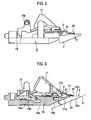
- Figs. 5 and 6 show a slide position of the movable blade 3 in a state where the cutting height of hair is set to the maximum.
- the cutting height adjusting mechanism described above is only one example, and any known cutting height adjusting mechanisms may be used only if the movable blade 3 can be slid in the projecting direction Y with respect to the stationary blade 2 in accordance with a user's operation.
- the comb projection 22 of the stationary blade 2 is provided at its lower surface with a skin-contact surface 22a that abuts against a skin.
- the comb projection 22 is also provided at its upper surface with a slide surface 22b with which the comb projection 32 of the movable blade 3 comes into slide contact.
- the main body 21 of the stationary blade 2 is provided at its lower surface with an opposed surface 21a opposed to a plane P including a skin-contact surface 22a.
- a rear end of the comb projection 22 is extended to a rear portion of the opposed surface 21a in the projecting direction (Y direction).
- the fixing plate 16 includes a bottom surface 16C and an inclined surface 16d.
- the inclined surface 16d is provided on a front portion of the fixing plate 16 in the projecting direction (Y direction) of the comb projections 22 and 32, and is inclined forward from a front end of the bottom surface 16C in the projecting direction (Y direction) of the comb projections 22 and 32. As shown in Fig. 6 , the inclined surface 16d is also opposed to the plane P including the skin-contact surface 22a.
- the opposed surface 21a of the main body 21 and the inclined surface 16d of the fixing plate 16 are substantially in parallel to the skin-contact surface 22a, and the opposed surface 2la and the inclined surface 16d are flush with each other.
- the opposed surface 2la of the main body 21 and the inclined surface 16d of the fixing plate 16 are located at high positions than the position of the comb projection 32 of the movable blade 3 in a state where the cutting height of hair is set to the maximum.
- a distance (shortest distance) between the plane P including the skin-contact surface 22a and the opposed surface 21a of the main body 21, and a distance (shortest distance) between the plane P including the skin-contact surface 22a and the inclined surface 16d of the fixing plate 16 are equal to or longer than a distance between the movable blade 3 and the comb projection 32 in a state where the plane P including the skin-contact surface 22a and the cutting height of hair become maximum.
- the opposed surface 21a and the inclined surface 16d may be at the same height as the position of the comb projection 32.
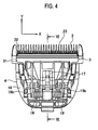
- smooth convex curve surfaces 24 (see Figs. 3 and 4 ) having a large radius of curvature are formed on both side ends of the stationary blade 2 in a direction (X direction) in which the comb projections 22 are arranged.
- the convex curve surfaces 24 are formed on substantially the entire surface except a surface opposed to the movable blade 3.
- the convex curve surface 24 is formed into a smooth convex shape in which a thickness of the convex curve surface 24 is reduced toward its end in the arrangement direction (X direction) so that slip between the stationary blade 2 and a skin becomes excellent, and roots to blade tip ends of the comb projections 22 and 32 in the projecting direction (Y direction) are continuously formed.
- the blade block 4 is placed such that the skin-contact surface 22a is below the blade block 4 and is oriented horizontally, and the opposed surface 21a of the main body 21 and the inclined surface 16d of the fixing plate 16 are located above the position of the comb projection 32 of the movable blade 3 in a state where the cutting height of hair is set excessively high.
- the hair-clipper is moved forward while bringing the skin-contact surface 22a into abutment against a skin from abutting against the opposed surface 21a and the inclined surface 16d. That is, since the cut hair is prevented from falling forward, it is possible to prevent cut before it is cut from being pushed forward, and the cutting height of hair can be more uniform.
- the opposed surface 21a of the main body 21 and the inclined surface 16d of the fixing plate 16 are located higher than the position of the comb projection 32 of the movable blade 3 in a state where the hair cutting height becomes the maximum. Therefore, it is possible to more equalize the hair cutting height in the hair cutting height in all adjustable range.
- the opposed surface 2la of the main body 21 of the stationary blade 2 is formed into a plane that is substantially in parallel to the plane P including the skin-contact surface 22a. Therefore, the structure of the main body 21 can be simplified, and the main body 21 can be machined easily. As a result, the machining amount of the stationary blade 2 can be reduced and cost thereof can be reduced.
- the rear portion of the comb projection 22 since the rear end of the comb projection 22 is extended to the rear portion of the opposed surface 21a in the projecting direction (Y direction), the rear portion of the comb projection 22 also functions as the comb, and a direction of hair after it is cut can be put in order.
- a hair-clipper according to a second embodiment of the present invention has the same constituent elements as those of the hair-clipper according to the first embodiment. Therefore, these constituent elements are designated with like reference numerals, and redundant explanations thereof will be omitted.
- the hair-clipper according to the second embodiment is different from the hair-clipper according to the first embodiment in that comb projections 22 of the stationary blade 2 correspond to the inclined surface 16d of a fixing plate 16A in terms of positions, and a rib 16e formed along the extending direction of the comb projection 22.
- Other structures of the second embodiment are basically the same as those of the first embodiment.
- the inclined surface 16d of the fixing plate 16A is provided with a rib 16e that corresponds to the comb projection 22 in terms of position and that is formed in the extending direction of the comb projection 22. Hair after it is cut is put in order also by the rib 16e. That is, the direction of the cut hair can be put in order more excellently.
- a hair-clipper according to a third embodiment of the present invention has the same constituent elements as those of the hair-clipper according to the first embodiment. Therefore, these constituent elements are designated with like reference numerals, and redundant explanations thereof will be omitted.
- the hair-clipper according to the third embodiment is different from that of the first embodiment in that an opposed surface 21aB formed on a lower surface of a main body 21B of the stationary blade 2, and an inclined surface 16dB formed in a front portion a bottom surface 16cB of a fixing plate 16B in the projecting direction (Y direction) are inclined rearward of the comb projections 22 and 32 in the projecting direction (Y direction) with respect to the plane P including the skin-contact surface 22a, and the opposed surface 21aB and the inclined surface 16dB are flush with each other.
- Other structures of the third embodiment are basically the same as those of the first embodiment.
- a distance between a front end of the opposed surface 21aB in the projecting direction (Y direction) which is the shortest distance between the plane P including the skin-contact surface 22a and the opposed surface 21aB of the main body 21B and the plane P including the skin-contact surface 22a is equal to or greater than a distance between the plane P including the skin-contact surface 22a and the comb projection 32 of the movable blade 3 in a state where the cutting height of hair is set to the maximum.
- a hair-clipper according to a fourth embodiment of the present invention has the same constituent elements as those of the hair-clipper according to the first embodiment. Therefore, these constituent elements are designated with like reference numerals, and redundant explanations thereof will be omitted.
- the hair-clipper according to the fourth embodiment is different from that of the first embodiment in that an inclined surface 16dC formed on a front portion of the bottom surface 16cC of the fixing plate 16C in the projecting direction (Y direction) is located higher than a position of the opposed surface 21a of the main body 21 in a state where the blade block 4 is placed such that the skin-contact surface 22a is blow the blade block 4 and horizontally.
- Other structures of the fourth embodiment are basically the same as those of the first embodiment.
- the opposed surface 21a and the inclined surface 16dC are formed into steps as shown in Fig. 9 .
- the opposed surface 21a and the inclined surface 16dC are formed substantially in parallel to the plane P including the skin-contact surface 22a.
- a distance (shortest distance) between the plane P including the skin-contact surface 22a and the opposed surface 2la of the main body 21 is equal to or greater than a distance between the plane P including the skin-contact surface 22a and the comb projection 32 of the movable blade 3 in a state where the hair cutting height is set to maximum.
- the opposed surface 21a and the inclined surface 16dC are substantially in parallel to the plane P including the skin-contact surface 22a in the fourth embodiment, the opposed surface 21a and the inclined surface 16dC may be inclined upward toward the rear portion of the comb projections 22 and 32 in the projecting direction (Y direction) with respect to the plane P including the skin-contact surface 22a as in the third embodiment.
- the first to fourth embodiments have exemplified the hair-clipper capable of adjusting the hair cutting height by sliding the movable blade to change the position of the movable blade with respect to the stationary blade.
- the hair-clipper it is also possible to use a hair-clipper in which the position of a movable blade with respect to a stationary blade is not changed, i.e., it is possible to use a hair-clipper that does not have the cutting height adjusting function.
- the inclined surface of the fixing plate can be provided with a rib.
- the fixing plate is mounted on the stationary blade using the fixing plate that is a separate member from the stationary blade. Therefore, the blade block can be reduced in weight by mounting a resin fixing plate on a metal stationary blade. Further, because the ratio of a metal portion in the entire blade block can be reduced, it is possible to reduce the usage amount of metal and a machining amount of the metal portion and also possible to reduce the cost.
Landscapes
- Life Sciences & Earth Sciences (AREA)
- Forests & Forestry (AREA)
- Engineering & Computer Science (AREA)
- Mechanical Engineering (AREA)
- Dry Shavers And Clippers (AREA)
Claims (4)
- Haarschneidemaschine mit:einem feststehenden Messer (2), das einen Hauptteil (21) hat, der mit einer Vielzahl von kammförmigen Vorsprüngen (22) versehen ist, die Klingen haben, die auf ihren beiden Seiten ausgebildet sind; undeinem beweglichen Messer (3), das einen Hauptteil (31) hat, der eine Vielzahl von kammförmigen Vorsprüngen (32) hat, die Klingen haben, die auf ihren beiden Seiten ausgebildet sind, und das in Kontakt mit dem feststehenden Messer (2) kommt, wobei das bewegliche Messer (3) in einer seitlichen Anordnungsrichtung (X-Richtung) hin und her bewegt und gleiten gelassen wird und die kammförmigen Vorsprünge (22) so in Bezug auf das feststehende Messer (2) angeordnet sind, dass sie Haare schneiden, die zwischen die Klingen der kammförmigen Vorsprünge (22) und der kammförmigen Vorsprünge (32) eingeführt werden, wobei die kammförmigen Vorsprünge (22) des feststehenden Messers (2), von einer Seite aus betrachtet, so verjüngt ausgebildet sind, dass sich ihre Dicke (t) entlang einer Vorsprungsrichtung (Y-Richtung) ändert,dadurch gekennzeichnet, dassdas bewegliche Messer (3) in der Vorsprungsrichtung (Y-Richtung) so gleiten kann, dass eine Schnitthöhe für die Haare eingestellt wird, wobei die kammförmigen Vorsprünge (22) des feststehenden Messers (2) eine ebene Hautkontaktfläche (22a), die an die Haut anstößt, und eine Gleitfläche (22b) haben, mit der die kammförmigen Vorsprünge (32) des beweglichen Messers (3) in Gleitkontakt kommen,der Hauptteil (21) des feststehenden Messers (2) eine Gegenfläche (21a) hat, die einer Ebene gegenüber liegt, in der die Hautkontaktfläche (22a) liegt, undder kürzeste Abstand zwischen der Gegenfläche (21a) und der Ebene, in der die Hautkontaktfläche (22a) liegt, gleich einem oder größer als ein Abstand zwischen der Ebene, in der die Hautkontaktfläche (22a) liegt, und dem kammförmigen Vorsprung (32) des beweglichen Messers (3) in dem Fall ist, dass die Schnitthöhe für die Haare maximal wird.
- Haarschneidemaschine nach Anspruch 1, dadurch gekennzeichnet, dass die Gegenfläche (21a) des Hauptteils (21) des feststehenden Messers (2) im Wesentlichen parallel zu der Ebene ist, in der die Hautkontaktfläche (22a) liegt.
- Haarschneidemaschine nach Anspruch 1, dadurch gekennzeichnet, dass die Gegenfläche (21a) des Hauptteils (21) des feststehenden Messers (2) nach oben und hinten in einer Vorsprungsrichtung des kammförmigen Vorsprungs (22, 32) in Bezug auf die Ebene geneigt ist, in der die Hautkontaktfläche (22a) liegt.
- Haarschneidemaschine nach einem der Ansprüche 1 bis 3, dadurch gekennzeichnet, dass
eine Befestigungsplatte (16), an der der Hauptteil (21) des feststehenden Messers (2) befestigt ist, in einem hinteren Teil des kammförmigen Vorsprungs (22) des Hauptteils (21) des feststehenden Messers (2) in der Vorsprungsrichtung vorgesehen ist,
die Befestigungsplatte (16) eine geneigte Fläche (16d) hat, die von dem vorderen Ende einer Unterseite (16c) der Befestigungsplatte (16) aus geneigt ist und die in dem vorderen Teil der Befestigungsplatte (16) der Ebene (P) gegenüber liegt, in der die Hautkontaktfläche (22a) liegt, und
der kürzeste Abstand zwischen der geneigten Fläche (16d) und der Ebene, in der die Hautkontaktfläche (22a) liegt, gleich einem oder größer als ein Abstand zwischen der Ebene, in der die Hautkontaktfläche (22a) liegt, und dem kammförmigen Vorsprung (32) des beweglichen Messers (3) in dem Fall ist, dass die Schnitthöhe für die Haare maximal wird.
Applications Claiming Priority (1)
| Application Number | Priority Date | Filing Date | Title |
|---|---|---|---|
| JP2007220675A JP4730353B2 (ja) | 2007-08-28 | 2007-08-28 | バリカン |
Publications (2)
| Publication Number | Publication Date |
|---|---|
| EP2030743A1 EP2030743A1 (de) | 2009-03-04 |
| EP2030743B1 true EP2030743B1 (de) | 2010-11-17 |
Family
ID=39939896
Family Applications (1)
| Application Number | Title | Priority Date | Filing Date |
|---|---|---|---|
| EP08015012A Active EP2030743B1 (de) | 2007-08-28 | 2008-08-25 | Haarschneidemaschine |
Country Status (8)
| Country | Link |
|---|---|
| US (1) | US8713802B2 (de) |
| EP (1) | EP2030743B1 (de) |
| JP (1) | JP4730353B2 (de) |
| KR (2) | KR101081133B1 (de) |
| CN (1) | CN101417432B (de) |
| AT (1) | ATE488338T1 (de) |
| DE (1) | DE602008003494D1 (de) |
| RU (1) | RU2385800C1 (de) |
Families Citing this family (33)
| Publication number | Priority date | Publication date | Assignee | Title |
|---|---|---|---|---|
| JP4251213B2 (ja) * | 2006-12-11 | 2009-04-08 | パナソニック電工株式会社 | ヘアークリッパーの刃ブロック |
| US8806757B2 (en) * | 2010-04-30 | 2014-08-19 | Wahl Clipper Corporation | Arched hair clipper blade guide |
| US8561300B2 (en) * | 2010-06-16 | 2013-10-22 | The Gillette Company | Combination shaving and trimming device |
| JP5238051B2 (ja) * | 2011-03-22 | 2013-07-17 | パナソニック株式会社 | トリマー刃 |
| CN103182716A (zh) * | 2011-12-27 | 2013-07-03 | 温州市百特电器有限公司 | 一种理发剪刀头 |
| DK177610B1 (en) * | 2012-05-01 | 2013-12-02 | Klaus Lauritsen Holding Aps | Programmable hair trimming system |
| US9242385B2 (en) * | 2013-05-16 | 2016-01-26 | Wahl Clipper Corporation | Drive assembly for hair trimmers |
| US9144911B2 (en) * | 2013-05-31 | 2015-09-29 | Wahl Clipper Corporation | Linear drive system for hair clippers |
| CN105189056B (zh) * | 2013-10-31 | 2017-05-24 | 皇家飞利浦有限公司 | 可编程头发修剪系统 |
| RU189106U1 (ru) * | 2013-11-05 | 2019-05-13 | Конинклейке Филипс Н.В. | Программируемая система для стрижки волос |
| JP6563917B2 (ja) | 2013-11-06 | 2019-08-21 | コーニンクレッカ フィリップス エヌ ヴェKoninklijke Philips N.V. | 身体部位を処置するためのシステム及び方法 |
| RU2680324C2 (ru) * | 2014-04-18 | 2019-02-19 | Конинклейке Филипс Н.В. | Ножевой блок, устройство для срезания волос и соответствующий способ изготовления |
| US9713877B2 (en) | 2014-11-12 | 2017-07-25 | Medline Industries, Inc. | Clipper head with drag reduction |
| USD779123S1 (en) | 2014-11-12 | 2017-02-14 | Medline Industries, Inc. | Clipper head |
| US9545729B2 (en) * | 2015-03-26 | 2017-01-17 | Wahl Clipper Corporation | Hair trimmer blade set with adjustable blades |
| CN105058439A (zh) * | 2015-08-08 | 2015-11-18 | 海宁市三鑫剃须刀剪有限公司 | 一种新型理发剪刀头 |
| USD794871S1 (en) | 2016-01-15 | 2017-08-15 | Medline Industries, Inc. | Clipper |
| USD795497S1 (en) | 2016-01-15 | 2017-08-22 | Medline Industries, Inc. | Clipper |
| WO2017153482A1 (en) * | 2016-03-08 | 2017-09-14 | Koninklijke Philips N.V. | Blade set manufacturing method, blade set and hair cutting appliance |
| RU2740494C2 (ru) | 2016-04-06 | 2021-01-14 | Конинклейке Филипс Н.В. | Способ изготовления набора лезвий, набор лезвий и устройство для стрижки волос |
| USD802216S1 (en) | 2016-06-10 | 2017-11-07 | Medline Industries, Inc. | Clipper head |
| USD802214S1 (en) | 2016-06-10 | 2017-11-07 | Medline Industries, Inc. | Clipper head |
| USD802215S1 (en) | 2016-06-10 | 2017-11-07 | Medline Industries, Inc. | Clipper head |
| USD802217S1 (en) | 2016-06-10 | 2017-11-07 | Medline Industries, Inc. | Clipper head |
| EP3372357A1 (de) * | 2017-03-10 | 2018-09-12 | Koninklijke Philips N.V. | Handhaltbare körperpflegevorrichtung und verfahren zur bestimmung einer position und/oder einer ausrichtung einer handhaltbaren persönlichen vorrichtung in bezug auf eine person |
| CN110181565A (zh) * | 2019-06-26 | 2019-08-30 | 温州市日电电器有限公司 | 一种剃须刀刀头及其贴合面挡板 |
| CN110561504B (zh) * | 2019-09-25 | 2024-07-30 | 浙江美森电器有限公司 | 一种减震式剃须刀头 |
| USD965896S1 (en) * | 2020-11-09 | 2022-10-04 | XiaoYan Chen | Hair clipper |
| USD1006326S1 (en) | 2021-03-26 | 2023-11-28 | Manscaped, Llc | Body of an electric groomer |
| EP4112250B1 (de) * | 2021-06-28 | 2025-07-16 | Braun GmbH | Haarschneidekit |
| USD1099427S1 (en) | 2021-09-14 | 2025-10-21 | Wahl Clipper Corporation | Hair clipper bladeset |
| WO2023043629A1 (en) | 2021-09-14 | 2023-03-23 | Wahl Clipper Corporation | Hair clipper bladeset with variable rake angle array tooth geometry |
| JP2025005894A (ja) * | 2023-06-28 | 2025-01-17 | パナソニックIpマネジメント株式会社 | 切断装置 |
Family Cites Families (39)
| Publication number | Priority date | Publication date | Assignee | Title |
|---|---|---|---|---|
| DE126789C (de) * | ||||
| FR643305A (fr) | 1927-11-03 | 1928-09-14 | Perfectionnements aux tondeuses | |
| US2641833A (en) | 1951-05-10 | 1953-06-16 | Waldo H Need | Hair clipper with improved reciprocable cutter blade |
| GB781014A (en) | 1954-03-24 | 1957-08-14 | Richard Lawrence Hudson | Improvements in clipper combs |
| US3032875A (en) | 1959-07-27 | 1962-05-08 | Ralph W Gwynne | Hair trimmer head |
| US3100342A (en) | 1960-10-13 | 1963-08-13 | Schmidt Gerhard R | Hair clipper |
| US3279056A (en) * | 1964-10-28 | 1966-10-18 | Andis Clipper Co | Double-edge combination dry shaver and finishing hair clipper with adjustable head |
| AT272889B (de) | 1966-04-06 | 1969-07-25 | Kurt Heyek | Scherkopf für Trockenrasierapparate |
| NL165967C (nl) * | 1973-05-03 | 1981-06-15 | Liedtke Christa | Haarsnijtoestel. |
| DD126789A1 (de) | 1976-07-27 | 1977-08-10 | ||
| JPS5320674U (de) * | 1976-07-30 | 1978-02-21 | ||
| JPS5320674A (en) | 1976-08-10 | 1978-02-25 | Kubota Ltd | Incinerator of trash |
| JPS5361470A (en) * | 1976-11-10 | 1978-06-01 | Hitachi Maxell Ltd | Electric clipper |
| JPS5389551A (en) * | 1977-01-13 | 1978-08-07 | Matsushita Electric Works Ltd | Hair clipper blade set |
| SU859144A1 (ru) | 1979-06-25 | 1981-08-30 | Предприятие П/Я Г-4651 | Режуща головка электробритвы |
| JPH0292389A (ja) * | 1988-09-27 | 1990-04-03 | Matsushita Electric Works Ltd | ヘアカッター |
| US5367772A (en) * | 1992-05-26 | 1994-11-29 | Matsushita Electric Works, Ltd. | Hair clipper |
| JP3512880B2 (ja) | 1994-10-14 | 2004-03-31 | 日本水産株式会社 | ソース味付きたこ焼き |
| US6079103A (en) * | 1998-01-09 | 2000-06-27 | Wahl Clipper Corporation | Adjustable attachment comb |
| JP3814816B2 (ja) | 1998-09-30 | 2006-08-30 | マツダ株式会社 | ハイブリッド自動車 |
| JP4099999B2 (ja) | 2002-01-30 | 2008-06-11 | 松下電工株式会社 | ヘアカッター |
| US6901664B2 (en) * | 2002-07-18 | 2005-06-07 | Wahl Clipper Corporation | Hair clipper and seal |
| JP2004254757A (ja) | 2003-02-24 | 2004-09-16 | Izumi Products Co | 往復動式電気かみそり |
| KR200316122Y1 (ko) | 2003-03-06 | 2003-06-12 | 오태준 | 전기이발기 에칭날 |
| JP2004267417A (ja) | 2003-03-07 | 2004-09-30 | Izumi Products Co | 往復動式電気かみそり |
| US20040200077A1 (en) * | 2003-04-14 | 2004-10-14 | Shu-Sian Liao | Blade module of electric clipper |
| JP4552646B2 (ja) | 2004-12-16 | 2010-09-29 | パナソニック電工株式会社 | 除毛装置 |
| JP4604846B2 (ja) | 2005-05-31 | 2011-01-05 | パナソニック電工株式会社 | 体毛処理器具 |
| JP5074679B2 (ja) | 2005-08-26 | 2012-11-14 | パナソニック株式会社 | バリカン |
| US7234242B2 (en) | 2005-11-14 | 2007-06-26 | Woody Yao | Adjustable apparatus for hair clipper |
| JP5320674B2 (ja) | 2006-01-27 | 2013-10-23 | 三菱瓦斯化学株式会社 | エポキシ樹脂硬化剤及びエポキシ樹脂組成物 |
| JP4127299B2 (ja) | 2006-06-16 | 2008-07-30 | 松下電工株式会社 | ヘアークリッパー |
| US7918029B2 (en) * | 2006-07-07 | 2011-04-05 | Wahl Clipper Corporation | Attachment comb for a hair clipper |
| US7703210B2 (en) * | 2007-12-11 | 2010-04-27 | Specialife Industries Limited | Blade driving assembly for an adjustable hair clipper |
| JP2010004992A (ja) * | 2008-06-25 | 2010-01-14 | Panasonic Electric Works Co Ltd | バリカン刃、及び電動バリカン |
| US20110173818A1 (en) * | 2008-09-17 | 2011-07-21 | Sean Lacov | Clipper/trimmer blade set |
| JP5361470B2 (ja) | 2009-03-16 | 2013-12-04 | キヤノン株式会社 | 情報処理装置及びその制御方法 |
| JP5389551B2 (ja) | 2009-07-09 | 2014-01-15 | 株式会社サービス・マーチャンダイジング・システムズ | 歯ブラシ |
| US20110061243A1 (en) * | 2009-09-15 | 2011-03-17 | Adriaan Smit | Attachment comb for hair trimmer |
-
2007
- 2007-08-28 JP JP2007220675A patent/JP4730353B2/ja not_active Expired - Fee Related
-
2008
- 2008-08-21 US US12/195,728 patent/US8713802B2/en active Active
- 2008-08-25 KR KR1020080082688A patent/KR101081133B1/ko active Active
- 2008-08-25 DE DE602008003494T patent/DE602008003494D1/de active Active
- 2008-08-25 EP EP08015012A patent/EP2030743B1/de active Active
- 2008-08-25 AT AT08015012T patent/ATE488338T1/de not_active IP Right Cessation
- 2008-08-27 RU RU2008135061/02A patent/RU2385800C1/ru not_active IP Right Cessation
- 2008-08-28 CN CN2008101842548A patent/CN101417432B/zh active Active
-
2011
- 2011-07-25 KR KR1020110073524A patent/KR101174609B1/ko active Active
Also Published As
| Publication number | Publication date |
|---|---|
| KR101081133B1 (ko) | 2011-11-07 |
| KR101174609B1 (ko) | 2012-08-16 |
| RU2008135061A (ru) | 2010-03-10 |
| JP2009050496A (ja) | 2009-03-12 |
| US8713802B2 (en) | 2014-05-06 |
| KR20110099076A (ko) | 2011-09-06 |
| ATE488338T1 (de) | 2010-12-15 |
| CN101417432B (zh) | 2011-03-09 |
| RU2385800C1 (ru) | 2010-04-10 |
| DE602008003494D1 (de) | 2010-12-30 |
| US20090056143A1 (en) | 2009-03-05 |
| JP4730353B2 (ja) | 2011-07-20 |
| EP2030743A1 (de) | 2009-03-04 |
| CN101417432A (zh) | 2009-04-29 |
| KR20090023145A (ko) | 2009-03-04 |
Similar Documents
| Publication | Publication Date | Title |
|---|---|---|
| US8713802B2 (en) | Hair-clipper | |
| US20080052915A1 (en) | Hair clipper | |
| EP1757413B1 (de) | Haarschneidegerät | |
| US20080282550A1 (en) | Blade assembly | |
| EP2771148B1 (de) | Hobelmaschinenzubehörwerkzeug für ein schwingendes elektrisches werkzeug | |
| EP2492066B1 (de) | Elektrischer Rasierapparat | |
| CN110653417B (zh) | 便携式带锯 | |
| JPH04117986A (ja) | 電気バリカン | |
| JP6395303B2 (ja) | 電気かみそり | |
| US20130091709A1 (en) | Hair remover | |
| US20120272533A1 (en) | Hair clipper | |
| US20250360639A1 (en) | Attachment for cutting device and cutting device to which attachment is attached | |
| US20250001630A1 (en) | Cutting device | |
| JP5258864B2 (ja) | バリカン | |
| JP2005304627A (ja) | ヘアカッター | |
| JP4888882B2 (ja) | バリカン | |
| CN117505983A (zh) | 斜锯 | |
| KR200381510Y1 (ko) | 전기바리캉의 칼날 조절장치 | |
| JPS6110623Y2 (de) | ||
| JP2017213114A (ja) | 電気かみそり | |
| JP2025040306A (ja) | ジグソー | |
| JPH0720216U (ja) | 電動丸鋸 | |
| JPH0320275B2 (de) | ||
| JP2005198898A (ja) | 長柄かみそり |
Legal Events
| Date | Code | Title | Description |
|---|---|---|---|
| PUAI | Public reference made under article 153(3) epc to a published international application that has entered the european phase |
Free format text: ORIGINAL CODE: 0009012 |
|
| AK | Designated contracting states |
Kind code of ref document: A1 Designated state(s): AT BE BG CH CY CZ DE DK EE ES FI FR GB GR HR HU IE IS IT LI LT LU LV MC MT NL NO PL PT RO SE SI SK TR |
|
| AX | Request for extension of the european patent |
Extension state: AL BA MK RS |
|
| AKX | Designation fees paid | ||
| 17P | Request for examination filed |
Effective date: 20090901 |
|
| RBV | Designated contracting states (corrected) |
Designated state(s): AT BE BG CH CY CZ DE DK EE ES FI FR GB GR HR HU IE IS IT LI LT LU LV MC MT NL NO PL PT RO SE SI SK TR |
|
| GRAP | Despatch of communication of intention to grant a patent |
Free format text: ORIGINAL CODE: EPIDOSNIGR1 |
|
| RIN1 | Information on inventor provided before grant (corrected) |
Inventor name: INABA, JIRO Inventor name: FUKUTANI, MAKOTO Inventor name: IKUTA, TOSHIO |
|
| GRAS | Grant fee paid |
Free format text: ORIGINAL CODE: EPIDOSNIGR3 |
|
| GRAA | (expected) grant |
Free format text: ORIGINAL CODE: 0009210 |
|
| AK | Designated contracting states |
Kind code of ref document: B1 Designated state(s): AT BE BG CH CY CZ DE DK EE ES FI FR GB GR HR HU IE IS IT LI LT LU LV MC MT NL NO PL PT RO SE SI SK TR |
|
| REG | Reference to a national code |
Ref country code: GB Ref legal event code: FG4D |
|
| REG | Reference to a national code |
Ref country code: CH Ref legal event code: EP |
|
| REG | Reference to a national code |
Ref country code: IE Ref legal event code: FG4D |
|
| REF | Corresponds to: |
Ref document number: 602008003494 Country of ref document: DE Date of ref document: 20101230 Kind code of ref document: P |
|
| REG | Reference to a national code |
Ref country code: NL Ref legal event code: VDEP Effective date: 20101117 |
|
| LTIE | Lt: invalidation of european patent or patent extension |
Effective date: 20101117 |
|
| PG25 | Lapsed in a contracting state [announced via postgrant information from national office to epo] |
Ref country code: NO Free format text: LAPSE BECAUSE OF FAILURE TO SUBMIT A TRANSLATION OF THE DESCRIPTION OR TO PAY THE FEE WITHIN THE PRESCRIBED TIME-LIMIT Effective date: 20110217 Ref country code: LT Free format text: LAPSE BECAUSE OF FAILURE TO SUBMIT A TRANSLATION OF THE DESCRIPTION OR TO PAY THE FEE WITHIN THE PRESCRIBED TIME-LIMIT Effective date: 20101117 |
|
| PG25 | Lapsed in a contracting state [announced via postgrant information from national office to epo] |
Ref country code: BG Free format text: LAPSE BECAUSE OF FAILURE TO SUBMIT A TRANSLATION OF THE DESCRIPTION OR TO PAY THE FEE WITHIN THE PRESCRIBED TIME-LIMIT Effective date: 20110217 Ref country code: IS Free format text: LAPSE BECAUSE OF FAILURE TO SUBMIT A TRANSLATION OF THE DESCRIPTION OR TO PAY THE FEE WITHIN THE PRESCRIBED TIME-LIMIT Effective date: 20110317 Ref country code: SE Free format text: LAPSE BECAUSE OF FAILURE TO SUBMIT A TRANSLATION OF THE DESCRIPTION OR TO PAY THE FEE WITHIN THE PRESCRIBED TIME-LIMIT Effective date: 20101117 Ref country code: LV Free format text: LAPSE BECAUSE OF FAILURE TO SUBMIT A TRANSLATION OF THE DESCRIPTION OR TO PAY THE FEE WITHIN THE PRESCRIBED TIME-LIMIT Effective date: 20101117 Ref country code: PT Free format text: LAPSE BECAUSE OF FAILURE TO SUBMIT A TRANSLATION OF THE DESCRIPTION OR TO PAY THE FEE WITHIN THE PRESCRIBED TIME-LIMIT Effective date: 20110317 Ref country code: AT Free format text: LAPSE BECAUSE OF FAILURE TO SUBMIT A TRANSLATION OF THE DESCRIPTION OR TO PAY THE FEE WITHIN THE PRESCRIBED TIME-LIMIT Effective date: 20101117 Ref country code: CY Free format text: LAPSE BECAUSE OF FAILURE TO SUBMIT A TRANSLATION OF THE DESCRIPTION OR TO PAY THE FEE WITHIN THE PRESCRIBED TIME-LIMIT Effective date: 20101117 Ref country code: HR Free format text: LAPSE BECAUSE OF FAILURE TO SUBMIT A TRANSLATION OF THE DESCRIPTION OR TO PAY THE FEE WITHIN THE PRESCRIBED TIME-LIMIT Effective date: 20101117 Ref country code: FI Free format text: LAPSE BECAUSE OF FAILURE TO SUBMIT A TRANSLATION OF THE DESCRIPTION OR TO PAY THE FEE WITHIN THE PRESCRIBED TIME-LIMIT Effective date: 20101117 Ref country code: SI Free format text: LAPSE BECAUSE OF FAILURE TO SUBMIT A TRANSLATION OF THE DESCRIPTION OR TO PAY THE FEE WITHIN THE PRESCRIBED TIME-LIMIT Effective date: 20101117 Ref country code: NL Free format text: LAPSE BECAUSE OF FAILURE TO SUBMIT A TRANSLATION OF THE DESCRIPTION OR TO PAY THE FEE WITHIN THE PRESCRIBED TIME-LIMIT Effective date: 20101117 |
|
| PG25 | Lapsed in a contracting state [announced via postgrant information from national office to epo] |
Ref country code: GR Free format text: LAPSE BECAUSE OF FAILURE TO SUBMIT A TRANSLATION OF THE DESCRIPTION OR TO PAY THE FEE WITHIN THE PRESCRIBED TIME-LIMIT Effective date: 20110218 |
|
| PG25 | Lapsed in a contracting state [announced via postgrant information from national office to epo] |
Ref country code: BE Free format text: LAPSE BECAUSE OF FAILURE TO SUBMIT A TRANSLATION OF THE DESCRIPTION OR TO PAY THE FEE WITHIN THE PRESCRIBED TIME-LIMIT Effective date: 20101117 Ref country code: CZ Free format text: LAPSE BECAUSE OF FAILURE TO SUBMIT A TRANSLATION OF THE DESCRIPTION OR TO PAY THE FEE WITHIN THE PRESCRIBED TIME-LIMIT Effective date: 20101117 Ref country code: EE Free format text: LAPSE BECAUSE OF FAILURE TO SUBMIT A TRANSLATION OF THE DESCRIPTION OR TO PAY THE FEE WITHIN THE PRESCRIBED TIME-LIMIT Effective date: 20101117 Ref country code: ES Free format text: LAPSE BECAUSE OF FAILURE TO SUBMIT A TRANSLATION OF THE DESCRIPTION OR TO PAY THE FEE WITHIN THE PRESCRIBED TIME-LIMIT Effective date: 20110228 |
|
| PG25 | Lapsed in a contracting state [announced via postgrant information from national office to epo] |
Ref country code: RO Free format text: LAPSE BECAUSE OF FAILURE TO SUBMIT A TRANSLATION OF THE DESCRIPTION OR TO PAY THE FEE WITHIN THE PRESCRIBED TIME-LIMIT Effective date: 20101117 Ref country code: SK Free format text: LAPSE BECAUSE OF FAILURE TO SUBMIT A TRANSLATION OF THE DESCRIPTION OR TO PAY THE FEE WITHIN THE PRESCRIBED TIME-LIMIT Effective date: 20101117 Ref country code: DK Free format text: LAPSE BECAUSE OF FAILURE TO SUBMIT A TRANSLATION OF THE DESCRIPTION OR TO PAY THE FEE WITHIN THE PRESCRIBED TIME-LIMIT Effective date: 20101117 Ref country code: PL Free format text: LAPSE BECAUSE OF FAILURE TO SUBMIT A TRANSLATION OF THE DESCRIPTION OR TO PAY THE FEE WITHIN THE PRESCRIBED TIME-LIMIT Effective date: 20101117 |
|
| PLBE | No opposition filed within time limit |
Free format text: ORIGINAL CODE: 0009261 |
|
| STAA | Information on the status of an ep patent application or granted ep patent |
Free format text: STATUS: NO OPPOSITION FILED WITHIN TIME LIMIT |
|
| 26N | No opposition filed |
Effective date: 20110818 |
|
| REG | Reference to a national code |
Ref country code: DE Ref legal event code: R097 Ref document number: 602008003494 Country of ref document: DE Effective date: 20110818 |
|
| PG25 | Lapsed in a contracting state [announced via postgrant information from national office to epo] |
Ref country code: MT Free format text: LAPSE BECAUSE OF FAILURE TO SUBMIT A TRANSLATION OF THE DESCRIPTION OR TO PAY THE FEE WITHIN THE PRESCRIBED TIME-LIMIT Effective date: 20101117 |
|
| PG25 | Lapsed in a contracting state [announced via postgrant information from national office to epo] |
Ref country code: MC Free format text: LAPSE BECAUSE OF NON-PAYMENT OF DUE FEES Effective date: 20110831 |
|
| REG | Reference to a national code |
Ref country code: IE Ref legal event code: MM4A |
|
| PG25 | Lapsed in a contracting state [announced via postgrant information from national office to epo] |
Ref country code: IE Free format text: LAPSE BECAUSE OF NON-PAYMENT OF DUE FEES Effective date: 20110825 |
|
| REG | Reference to a national code |
Ref country code: CH Ref legal event code: PL |
|
| GBPC | Gb: european patent ceased through non-payment of renewal fee |
Effective date: 20120825 |
|
| PG25 | Lapsed in a contracting state [announced via postgrant information from national office to epo] |
Ref country code: CH Free format text: LAPSE BECAUSE OF NON-PAYMENT OF DUE FEES Effective date: 20120831 Ref country code: LI Free format text: LAPSE BECAUSE OF NON-PAYMENT OF DUE FEES Effective date: 20120831 |
|
| PG25 | Lapsed in a contracting state [announced via postgrant information from national office to epo] |
Ref country code: LU Free format text: LAPSE BECAUSE OF NON-PAYMENT OF DUE FEES Effective date: 20110825 |
|
| PG25 | Lapsed in a contracting state [announced via postgrant information from national office to epo] |
Ref country code: GB Free format text: LAPSE BECAUSE OF NON-PAYMENT OF DUE FEES Effective date: 20120825 |
|
| PG25 | Lapsed in a contracting state [announced via postgrant information from national office to epo] |
Ref country code: TR Free format text: LAPSE BECAUSE OF FAILURE TO SUBMIT A TRANSLATION OF THE DESCRIPTION OR TO PAY THE FEE WITHIN THE PRESCRIBED TIME-LIMIT Effective date: 20101117 |
|
| PG25 | Lapsed in a contracting state [announced via postgrant information from national office to epo] |
Ref country code: HU Free format text: LAPSE BECAUSE OF FAILURE TO SUBMIT A TRANSLATION OF THE DESCRIPTION OR TO PAY THE FEE WITHIN THE PRESCRIBED TIME-LIMIT Effective date: 20101117 |
|
| PGFP | Annual fee paid to national office [announced via postgrant information from national office to epo] |
Ref country code: FR Payment date: 20130808 Year of fee payment: 6 |
|
| PGFP | Annual fee paid to national office [announced via postgrant information from national office to epo] |
Ref country code: IT Payment date: 20130809 Year of fee payment: 6 |
|
| PG25 | Lapsed in a contracting state [announced via postgrant information from national office to epo] |
Ref country code: IT Free format text: LAPSE BECAUSE OF NON-PAYMENT OF DUE FEES Effective date: 20140825 |
|
| REG | Reference to a national code |
Ref country code: FR Ref legal event code: ST Effective date: 20150430 |
|
| PG25 | Lapsed in a contracting state [announced via postgrant information from national office to epo] |
Ref country code: FR Free format text: LAPSE BECAUSE OF NON-PAYMENT OF DUE FEES Effective date: 20140901 |
|
| PGFP | Annual fee paid to national office [announced via postgrant information from national office to epo] |
Ref country code: DE Payment date: 20250702 Year of fee payment: 18 |