EP2030764B1 - Verfahren und Vorrichtung zum Herstellen von Gegenständen mit strukturierten Oberflächen - Google Patents
Verfahren und Vorrichtung zum Herstellen von Gegenständen mit strukturierten Oberflächen Download PDFInfo
- Publication number
- EP2030764B1 EP2030764B1 EP08163308A EP08163308A EP2030764B1 EP 2030764 B1 EP2030764 B1 EP 2030764B1 EP 08163308 A EP08163308 A EP 08163308A EP 08163308 A EP08163308 A EP 08163308A EP 2030764 B1 EP2030764 B1 EP 2030764B1
- Authority
- EP
- European Patent Office
- Prior art keywords
- mold
- tool
- pressurizer
- charge
- contoured
- Prior art date
- Legal status (The legal status is an assumption and is not a legal conclusion. Google has not performed a legal analysis and makes no representation as to the accuracy of the status listed.)
- Active
Links
Images




Classifications
-
- B—PERFORMING OPERATIONS; TRANSPORTING
- B29—WORKING OF PLASTICS; WORKING OF SUBSTANCES IN A PLASTIC STATE IN GENERAL
- B29C—SHAPING OR JOINING OF PLASTICS; SHAPING OF MATERIAL IN A PLASTIC STATE, NOT OTHERWISE PROVIDED FOR; AFTER-TREATMENT OF THE SHAPED PRODUCTS, e.g. REPAIRING
- B29C70/00—Shaping composites, i.e. plastics material comprising reinforcements, fillers or preformed parts, e.g. inserts
- B29C70/04—Shaping composites, i.e. plastics material comprising reinforcements, fillers or preformed parts, e.g. inserts comprising reinforcements only, e.g. self-reinforcing plastics
- B29C70/28—Shaping operations therefor
- B29C70/40—Shaping or impregnating by compression not applied
- B29C70/42—Shaping or impregnating by compression not applied for producing articles of definite length, i.e. discrete articles
- B29C70/46—Shaping or impregnating by compression not applied for producing articles of definite length, i.e. discrete articles using matched moulds, e.g. for deforming sheet moulding compounds [SMC] or prepregs
-
- B—PERFORMING OPERATIONS; TRANSPORTING
- B29—WORKING OF PLASTICS; WORKING OF SUBSTANCES IN A PLASTIC STATE IN GENERAL
- B29C—SHAPING OR JOINING OF PLASTICS; SHAPING OF MATERIAL IN A PLASTIC STATE, NOT OTHERWISE PROVIDED FOR; AFTER-TREATMENT OF THE SHAPED PRODUCTS, e.g. REPAIRING
- B29C33/00—Moulds or cores; Details thereof or accessories therefor
- B29C33/42—Moulds or cores; Details thereof or accessories therefor characterised by the shape of the moulding surface, e.g. ribs or grooves
- B29C33/424—Moulding surfaces provided with means for marking or patterning
-
- B—PERFORMING OPERATIONS; TRANSPORTING
- B29—WORKING OF PLASTICS; WORKING OF SUBSTANCES IN A PLASTIC STATE IN GENERAL
- B29C—SHAPING OR JOINING OF PLASTICS; SHAPING OF MATERIAL IN A PLASTIC STATE, NOT OTHERWISE PROVIDED FOR; AFTER-TREATMENT OF THE SHAPED PRODUCTS, e.g. REPAIRING
- B29C33/00—Moulds or cores; Details thereof or accessories therefor
- B29C33/44—Moulds or cores; Details thereof or accessories therefor with means for, or specially constructed to facilitate, the removal of articles, e.g. of undercut articles
- B29C33/48—Moulds or cores; Details thereof or accessories therefor with means for, or specially constructed to facilitate, the removal of articles, e.g. of undercut articles with means for collapsing or disassembling
- B29C33/50—Moulds or cores; Details thereof or accessories therefor with means for, or specially constructed to facilitate, the removal of articles, e.g. of undercut articles with means for collapsing or disassembling elastic or flexible
-
- B—PERFORMING OPERATIONS; TRANSPORTING
- B29—WORKING OF PLASTICS; WORKING OF SUBSTANCES IN A PLASTIC STATE IN GENERAL
- B29C—SHAPING OR JOINING OF PLASTICS; SHAPING OF MATERIAL IN A PLASTIC STATE, NOT OTHERWISE PROVIDED FOR; AFTER-TREATMENT OF THE SHAPED PRODUCTS, e.g. REPAIRING
- B29C43/00—Compression moulding, i.e. applying external pressure to flow the moulding material; Apparatus therefor
- B29C43/02—Compression moulding, i.e. applying external pressure to flow the moulding material; Apparatus therefor of articles of definite length, i.e. discrete articles
- B29C43/14—Compression moulding, i.e. applying external pressure to flow the moulding material; Apparatus therefor of articles of definite length, i.e. discrete articles in several steps
- B29C43/146—Compression moulding, i.e. applying external pressure to flow the moulding material; Apparatus therefor of articles of definite length, i.e. discrete articles in several steps for making multilayered articles
-
- B—PERFORMING OPERATIONS; TRANSPORTING
- B29—WORKING OF PLASTICS; WORKING OF SUBSTANCES IN A PLASTIC STATE IN GENERAL
- B29C—SHAPING OR JOINING OF PLASTICS; SHAPING OF MATERIAL IN A PLASTIC STATE, NOT OTHERWISE PROVIDED FOR; AFTER-TREATMENT OF THE SHAPED PRODUCTS, e.g. REPAIRING
- B29C43/00—Compression moulding, i.e. applying external pressure to flow the moulding material; Apparatus therefor
- B29C43/02—Compression moulding, i.e. applying external pressure to flow the moulding material; Apparatus therefor of articles of definite length, i.e. discrete articles
- B29C43/18—Compression moulding, i.e. applying external pressure to flow the moulding material; Apparatus therefor of articles of definite length, i.e. discrete articles incorporating preformed parts or layers, e.g. compression moulding around inserts or for coating articles
- B29C43/183—Compression moulding, i.e. applying external pressure to flow the moulding material; Apparatus therefor of articles of definite length, i.e. discrete articles incorporating preformed parts or layers, e.g. compression moulding around inserts or for coating articles the preformed layer being a lining, e.g. shaped in the mould before compression moulding, or a preformed shell adapted to the shape of the mould
-
- B—PERFORMING OPERATIONS; TRANSPORTING
- B29—WORKING OF PLASTICS; WORKING OF SUBSTANCES IN A PLASTIC STATE IN GENERAL
- B29C—SHAPING OR JOINING OF PLASTICS; SHAPING OF MATERIAL IN A PLASTIC STATE, NOT OTHERWISE PROVIDED FOR; AFTER-TREATMENT OF THE SHAPED PRODUCTS, e.g. REPAIRING
- B29C43/00—Compression moulding, i.e. applying external pressure to flow the moulding material; Apparatus therefor
- B29C43/32—Component parts, details or accessories; Auxiliary operations
- B29C43/36—Moulds for making articles of definite length, i.e. discrete articles
- B29C43/3642—Bags, bleeder sheets or cauls for isostatic pressing
-
- B—PERFORMING OPERATIONS; TRANSPORTING
- B29—WORKING OF PLASTICS; WORKING OF SUBSTANCES IN A PLASTIC STATE IN GENERAL
- B29C—SHAPING OR JOINING OF PLASTICS; SHAPING OF MATERIAL IN A PLASTIC STATE, NOT OTHERWISE PROVIDED FOR; AFTER-TREATMENT OF THE SHAPED PRODUCTS, e.g. REPAIRING
- B29C70/00—Shaping composites, i.e. plastics material comprising reinforcements, fillers or preformed parts, e.g. inserts
- B29C70/04—Shaping composites, i.e. plastics material comprising reinforcements, fillers or preformed parts, e.g. inserts comprising reinforcements only, e.g. self-reinforcing plastics
- B29C70/28—Shaping operations therefor
- B29C70/40—Shaping or impregnating by compression not applied
- B29C70/42—Shaping or impregnating by compression not applied for producing articles of definite length, i.e. discrete articles
- B29C70/44—Shaping or impregnating by compression not applied for producing articles of definite length, i.e. discrete articles using isostatic pressure, e.g. pressure difference-moulding, vacuum bag-moulding, autoclave-moulding or expanding rubber-moulding
-
- B—PERFORMING OPERATIONS; TRANSPORTING
- B29—WORKING OF PLASTICS; WORKING OF SUBSTANCES IN A PLASTIC STATE IN GENERAL
- B29C—SHAPING OR JOINING OF PLASTICS; SHAPING OF MATERIAL IN A PLASTIC STATE, NOT OTHERWISE PROVIDED FOR; AFTER-TREATMENT OF THE SHAPED PRODUCTS, e.g. REPAIRING
- B29C70/00—Shaping composites, i.e. plastics material comprising reinforcements, fillers or preformed parts, e.g. inserts
- B29C70/68—Shaping composites, i.e. plastics material comprising reinforcements, fillers or preformed parts, e.g. inserts by incorporating or moulding on preformed parts, e.g. inserts or layers, e.g. foam blocks
- B29C70/78—Moulding material on one side only of the preformed part
-
- B—PERFORMING OPERATIONS; TRANSPORTING
- B29—WORKING OF PLASTICS; WORKING OF SUBSTANCES IN A PLASTIC STATE IN GENERAL
- B29C—SHAPING OR JOINING OF PLASTICS; SHAPING OF MATERIAL IN A PLASTIC STATE, NOT OTHERWISE PROVIDED FOR; AFTER-TREATMENT OF THE SHAPED PRODUCTS, e.g. REPAIRING
- B29C43/00—Compression moulding, i.e. applying external pressure to flow the moulding material; Apparatus therefor
- B29C43/02—Compression moulding, i.e. applying external pressure to flow the moulding material; Apparatus therefor of articles of definite length, i.e. discrete articles
- B29C43/021—Compression moulding, i.e. applying external pressure to flow the moulding material; Apparatus therefor of articles of definite length, i.e. discrete articles characterised by the shape of the surface
- B29C2043/023—Compression moulding, i.e. applying external pressure to flow the moulding material; Apparatus therefor of articles of definite length, i.e. discrete articles characterised by the shape of the surface having a plurality of grooves
-
- B—PERFORMING OPERATIONS; TRANSPORTING
- B29—WORKING OF PLASTICS; WORKING OF SUBSTANCES IN A PLASTIC STATE IN GENERAL
- B29C—SHAPING OR JOINING OF PLASTICS; SHAPING OF MATERIAL IN A PLASTIC STATE, NOT OTHERWISE PROVIDED FOR; AFTER-TREATMENT OF THE SHAPED PRODUCTS, e.g. REPAIRING
- B29C43/00—Compression moulding, i.e. applying external pressure to flow the moulding material; Apparatus therefor
- B29C43/32—Component parts, details or accessories; Auxiliary operations
- B29C43/36—Moulds for making articles of definite length, i.e. discrete articles
- B29C43/3642—Bags, bleeder sheets or cauls for isostatic pressing
- B29C2043/3649—Inflatable bladders using gas or fluid and related details
-
- B—PERFORMING OPERATIONS; TRANSPORTING
- B29—WORKING OF PLASTICS; WORKING OF SUBSTANCES IN A PLASTIC STATE IN GENERAL
- B29C—SHAPING OR JOINING OF PLASTICS; SHAPING OF MATERIAL IN A PLASTIC STATE, NOT OTHERWISE PROVIDED FOR; AFTER-TREATMENT OF THE SHAPED PRODUCTS, e.g. REPAIRING
- B29C43/00—Compression moulding, i.e. applying external pressure to flow the moulding material; Apparatus therefor
- B29C43/32—Component parts, details or accessories; Auxiliary operations
- B29C43/36—Moulds for making articles of definite length, i.e. discrete articles
- B29C43/3642—Bags, bleeder sheets or cauls for isostatic pressing
- B29C2043/3652—Elastic moulds or mould parts, e.g. cores or inserts
-
- B—PERFORMING OPERATIONS; TRANSPORTING
- B29—WORKING OF PLASTICS; WORKING OF SUBSTANCES IN A PLASTIC STATE IN GENERAL
- B29L—INDEXING SCHEME ASSOCIATED WITH SUBCLASS B29C, RELATING TO PARTICULAR ARTICLES
- B29L2031/00—Other particular articles
- B29L2031/30—Vehicles, e.g. ships or aircraft, or body parts thereof
- B29L2031/3005—Body finishings
-
- B—PERFORMING OPERATIONS; TRANSPORTING
- B29—WORKING OF PLASTICS; WORKING OF SUBSTANCES IN A PLASTIC STATE IN GENERAL
- B29L—INDEXING SCHEME ASSOCIATED WITH SUBCLASS B29C, RELATING TO PARTICULAR ARTICLES
- B29L2031/00—Other particular articles
- B29L2031/30—Vehicles, e.g. ships or aircraft, or body parts thereof
- B29L2031/3005—Body finishings
- B29L2031/3041—Trim panels
-
- B—PERFORMING OPERATIONS; TRANSPORTING
- B29—WORKING OF PLASTICS; WORKING OF SUBSTANCES IN A PLASTIC STATE IN GENERAL
- B29L—INDEXING SCHEME ASSOCIATED WITH SUBCLASS B29C, RELATING TO PARTICULAR ARTICLES
- B29L2031/00—Other particular articles
- B29L2031/30—Vehicles, e.g. ships or aircraft, or body parts thereof
- B29L2031/3076—Aircrafts
Definitions
- This disclosure generally relates to equipment and methods for fabricating articles having textured surfaces, especially curved or contoured panels, and deals more particularly with a method and apparatus for forming a textured article using a single mold.
- Various manufactured articles are provided with textured surfaces for decorative purposes and/or to mask underlying features or irregularities.
- composite parts such as curved interior cabin panels are provided with decorative, textured surfaces in order to visually mask underlying structure.
- Decorative interior panels for aircraft may be fabricated using a "crushed-core" compression molding process, in which a composite sandwich layup having a honeycomb core is compressed and partially crushed in a compression press.
- the outer visible surfaces of the panel are covered with a textured film that is formed in a separate labor and capital intensive process employing a multiple opening press (MOP).
- MOP multiple opening press
- the textured decorative film must be glued to the panel in a separate vacuum forming operation that requires the use of infrared ovens and flammable spray adhesives.
- the invention relates to a method and apparatus for fabricating articles such as curved or contoured panels having textured surfaces that may be formed in a single compression mold.
- the method employs a two step process in which a textured shell is formed in the mold, following which the mold is used to form and consolidate a panel with the shell.
- the shell is formed in the mold using a textured, flexible blanket which acts as a tool for embossing a surface of the shell with a desired texture.
- a pressure chamber placed over the mold is used to press the shell against the textured blanket, thereby imparting the texture on the blanket to the surface of the shell.
- the method eliminates the decorative laminate texturing step previously used in multi-opening presses, as well as the need for vacuum forming processes.
- the method may employ aluminum, crushed-core mold dies rather than more expensive, chrome plated tool steel dies required by prior processes.
- fabrication of a composite panel having a decorative textured surface comprises the steps of: placing a tool having a textured surface in a mold; placing a first composite charge in the mold over the tool; pressing the textured surface of the tool into a first side of the first composite charge while the first composite charge is in the mold; placing a second composite charge in the mold over the first composite charge; and, consolidating the first and second charges together using the mold.
- the tool may include a flexible, embossing blanket placed in the mold which conforms to the contours of the mold cavity.
- the textured surface of the tool may be pressed into the first composite charge using a flexible, inflatable bladder that is placed over the tool and is inflated with air or other fluid.
- the first composite charge may comprise an embossable polymer film and at least one layer of pre-preg.
- the second composite charge may be formed by laying up multiple layers of pre-preg and/or core materials over the first composite charge.
- a contoured article having a textured surface may be fabricated by the steps comprising: placing a textured, flexible tool in a contoured mold; placing a first material charge in the contoured mold over the flexible tool; using the flexible tool and the contoured mold to form a contoured shell having a textured outer surface; placing a second material charge in the mold over the surface of the contoured shell; and, consolidating the second material charge and the contoured shell together using the mold.
- the flexible tool may comprise a flexible blanket that is placed within and conforms to the contour of a mold cavity used to mold the article. Following consolidation of the material charges, the mold is opened, the article is removed from the mold and the flexible tool is separated from the article.
- apparatus for making an article having a contoured, textured surface, comprising: a mold having a contoured mold cavity for receiving a material charge therein; a flexible tool having a textured surface on one side thereof, the flexible tool being removably installed in and conforming to the shape of at least a portion of the contoured mold cavity; and, a pressurizer positionable over the mold cavity for pressing the material charge against the combination of the flexible tool and the mold cavity.
- the mold may include first and second separable mold portions, wherein the first mold portion includes the contoured mold cavity therein and the second mold portion includes a male feature for consolidating and molding the material charge.
- the flexible tool may include an embossing blanket having a textured surface.
- the pressurizer may comprise an inflatable bladder that may be sealed against the mold and pressurized.
- apparatus for fabricating a contoured composite panel having a decorative outer surface, comprising: a mold into which a composite charge may be introduced, the mold having contoured male and female portions relatively movable to allow the mold to be opened; a flexible tool member having a textured surface on one side thereof, the flexible tool member being removably positionable in and conforming to the shape of the female mold portion; and, a pressurizer positionable over the female mold portion for applying pressure to the flexible tool member.
- the flexible tool member may include an embossing blanket having textured surface features which are transferred to the outer surface of the panel.
- the pressurizer may include an inflatable bladder which is sealed against the female mold portion to apply uniform pressure across the flexible tool member.
- method of fabricating a contoured article having a textured surface comprising: placing a textured, flexible tool in a contoured mold; placing a first material charge in the contoured mold over the flexible tool; using the flexible tool and the contoured mold to form a contoured shell having a textured outer surface; placing a second material charge in the mold over the inner surface of the contoured shell; and, consolidating the second material charge and the contoured shell by compaction using the mold.
- the second step includes: placing a pressurizer over the first material charge in the mold, and using the pressurizer to apply pressure to the first material charge.
- the second step includes: sealing a pressurizer around the periphery of one half of the mold, and pressurizing the chamber to apply pressure to the first material charge.
- the method may further comprise the steps of: opening the mold after step (E) has been completed; removing the article from the mold having the flexible tool adhered thereto; and separating the flexible tool from the article.
- the fourth step may include placing multiple plies of pre-preg fabric over the inner surface of the contoured shell
- the fifth step may include bringing male and female portions of the mold together to squeeze the multiple plies of pre-preg and the contoured shell.
- the method may further comprise the step of: crushing a core in the second material charge during compaction of the first and second material charges within the mold.
- the fourth step may include laying up multiple plies of pre-preg fabric in the mold.
- the third step can include embossing the shell using the flexible tool.
- the apparatus comprises a mold having a contoured mold cavity for receiving a material charge therein; a flexible tool having a textured surface on one side thereof, the flexible tool being removably installed in and conforming to the shape of at least a portion of the contoured mold cavity; and, a pressurizer positionable over the mold cavity for pressing the material charge against the combination of the flexible tool and the mold cavity.
- the mold may include: first and second separable mold portions, the first mold portion including the contoured mold cavity therein, and the second mold portion having a male feature for consolidating the material charge.
- the flexible tool can include an embossing blanket.
- the pressurizer may include an inflatable bladder.
- the inflatable bladder can be removably installed on the mold and can be sealed to the mold around the mold cavity.
- the mold may include separable male and female portions, and the inflatable bladder is shiftable between a standby position outside the mold and an operable position disposed between the male and female mold portions.
- the pressurizer includes an inflatable bladder for engaging and applying pressure to the flexible tool, and the mold includes a male portion for engaging and applying pressure to the material charge.
- the flexible tool member may include an embossing blanket.
- the pressurizer can include an inflatable bladder.
- the inflatable bladder can be shiftable between a standby position outside the mold and an operable position disposed between the male and female mold portions.
- the inflatable bladder is removably installed on the female portion of the mold and is sealed around the female portion.
- FIG. 1 is a perspective illustration of a curved interior cabin panel for an aircraft, having a decorative, textured surface fabricated by the disclosed embodiments.
- FIG. 2 is a sectional illustration taken along the line 2-2 in FIG. 1 .
- FIG 2a is a view similar to FIG. 2 , but showing the condition of the core before it is partially crushed during the molding process used to fabricate the panel.
- FIG. 3 is a plan illustration of a textured, flexible blanket used to form a textured surface on the panel shown in FIG. 1 .
- FIG. 4 is a sectional illustration of a portion of the flexible blanket shown in FIG. 3 .
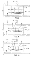
- FIGS. 5-15 are diagrammatic illustrations of apparatus used to form the textured surface panels, showing the successive steps of the fabrication method.
- FIG. 16 is an enlarged illustration of the area indicated by the letter "A" in FIG. 13 .
- FIG. 17 is a simplified flow diagram illustrating the steps of the fabrication method.
- FIG. 18 is an isometric illustration of a press assembly used to fabricate a decorative shell having a textured surface.
- FIG. 19 is a flow diagram of aircraft production and service methodology.
- FIG. 20 is a block diagram of an aircraft.
- the articles may comprise, for example, without limitation, a curved panel 20 used as an interior sidewall in an aircraft or similar vehicle.
- curved panels having decorative surfaces used in aircraft include, for example, without limitation, hatches, bin doors, ceiling panels, etc.
- the panel 20 possesses an overall curvature generally corresponding to that of the aircraft's fuselage, but may also include other simple or compound curves and contours, such as the reliefs 23 that may surround window openings 25.
- the panel 20 broadly comprises an outer composite shell 26 bonded to an inner composite panel 28.
- the shell 26, which faces the interior cabin of the aircraft, may comprise an outer textured film 22 bonded to one or more inner layers 24 of composite materials, such as fiber reinforced polymer materials in fabric or other forms.
- the inner panel 28 may comprise one or more layers 30 of a fiber reinforced polymer, between which there is sandwiched a light-weight, honeycomb core 31 such as, without limitation, NOMEX®. Other types of cores are possible.
- the core 31 has been partially crushed as a result of one process that may be used to fabricate the panel 20, known as crushed core molding, which will be described below.
- FIG. 2a illustrates the panel 20 before crushing of the core 31 during the molding process.
- the inner panel 28 may essentially provide the panel 20 with the required rigidity, while the outer shell 26 functions to cover the surface of the inner panel 28, or for merely decorative purposes.
- the decorative film 22 may employ any desired texture and may be formed of a clear material having printed decorative patterns on the inside face 22a thereof.
- an article such as the panel 20 having a textured surface may be fabricated using a compression molding press 35 which includes a heated compression mold 37.
- the press 35 may be used to carry out a crushed core molding process, in which the mold 37 is used to partially crush the core 31.
- Mold 37 may include a male portion 32 and a female portion 34 respectively mounted on opposing platens 38, 40 of the press 35.
- the male mold portion 32 includes a male feature 42 which may be received within a mold cavity 36 in the female mold portion 34 when the mold 37 is closed.
- a pressurizer 44 whose purpose will be described below, is laterally shiftable to a position overlying the female mold portion 34, above the mold cavity 36.
- the bottom of the mold cavity 36 may be configured to form the outside curvature of the panel 20.
- the first step 60 ( FIG. 17 ) in the fabrication method involves loading a flexible tool in the form of an embossing blanket 46 into the mold cavity 36.
- the embossing blanket 46 may be a planar, flexible sheet-like member having a textured surface 54 on one side thereof.
- the embossing blanket 46 should be sufficiently soft and flexible to conform to the contour of the mold cavity 36, but yet hard enough to emboss a pattern on the film 22 when subjected to the level of pressure applied by the pressurizer 44.
- the embossing blanket 46 should remain flexible after the forming process so that it may be peeled off without damaging the decorative surface left on the film 22, or the textured surface 54 on the blanket 46.
- the decorative pattern formed by the textured surface 54 is imparted to the film 22, thereby embossing the film, as will be discussed below. Due to its flexibility, the embossing blanket 46 conforms to the bottom of the mold cavity 36 and is positioned such that the textured surface 54 faces the male mold portion 32. As a result of the flexibility of the blanket 46 and the vacuum within the mold cavity, the textured surface 54 of the blanket 46 is pressed into the film 22 with sufficient force to emboss the film with the textured pattern of the blanket 46. At this stage, the pressurizer 44 is located disposed in a standby position, outside of the mold 37.
- the decorative charge 45 is loaded into the mold cavity 36 at step 62.
- the decorative charge 45 may comprise a film 22 along with one or more layers 24 of composite material, which may include a pre-preg for example.
- the decorative film 22 may comprise by way of example, without limitation. TEDLAR® available from DuPont Engineering Polymers.
- the decorative charge 45 is placed over the upper surface of the embossing blanket 46 so that the film 22 faces the textured surface 54 of the blanket 46.
- the decorative film 22 may comprise, by way of example, and without limitation, a single or multi-ply plastic laminate, including an optically clear layer of PVF (Polyvinyl Fluoride).
- the film 22 may be bonded to the pre-preg of plies 24 using a layer of film adhesive such as Bostik® embossing film available from Bostik.
- the next step 64 of the fabrication method involves moving the pressurizer 44 in the direction of the arrow 50, laterally into its operative position, overlying the mold cavity 36.
- the edges of the pressurizer 44 are then sealed to the periphery of the mold cavity 36, thereby rendering the mold cavity 36 essentially air tight.
- the pressurizer 44 may comprise any suitable device for imparting pressure of sufficient magnitude against and uniformly across the decorative charge 45.
- the pressurizer 44 may comprise an inflatable bladder or similar pressure chamber.
- step 66 the press 35 is closed, as shown in FIG. 8 and the pressurizer 44 is activated at step 68.
- Activation of the pressurizer 44 may involve supplying air or other fluid under pressure from a source (not shown) to the pressurizer 44 which results in pressurizing the mold cavity 36.
- FIG. 9 shows a bladder 44a having been pressurized and expanding into the mold cavity 36 so as to apply uniform pressure over the upper face of the decorative charge 45. The uniform force applied by the bladder 44a compresses the charge 45 against the bottom of the mold cavity 36, causing the textured surface 54 of the blanket 46 to be embossed into the surface of the decorative film 22.
- the pressure applied by the bladder 44a also results in both the consolidation of the decorative charge 45 and molding of the charge 45 so as to conform to the shape of the mold cavity 36. Because the decorative film 22 and plies 24 form a rigid shell 26, rough areas or mark-off on the panel 28 may not be seen, consequently any rough patches on the inner panel 28 need not be filled in or subsequently smoothed out.
- step 70 the pressurizer 44 is deactivated, resulting in retraction of the bladder 44a, as shown in FIG. 10 .
- a fully formed shell 36 has been produced having essentially the final shape of the panel 20 with a decorative, textured outer surface.
- the press 35 is opened, as shown in FIG. 11 , and the pressurizer 44 moved laterally in the direction of arrow 58 to its standby position (see FIG. 11 ).
- a second charge 56 is introduced into the mold cavity 36 as shown in FIG. 12 , and is placed over the fully formed shell 26 ( FIG. 12 ).
- the second composite charge 56 may comprise a sandwich comprising a core 31 sandwiched between multiple plies 30 of fiber reinforced composite material, for example. Alternatively, the individual plies 30 and core 31 may be laid up over the shell 26, piece-by-piece.
- the next step 76 consists of closing the press 35.
- the second composite charge 56 is consolidated with the shell 26 to form a fully consolidated panel 20.
- the core 31 is partially crushed.
- the panel 20 may remain in the heated mold 37 a requisite period of time to cure the pre-preg materials.
- the next step 78 involves opening the press 35 and removing the finished panel 20, as shown in FIG. 14 .
- the embossing blanket 46 remains adhered to the shell portion 26 of the panel 20.
- the embossing blanket 46 is peeled away from the finished panel 20 as shown in FIG. 14 , and may be reused to emboss additional panels in subsequent molding operations.
- the panel 20 is ready for any necessary secondary processes, such as, without limitation, trimming or attachment of hardware.
- FIG. 18 shows an alternate press arrangement 35a used to form a sample shell 26a.
- the pressurizer 44 is mounted on an upper press platen 38 which may be moved downwardly using guides 84 until the pressurizer 44 is seated around the perimeter of the female mold portion 34.
- the pressurizer 44 shown in FIG. 18 comprises a bladder 82 held within a rigid rectangular frame 86. After the pressurizer 44 has been used to perform the embossing operation, it may be removed from the upper press platen 38 and replaced with a male portion 32 of the mold 37. Subsequently, the core 28a portion of panel 26a is inserted into the mold, the press 35a then closed and the panel 26a formed in the final processing step.
- Embodiments of the disclosure may find use in a variety of potential applications, particularly in the transportation industry, including for example, aerospace and automotive applications.
- embodiments of the disclosure may be used in the context of an aircraft manufacturing and service method 88 as shown in Figure 19 and an aircraft 90 as shown in Figure 20 .
- Aircraft applications of the disclosed embodiments may include, for example, without limitation, composite stiffened members such as fuselage skins, wing skins, control surfaces, hatches, floor panels, door panels, access panels and empennages, to name a few.
- exemplary method 88 may include specification and design 92 of the aircraft 90 and material procurement 94.
- component and subassembly manufacturing 96 and system integration 98 of the aircraft 90 takes place. Thereafter, the aircraft 98 may go through certification and delivery 100 in order to be placed in service 102. While in service by a customer, the aircraft 90 is scheduled for routine maintenance and service 104 (which may also include modification, reconfiguration, refurbishment, and so on).
- Each of the processes of method 88 may be performed or carried out by a system integrator, a third party, and/or an operator (e.g., a customer).
- a system integrator may include without limitation any number of aircraft manufacturers and major-system subcontractors
- a third party may include without limitation any number of venders, subcontractors, and suppliers
- an operator may be an airline, leasing company, military entity, service organization, and so on.
- the aircraft 98 produced by exemplary method 88 may include an airframe 110 with a plurality of systems 106 and an interior 108.
- high-level systems 106 include one or more of a propulsion system 112, an electrical system 114, a hydraulic system 116, and an environmental system 118. Any number of other systems may be included.
- an aerospace example is shown, the principles of the disclosure may be applied to other industries, such as the automotive industry.
- Apparatus and methods embodied herein may be employed during any one or more of the stages of the production and service method 88.
- components or subassemblies corresponding to production process 96 may be fabricated or manufactured in a manner similar to components or subassemblies produced while the aircraft 98 is in service.
- one or more apparatus embodiments, method embodiments, or a combination thereof may be utilized during the production stages 96 and 98, for example, by substantially expediting assembly of or reducing the cost of an aircraft 98.
- apparatus embodiments, method embodiments, or a combination thereof may be utilized while the aircraft 98 is in service, for example and without limitation, to maintenance and service 104.
Landscapes
- Engineering & Computer Science (AREA)
- Mechanical Engineering (AREA)
- Chemical & Material Sciences (AREA)
- Composite Materials (AREA)
- Casting Or Compression Moulding Of Plastics Or The Like (AREA)
- Laminated Bodies (AREA)
Claims (11)
- Verfahren (88) zum Herstellen eines gewölbten Verbundwerkstoffpaneels (20) mit einer dekorativen strukturierten Oberfläche (54), das folgende Schritte aufweist:(A) Verbringen eines flexiblen Werkzeugs mit einer strukturierten Oberfläche (54) in eine Form (37);(B) Verbringen einer ersten Verbundwerkstoffcharge (45) einschließlich einer dekorativen Folie (22) in die Form (37) über das Werkzeug;(C) Prägen der dekorativen Folie (22) durch Eindrücken der strukturierten Oberfläche (54) des Werkzeugs in die dekorative Folie (22) durch einen Druckerhöher (44), während die erste Verbundwerkstoffcharge (45) sich in der Form (37) befindet;(D) Einbringen einer zweiten Verbundwerkstoffcharge (56) in die Form (37) über die erste Verbundwerkstoffcharge (45); und(E) Vereinigen der ersten und zweiten Chargen (45, 46) während des Kompaktierens innerhalb der Form (37).
- Verfahren nach Anspruch 1, wobei Schritt (A) durchgeführt wird, indem eine flexible Prägedecke (46) auf die erste Verbundwerkstoffcharge (45) verbracht wird, während die Form offen ist.
- Verfahren nach Anspruch 1, wobei Schritt (C) Folgendes einschließt:Platzieren eines Druckerhöhers (44) über dem Werkzeug und der ersten Verbundwerkstoffcharge (45), undAnwenden einer Kraft auf eine Oberfläche des Werkzeugs unter Verwendung des Druckerhöhers (44).
- Verfahren nach Anspruch 3, wobei Schritt (C) ferner das Abdichten des Druckerhöhers (44) gegenüber des Umfanges eines Teils der Form (37) einschließt.
- Verfahren nach Anspruch 1, das ferner den folgenden Schritt aufweist:(F) Eindrücken eines Kerns (31) in der zweiten Kompositcharge (56) während des Kompaktierens der ersten und zweiten Kompositchargen (45, 56) innerhalb der Form (37).
- Verfahren nach Anspruch 1, wobei der Schritt (D) das Aufeinanderlegen mehrerer Lagen (24) von Prepreggewebe in der Form (37) aufweist.
- Verfahren nach Anspruch 1, das ferner die folgenden Schritte aufweist(F) Entfernen der Kombination aus dem Paneel (20) und dem Werkzeug aus der Form (37); und(G) Trennen des Werkzeugs von dem Paneel (20).
- Verfahren nach Anspruch 1, das ferner den folgenden Schritt aufweist:(F) Aushärten der vereinigten Chargen während des Kompaktierens innerhalb der Form (37).
- Vorrichtung zum Herstellen eines Gegenstands mit einer profilierten strukturierten Oberfläche (54), die Folgendes aufweist:eine Form (37) mit einem profilierten Formnest (36) zur Aufnahme einer Materialcharge (45);ein flexibles Werkzeug mit einer strukturierten Oberfläche auf einer der Seiten, wobei das flexible Werkzeug entfernbar in zumindest einem Teil des profilierten Formnestes (36) eingebaut ist und der Form zumindest eines Teils des profilierten Formnestes (36) entspricht; undeinen Druckerhöher (44), der über dem Formnest (36) angeordnet werden kann, um die Materialcharge (45) gegen die Kombination des flexiblen Werkzeugs und des Formnestes (36) zu drücken, wobei der Druckerhöher (44) eine aufblasbare Blase (44a) aufweist, wobei die aufblasbare Blase (44a) entfernbar an der Form (37) angebracht ist und um das Formnest (36) gegenüber der Form (37) abgedichtet ist, wobei die Form (37) voneinander trennbare männliche und weibliche Teile (32, 34) aufweist und wobei die aufblasbare Blase (44a) zwischen einer Standbyposition außerhalb der Form (37) und einer betreibbaren Position, die zwischen männlichen und weiblichen Teilen der Form (32, 34) angeordnet ist, verschiebbar ist
- Vorrichtung nach Anspruch 9, wobei
das erste Teil der Form das profilierte Formnest (36) aufweist und
wobei das zweite Teil der Form (32) die männlichen Charakteristika zum Vereinigen der Materialchargen aufweist. - Vorrichtung nach Anspruch 9, wobei das flexible Werkzeug eine Prägedecke (46) aufweist.
Applications Claiming Priority (1)
| Application Number | Priority Date | Filing Date | Title |
|---|---|---|---|
| US11/848,545 US7758786B2 (en) | 2007-08-31 | 2007-08-31 | Method and apparatus for fabricating articles having textured surfaces |
Publications (3)
| Publication Number | Publication Date |
|---|---|
| EP2030764A2 EP2030764A2 (de) | 2009-03-04 |
| EP2030764A3 EP2030764A3 (de) | 2010-09-22 |
| EP2030764B1 true EP2030764B1 (de) | 2013-03-20 |
Family
ID=40085499
Family Applications (1)
| Application Number | Title | Priority Date | Filing Date |
|---|---|---|---|
| EP08163308A Active EP2030764B1 (de) | 2007-08-31 | 2008-08-29 | Verfahren und Vorrichtung zum Herstellen von Gegenständen mit strukturierten Oberflächen |
Country Status (2)
| Country | Link |
|---|---|
| US (1) | US7758786B2 (de) |
| EP (1) | EP2030764B1 (de) |
Families Citing this family (26)
| Publication number | Priority date | Publication date | Assignee | Title |
|---|---|---|---|---|
| US10449736B2 (en) | 2006-02-02 | 2019-10-22 | The Boeing Company | Apparatus for fabricating thermoplastic composite parts |
| DE102011000437A1 (de) * | 2011-02-01 | 2012-08-02 | Dr. Ing. H.C. F. Porsche Aktiengesellschaft | Herstellverfahren für einen flexiblen Verdeckbezug für ein Cabriolet |
| WO2012112470A1 (en) * | 2011-02-14 | 2012-08-23 | Nypro, Inc. | Method of fabricating a textured surface on a molded part |
| US10899045B2 (en) * | 2013-03-12 | 2021-01-26 | U.S.A. As Represented By The Administrator Of The National Aeronautics And Space Administration | High pressure soft lithography for micro-topographical patterning of molded polymers and composites |
| EP2832532A1 (de) | 2013-07-31 | 2015-02-04 | Airbus Operations GmbH | Platte und Herstellungsverfahren dafür |
| US20160229092A1 (en) * | 2013-10-31 | 2016-08-11 | Hewlett-Packard Development Company, L.P. | Textured film on substrate |
| WO2015122882A1 (en) * | 2014-02-12 | 2015-08-20 | Hewlett-Packard Development Company, L.P. | Forming a casing of an electronics device |
| US10751982B2 (en) | 2016-05-12 | 2020-08-25 | The Boeing Company | Methods and apparatus to remove gas and vapor from a panel for a decorative layer |
| US10173394B2 (en) * | 2016-05-12 | 2019-01-08 | The Boeing Company | Methods and apparatus to vent gas and vapor from a panel via venting channels for a decorative layer |
| US10661530B2 (en) | 2016-05-12 | 2020-05-26 | The Boeing Company | Methods and apparatus to couple a decorative layer to a panel via a high-bond adhesive layer |
| US10525685B2 (en) | 2016-05-12 | 2020-01-07 | The Boeing Company | Methods and apparatus to couple a decorative composite having a reinforcing layer to a panel |
| US10647099B2 (en) | 2016-05-12 | 2020-05-12 | The Boeing Company | Methods and apparatus to form venting channels on a panel for a decorative layer |
| US11130318B2 (en) | 2016-05-12 | 2021-09-28 | The Boeing Company | Panels having barrier layers and related methods |
| US10780614B2 (en) | 2016-05-24 | 2020-09-22 | General Electric Company | System and method for forming stacked materials |
| US10611097B2 (en) | 2016-05-24 | 2020-04-07 | General Electric Company | Methods and systems including pressurized housings for forming materials |
| US10207434B2 (en) | 2016-08-04 | 2019-02-19 | The Boeing Company | In-mold apparatus and method for decorative application |
| US10828822B2 (en) | 2016-08-04 | 2020-11-10 | The Boeing Company | Method for fabricating thermoplastic sandwich structural panel using thermoforming and compression molding |
| RU2685218C1 (ru) * | 2017-12-18 | 2019-04-16 | Общество с ограниченной ответственностью "Тулпар Интерьер Групп" | Способ изготовления криволинейной трехслойной композитной панели |
| US11717991B2 (en) * | 2018-03-20 | 2023-08-08 | Sharklet Technologies, Inc. | Molds for manufacturing textured articles, methods of manufacturing thereof and articles manufactured therefrom |
| US12420456B2 (en) | 2018-03-20 | 2025-09-23 | Sharklet Technologies, Inc. | Molds for manufacturing textured articles, methods of manufacturing thereof and articles manufactured therefrom |
| US12083574B2 (en) * | 2018-08-08 | 2024-09-10 | Northwestern University | Serrated surfaces for anti-icing applications |
| US11648738B2 (en) | 2018-10-15 | 2023-05-16 | General Electric Company | Systems and methods of automated film removal |
| US11446884B2 (en) * | 2018-10-29 | 2022-09-20 | Airbus Operations Gmbh | Process for producing a component which is two-dimensional in regions from a fibre composite material |
| US20220126192A1 (en) * | 2019-02-01 | 2022-04-28 | Pda Ecolab, Sas | Sliding board with corrugated mediums |
| US11485096B2 (en) * | 2019-05-17 | 2022-11-01 | The Boeing Company | Method and system for manufacturing composite structures using a magnesium bladder |
| US11691356B2 (en) | 2021-02-08 | 2023-07-04 | General Electric Company | System and method for forming stacked materials |
Family Cites Families (12)
| Publication number | Priority date | Publication date | Assignee | Title |
|---|---|---|---|---|
| US2796634A (en) * | 1953-12-21 | 1957-06-25 | Ibm | Reverse forming process for making shaped articles from plastic sheet material |
| AT377228B (de) * | 1980-07-24 | 1985-02-25 | Lignotock Verfahrenstech | Verfahren und vorrichtung zum herstellen von formteilen aus ebenen wirrfaservliesmatten, vorzugsweise aus mit bindemittel versehenen zellulose-oder lignozellulosefasern |
| US4608220A (en) * | 1984-12-20 | 1986-08-26 | The Boeing Company | Method of forming composite material articles |
| JPH02126434A (ja) * | 1988-11-05 | 1990-05-15 | Mitsubishi Electric Corp | 光デイスク基板成形方法 |
| FR2670427B1 (fr) * | 1990-12-18 | 1994-07-08 | Francois Savigny | Procede de moulage sous vide d'un panneau en materiau plastique et panneau obtenu selon le procede. |
| GB2259883A (en) * | 1991-09-28 | 1993-03-31 | Rover Group | Moulding against a shape or surface imparting film liner |
| FR2693146B1 (fr) * | 1992-07-02 | 1994-08-19 | Snecma | Installation pour la fabrication par drapage de structures multicouches en matériaux composites. |
| US6319346B1 (en) * | 1997-04-23 | 2001-11-20 | Radius Engineering, Inc. | Method for manufacture of composite aircraft control surfaces |
| US6699419B1 (en) * | 2000-06-05 | 2004-03-02 | General Motors Corporation | Method of forming a composite article with a textured surface and mold therefor |
| ES2211262B1 (es) * | 2001-12-12 | 2005-07-16 | Totalstone, S.A. | Procedimiento para la obtencion de reproducciones murales y arquitectonicas, y producto resultante. |
| US7452493B2 (en) * | 2005-04-15 | 2008-11-18 | The Boeing Company | Protective cover and tool splash for vehicle components |
| ES2281269B1 (es) * | 2005-11-30 | 2008-09-01 | Eramat Composites Plasticos, S.L. | Procedimiento y equipo de obtencion de un producto laminar, y el producto obtenido. |
-
2007
- 2007-08-31 US US11/848,545 patent/US7758786B2/en active Active
-
2008
- 2008-08-29 EP EP08163308A patent/EP2030764B1/de active Active
Also Published As
| Publication number | Publication date |
|---|---|
| EP2030764A3 (de) | 2010-09-22 |
| US20090057947A1 (en) | 2009-03-05 |
| EP2030764A2 (de) | 2009-03-04 |
| US7758786B2 (en) | 2010-07-20 |
Similar Documents
| Publication | Publication Date | Title |
|---|---|---|
| US7758786B2 (en) | Method and apparatus for fabricating articles having textured surfaces | |
| US8465613B2 (en) | Method and apparatus for fabricating variable gauge, contoured composite stiffeners | |
| EP2906412B1 (de) | Verfahren und vorrichtung zur herstellung von faserverbundteilen | |
| US9254619B2 (en) | Method and apparatus for fabricating variable gauge, contoured composite stiffeners | |
| EP2402134B1 (de) | Herstellungsverfahren eines faltbaren Formkerns mit verstärkter Fluorelastomerblase | |
| US8613301B2 (en) | Compaction of prepreg plies on composite laminate structures | |
| EP2569142B1 (de) | Herstellungsverfahren für eine verbund-sandwichstruktur | |
| EP0904929A1 (de) | Verfahren zum Formen eines inneren Druckstücks während des Formen eines Produktes | |
| AU2018267651B2 (en) | Radius filler kits and composite forming method | |
| US10828822B2 (en) | Method for fabricating thermoplastic sandwich structural panel using thermoforming and compression molding | |
| US9994008B2 (en) | Method and system for compacting composite part layup utilizing a single release film layer | |
| US11305498B2 (en) | System and method for fabricating a composite ply layup | |
| US7662334B2 (en) | Vacuum heat-set of net shape latex vacuum bags | |
| US20210107239A1 (en) | Flexible Caul and Method of Making the Same | |
| WO2014200675A1 (en) | Method and apparatus for fabricating composite stringers | |
| US9221236B1 (en) | Systems and methods for assembling stiffened composite structures | |
| US11738526B2 (en) | Method for using composite tooling to manufacture composite parts | |
| CN115723351A (zh) | 用于成型高轮廓复合结构的成型设备及相关方法 | |
| EP3738754B1 (de) | Verfahren zum formen einer verbundstruktur mit einer superplastischen blase | |
| EP3629001A1 (de) | Testsystem und verfahren zur erzeugung von gesteuerter und wiederholbarer faserverschiebung ausserhalb der ebene in verbundlaminaten | |
| EP3800038B1 (de) | Formsystem und verfahren zur herstellung von strukturen | |
| JP2019135097A (ja) | 圧潰エッジ領域を有する複合サンドイッチパネル | |
| RU2832222C1 (ru) | Способ изготовления композитного многослойного изделия | |
| CN110722815A (zh) | 一种轻质高强碳纤维便携箱的模块化成型工艺 | |
| US10913221B2 (en) | Shaping a radius filler against a mandrel |
Legal Events
| Date | Code | Title | Description |
|---|---|---|---|
| PUAI | Public reference made under article 153(3) epc to a published international application that has entered the european phase |
Free format text: ORIGINAL CODE: 0009012 |
|
| AK | Designated contracting states |
Kind code of ref document: A2 Designated state(s): AT BE BG CH CY CZ DE DK EE ES FI FR GB GR HR HU IE IS IT LI LT LU LV MC MT NL NO PL PT RO SE SI SK TR |
|
| AX | Request for extension of the european patent |
Extension state: AL BA MK RS |
|
| RIC1 | Information provided on ipc code assigned before grant |
Ipc: B29C 43/36 20060101ALI20100709BHEP Ipc: B29C 70/78 20060101ALI20100709BHEP Ipc: B29C 33/42 20060101ALI20100709BHEP Ipc: B29C 43/18 20060101ALI20100709BHEP Ipc: B29C 70/54 20060101ALI20100709BHEP Ipc: B29C 70/44 20060101AFI20100709BHEP Ipc: B29C 43/02 20060101ALN20100709BHEP Ipc: B29C 33/50 20060101ALI20100709BHEP |
|
| PUAL | Search report despatched |
Free format text: ORIGINAL CODE: 0009013 |
|
| AK | Designated contracting states |
Kind code of ref document: A3 Designated state(s): AT BE BG CH CY CZ DE DK EE ES FI FR GB GR HR HU IE IS IT LI LT LU LV MC MT NL NO PL PT RO SE SI SK TR |
|
| AX | Request for extension of the european patent |
Extension state: AL BA MK RS |
|
| 17P | Request for examination filed |
Effective date: 20110223 |
|
| AKX | Designation fees paid |
Designated state(s): AT BE BG CH CY CZ DE DK EE ES FI FR GB GR HR HU IE IS IT LI LT LU LV MC MT NL NO PL PT RO SE SI SK TR |
|
| REG | Reference to a national code |
Ref country code: DE Ref legal event code: R079 Ref document number: 602008022992 Country of ref document: DE Free format text: PREVIOUS MAIN CLASS: B29C0070460000 Ipc: B29C0070440000 |
|
| RIC1 | Information provided on ipc code assigned before grant |
Ipc: B29C 33/50 20060101ALI20120702BHEP Ipc: B29C 43/18 20060101ALI20120702BHEP Ipc: B29C 43/02 20060101ALN20120702BHEP Ipc: B29C 70/78 20060101ALI20120702BHEP Ipc: B29C 43/36 20060101ALI20120702BHEP Ipc: B29C 70/54 20060101ALI20120702BHEP Ipc: B29C 70/44 20060101AFI20120702BHEP Ipc: B29C 33/42 20060101ALI20120702BHEP |
|
| RIC1 | Information provided on ipc code assigned before grant |
Ipc: B29C 43/36 20060101ALI20120711BHEP Ipc: B29C 33/50 20060101ALI20120711BHEP Ipc: B29C 43/18 20060101ALI20120711BHEP Ipc: B29C 70/44 20060101AFI20120711BHEP Ipc: B29C 70/78 20060101ALI20120711BHEP Ipc: B29C 43/02 20060101ALN20120711BHEP Ipc: B29C 33/42 20060101ALI20120711BHEP Ipc: B29C 70/54 20060101ALI20120711BHEP |
|
| GRAP | Despatch of communication of intention to grant a patent |
Free format text: ORIGINAL CODE: EPIDOSNIGR1 |
|
| GRAS | Grant fee paid |
Free format text: ORIGINAL CODE: EPIDOSNIGR3 |
|
| GRAA | (expected) grant |
Free format text: ORIGINAL CODE: 0009210 |
|
| AK | Designated contracting states |
Kind code of ref document: B1 Designated state(s): AT BE BG CH CY CZ DE DK EE ES FI FR GB GR HR HU IE IS IT LI LT LU LV MC MT NL NO PL PT RO SE SI SK TR |
|
| REG | Reference to a national code |
Ref country code: GB Ref legal event code: FG4D |
|
| REG | Reference to a national code |
Ref country code: CH Ref legal event code: EP |
|
| REG | Reference to a national code |
Ref country code: IE Ref legal event code: FG4D |
|
| REG | Reference to a national code |
Ref country code: AT Ref legal event code: REF Ref document number: 601794 Country of ref document: AT Kind code of ref document: T Effective date: 20130415 |
|
| REG | Reference to a national code |
Ref country code: DE Ref legal event code: R096 Ref document number: 602008022992 Country of ref document: DE Effective date: 20130516 |
|
| PG25 | Lapsed in a contracting state [announced via postgrant information from national office to epo] |
Ref country code: SE Free format text: LAPSE BECAUSE OF FAILURE TO SUBMIT A TRANSLATION OF THE DESCRIPTION OR TO PAY THE FEE WITHIN THE PRESCRIBED TIME-LIMIT Effective date: 20130320 Ref country code: BG Free format text: LAPSE BECAUSE OF FAILURE TO SUBMIT A TRANSLATION OF THE DESCRIPTION OR TO PAY THE FEE WITHIN THE PRESCRIBED TIME-LIMIT Effective date: 20130620 Ref country code: NO Free format text: LAPSE BECAUSE OF FAILURE TO SUBMIT A TRANSLATION OF THE DESCRIPTION OR TO PAY THE FEE WITHIN THE PRESCRIBED TIME-LIMIT Effective date: 20130620 Ref country code: ES Free format text: LAPSE BECAUSE OF FAILURE TO SUBMIT A TRANSLATION OF THE DESCRIPTION OR TO PAY THE FEE WITHIN THE PRESCRIBED TIME-LIMIT Effective date: 20130701 Ref country code: LT Free format text: LAPSE BECAUSE OF FAILURE TO SUBMIT A TRANSLATION OF THE DESCRIPTION OR TO PAY THE FEE WITHIN THE PRESCRIBED TIME-LIMIT Effective date: 20130320 |
|
| REG | Reference to a national code |
Ref country code: AT Ref legal event code: MK05 Ref document number: 601794 Country of ref document: AT Kind code of ref document: T Effective date: 20130320 |
|
| REG | Reference to a national code |
Ref country code: LT Ref legal event code: MG4D |
|
| PG25 | Lapsed in a contracting state [announced via postgrant information from national office to epo] |
Ref country code: FI Free format text: LAPSE BECAUSE OF FAILURE TO SUBMIT A TRANSLATION OF THE DESCRIPTION OR TO PAY THE FEE WITHIN THE PRESCRIBED TIME-LIMIT Effective date: 20130320 Ref country code: SI Free format text: LAPSE BECAUSE OF FAILURE TO SUBMIT A TRANSLATION OF THE DESCRIPTION OR TO PAY THE FEE WITHIN THE PRESCRIBED TIME-LIMIT Effective date: 20130320 Ref country code: LV Free format text: LAPSE BECAUSE OF FAILURE TO SUBMIT A TRANSLATION OF THE DESCRIPTION OR TO PAY THE FEE WITHIN THE PRESCRIBED TIME-LIMIT Effective date: 20130320 Ref country code: GR Free format text: LAPSE BECAUSE OF FAILURE TO SUBMIT A TRANSLATION OF THE DESCRIPTION OR TO PAY THE FEE WITHIN THE PRESCRIBED TIME-LIMIT Effective date: 20130621 |
|
| REG | Reference to a national code |
Ref country code: NL Ref legal event code: VDEP Effective date: 20130320 |
|
| PG25 | Lapsed in a contracting state [announced via postgrant information from national office to epo] |
Ref country code: BE Free format text: LAPSE BECAUSE OF FAILURE TO SUBMIT A TRANSLATION OF THE DESCRIPTION OR TO PAY THE FEE WITHIN THE PRESCRIBED TIME-LIMIT Effective date: 20130320 Ref country code: HR Free format text: LAPSE BECAUSE OF FAILURE TO SUBMIT A TRANSLATION OF THE DESCRIPTION OR TO PAY THE FEE WITHIN THE PRESCRIBED TIME-LIMIT Effective date: 20130320 |
|
| PG25 | Lapsed in a contracting state [announced via postgrant information from national office to epo] |
Ref country code: SK Free format text: LAPSE BECAUSE OF FAILURE TO SUBMIT A TRANSLATION OF THE DESCRIPTION OR TO PAY THE FEE WITHIN THE PRESCRIBED TIME-LIMIT Effective date: 20130320 Ref country code: EE Free format text: LAPSE BECAUSE OF FAILURE TO SUBMIT A TRANSLATION OF THE DESCRIPTION OR TO PAY THE FEE WITHIN THE PRESCRIBED TIME-LIMIT Effective date: 20130320 Ref country code: CZ Free format text: LAPSE BECAUSE OF FAILURE TO SUBMIT A TRANSLATION OF THE DESCRIPTION OR TO PAY THE FEE WITHIN THE PRESCRIBED TIME-LIMIT Effective date: 20130320 Ref country code: RO Free format text: LAPSE BECAUSE OF FAILURE TO SUBMIT A TRANSLATION OF THE DESCRIPTION OR TO PAY THE FEE WITHIN THE PRESCRIBED TIME-LIMIT Effective date: 20130320 Ref country code: AT Free format text: LAPSE BECAUSE OF FAILURE TO SUBMIT A TRANSLATION OF THE DESCRIPTION OR TO PAY THE FEE WITHIN THE PRESCRIBED TIME-LIMIT Effective date: 20130320 Ref country code: NL Free format text: LAPSE BECAUSE OF FAILURE TO SUBMIT A TRANSLATION OF THE DESCRIPTION OR TO PAY THE FEE WITHIN THE PRESCRIBED TIME-LIMIT Effective date: 20130320 Ref country code: IS Free format text: LAPSE BECAUSE OF FAILURE TO SUBMIT A TRANSLATION OF THE DESCRIPTION OR TO PAY THE FEE WITHIN THE PRESCRIBED TIME-LIMIT Effective date: 20130720 Ref country code: PT Free format text: LAPSE BECAUSE OF FAILURE TO SUBMIT A TRANSLATION OF THE DESCRIPTION OR TO PAY THE FEE WITHIN THE PRESCRIBED TIME-LIMIT Effective date: 20130722 |
|
| PG25 | Lapsed in a contracting state [announced via postgrant information from national office to epo] |
Ref country code: PL Free format text: LAPSE BECAUSE OF FAILURE TO SUBMIT A TRANSLATION OF THE DESCRIPTION OR TO PAY THE FEE WITHIN THE PRESCRIBED TIME-LIMIT Effective date: 20130320 Ref country code: CY Free format text: LAPSE BECAUSE OF FAILURE TO SUBMIT A TRANSLATION OF THE DESCRIPTION OR TO PAY THE FEE WITHIN THE PRESCRIBED TIME-LIMIT Effective date: 20130320 |
|
| PLBE | No opposition filed within time limit |
Free format text: ORIGINAL CODE: 0009261 |
|
| STAA | Information on the status of an ep patent application or granted ep patent |
Free format text: STATUS: NO OPPOSITION FILED WITHIN TIME LIMIT |
|
| PG25 | Lapsed in a contracting state [announced via postgrant information from national office to epo] |
Ref country code: DK Free format text: LAPSE BECAUSE OF FAILURE TO SUBMIT A TRANSLATION OF THE DESCRIPTION OR TO PAY THE FEE WITHIN THE PRESCRIBED TIME-LIMIT Effective date: 20130320 |
|
| 26N | No opposition filed |
Effective date: 20140102 |
|
| PG25 | Lapsed in a contracting state [announced via postgrant information from national office to epo] |
Ref country code: IT Free format text: LAPSE BECAUSE OF FAILURE TO SUBMIT A TRANSLATION OF THE DESCRIPTION OR TO PAY THE FEE WITHIN THE PRESCRIBED TIME-LIMIT Effective date: 20130320 |
|
| REG | Reference to a national code |
Ref country code: CH Ref legal event code: PL |
|
| REG | Reference to a national code |
Ref country code: DE Ref legal event code: R097 Ref document number: 602008022992 Country of ref document: DE Effective date: 20140102 |
|
| PG25 | Lapsed in a contracting state [announced via postgrant information from national office to epo] |
Ref country code: MC Free format text: LAPSE BECAUSE OF FAILURE TO SUBMIT A TRANSLATION OF THE DESCRIPTION OR TO PAY THE FEE WITHIN THE PRESCRIBED TIME-LIMIT Effective date: 20130320 Ref country code: CH Free format text: LAPSE BECAUSE OF NON-PAYMENT OF DUE FEES Effective date: 20130831 Ref country code: LI Free format text: LAPSE BECAUSE OF NON-PAYMENT OF DUE FEES Effective date: 20130831 |
|
| REG | Reference to a national code |
Ref country code: IE Ref legal event code: MM4A |
|
| PG25 | Lapsed in a contracting state [announced via postgrant information from national office to epo] |
Ref country code: IE Free format text: LAPSE BECAUSE OF NON-PAYMENT OF DUE FEES Effective date: 20130829 |
|
| PG25 | Lapsed in a contracting state [announced via postgrant information from national office to epo] |
Ref country code: MT Free format text: LAPSE BECAUSE OF FAILURE TO SUBMIT A TRANSLATION OF THE DESCRIPTION OR TO PAY THE FEE WITHIN THE PRESCRIBED TIME-LIMIT Effective date: 20130320 Ref country code: TR Free format text: LAPSE BECAUSE OF FAILURE TO SUBMIT A TRANSLATION OF THE DESCRIPTION OR TO PAY THE FEE WITHIN THE PRESCRIBED TIME-LIMIT Effective date: 20130320 |
|
| PG25 | Lapsed in a contracting state [announced via postgrant information from national office to epo] |
Ref country code: LU Free format text: LAPSE BECAUSE OF NON-PAYMENT OF DUE FEES Effective date: 20130829 Ref country code: HU Free format text: LAPSE BECAUSE OF FAILURE TO SUBMIT A TRANSLATION OF THE DESCRIPTION OR TO PAY THE FEE WITHIN THE PRESCRIBED TIME-LIMIT; INVALID AB INITIO Effective date: 20080829 |
|
| REG | Reference to a national code |
Ref country code: FR Ref legal event code: PLFP Year of fee payment: 9 |
|
| REG | Reference to a national code |
Ref country code: FR Ref legal event code: PLFP Year of fee payment: 10 |
|
| REG | Reference to a national code |
Ref country code: FR Ref legal event code: PLFP Year of fee payment: 11 |
|
| P01 | Opt-out of the competence of the unified patent court (upc) registered |
Effective date: 20230516 |
|
| PGFP | Annual fee paid to national office [announced via postgrant information from national office to epo] |
Ref country code: DE Payment date: 20250827 Year of fee payment: 18 |
|
| PGFP | Annual fee paid to national office [announced via postgrant information from national office to epo] |
Ref country code: GB Payment date: 20250827 Year of fee payment: 18 |
|
| PGFP | Annual fee paid to national office [announced via postgrant information from national office to epo] |
Ref country code: FR Payment date: 20250825 Year of fee payment: 18 |