EP2030818B1 - Kraftfahrzeugklimaanlagemischluftstromverteilvorrichtung - Google Patents
Kraftfahrzeugklimaanlagemischluftstromverteilvorrichtung Download PDFInfo
- Publication number
- EP2030818B1 EP2030818B1 EP08162962A EP08162962A EP2030818B1 EP 2030818 B1 EP2030818 B1 EP 2030818B1 EP 08162962 A EP08162962 A EP 08162962A EP 08162962 A EP08162962 A EP 08162962A EP 2030818 B1 EP2030818 B1 EP 2030818B1
- Authority
- EP
- European Patent Office
- Prior art keywords
- flap
- distribution
- mixing
- mixed airflow
- generating
- Prior art date
- Legal status (The legal status is an assumption and is not a legal conclusion. Google has not performed a legal analysis and makes no representation as to the accuracy of the status listed.)
- Active
Links
Images


Classifications
-
- B—PERFORMING OPERATIONS; TRANSPORTING
- B60—VEHICLES IN GENERAL
- B60H—ARRANGEMENTS OF HEATING, COOLING, VENTILATING OR OTHER AIR-TREATING DEVICES SPECIALLY ADAPTED FOR PASSENGER OR GOODS SPACES OF VEHICLES
- B60H1/00—Heating, cooling or ventilating devices
- B60H1/00642—Control systems or circuits; Control members or indication devices for heating, cooling or ventilating devices
- B60H1/00664—Construction or arrangement of damper doors
- B60H1/00671—Damper doors moved by rotation; Grilles
- B60H1/00678—Damper doors moved by rotation; Grilles the axis of rotation being in the door plane, e.g. butterfly doors
-
- B—PERFORMING OPERATIONS; TRANSPORTING
- B60—VEHICLES IN GENERAL
- B60H—ARRANGEMENTS OF HEATING, COOLING, VENTILATING OR OTHER AIR-TREATING DEVICES SPECIALLY ADAPTED FOR PASSENGER OR GOODS SPACES OF VEHICLES
- B60H1/00—Heating, cooling or ventilating devices
- B60H1/00642—Control systems or circuits; Control members or indication devices for heating, cooling or ventilating devices
- B60H1/00664—Construction or arrangement of damper doors
- B60H1/00671—Damper doors moved by rotation; Grilles
- B60H1/00685—Damper doors moved by rotation; Grilles the door being a rotating disc or cylinder or part thereof
-
- B—PERFORMING OPERATIONS; TRANSPORTING
- B60—VEHICLES IN GENERAL
- B60H—ARRANGEMENTS OF HEATING, COOLING, VENTILATING OR OTHER AIR-TREATING DEVICES SPECIALLY ADAPTED FOR PASSENGER OR GOODS SPACES OF VEHICLES
- B60H1/00—Heating, cooling or ventilating devices
- B60H1/00642—Control systems or circuits; Control members or indication devices for heating, cooling or ventilating devices
- B60H1/00814—Control systems or circuits characterised by their output, for controlling particular components of the heating, cooling or ventilating installation
- B60H1/00821—Control systems or circuits characterised by their output, for controlling particular components of the heating, cooling or ventilating installation the components being ventilating, air admitting or air distributing devices
- B60H1/00835—Damper doors, e.g. position control
- B60H1/00842—Damper doors, e.g. position control the system comprising a plurality of damper doors; Air distribution between several outlets
Definitions
- the present invention is in the field of heating, ventilation and / or air conditioning, in particular a motor vehicle. It relates to an integrated distribution flap in such an installation, a device for generating a mixed air flow equipped with such a distribution flap and an installation housing such a device.
- a mixing device comprising a shutter is known from the document DE 101 61 997 which is considered the closest prior art.
- a motor vehicle is commonly equipped with a heating, ventilation and / or air conditioning system which is intended to regulate the temperature of the air contained inside the passenger compartment of the vehicle.
- the installation comprises a housing delimited by a partition through which openings are provided, including at least one air inlet and at least one air outlet.
- the housing houses a blower or motor-fan unit for circulating a flow of air from the air inlet to the air outlet and means for heat treatment of the air flow to heat and / or cool the flow of air prior to distribution inside the passenger compartment through the air outlet.
- the means for heat treatment of the air flow comprise an evaporator which is, in particular, intended to cool the flow of air passing therethrough and a radiator, possibly associated with an additional radiator, notably electrical consisting of a series of electrical resistors. which is intended to heat the flow of air passing through it.
- the evaporator is placed after the air inlet of the housing so that all of the incoming air flow is cooled. A fraction of the cooled air stream is heated by the radiator.
- the housing comprises a device capable of generating a mixed air flow from the cooled air flow and the heated air flow. These measures comprises a mixing chamber of a cold air flow from the cooled air flow and a hot air flow from the heated air flow.
- the mixing chamber is delimited by a casing constituting the housing. This envelope is provided with a cold air intake inlet, an inlet of the hot air flow and at least one outlet of the mixed air flow.
- the mixing chamber constitutes an enclosure inside which a mixing flap is movable between a first position in which it closes the inlet mouth of the cold air flow, and a second position in which it closes the mouth of admission of the hot air flow inside the mixing chamber.
- a mixing flap When the mixing flap is placed in an intermediate position between the first and the second position, it allows the simultaneous passage of a cold air flow and a hot air flow in respective variable proportions to generate a flow of air. mixed air inside the mixing chamber.
- Such mixing flap is for example of the type 'drum' mobile in rotation about an axis.
- the mixing flap comprises a closure wall shaped as a cylinder portion constituting a shutter member of the intake port of the cold air flow and / or the inlet of the flow of air. 'hot air.
- the closure wall is connected to the axis of rotation of the mixing flap via flanges, in particular shaped as a circular disk portion.
- the housing is provided with at least one mixed air outlet equipped with a distribution flap.
- This distribution flap is operable between an open position in which it allows a flow of air through the air outlet and a closed position in which it prohibits such circulation.
- An air distribution channel is in aeraulic communication with the mixed air outlet for conveying the mixed air flow to a specific area of the passenger compartment, such as a front zone and / or a rear zone, a zone right and / or a left zone, a foot zone, or even an area defined by any combination of these criteria.
- the distribution flap is indifferently articulated on the housing or in the distribution channel.
- the distribution flap consists mainly of a wall delimited by a peripheral periphery which is of a conformation similar to that of the mixed air outlet.
- the wall is able to register inside the opening forming the mixed air outlet to close the latter.
- the wall is rotatable about itself around a hinge element that it comprises, so that the distribution flap can be placed in any position between its open position and its closing position.
- such an installation is bulky and the terms of connection of the air distribution channel with the mixed air outlet are complex and cause an increase in the overall size of the installation. More particularly, such a mixed air outlet is frequently placed in an inaccessible zone of the installation so that the distribution channel has a complex conformation, generally source of pressure losses for the mixed air flow conveyed by the distribution channel. Moreover, the space allocated to such an air outlet can be reduced. It follows that this channel is likely to have a smaller section. This is not satisfactory with regard to the operation and performance of the installation. It finally emerges that such a distribution component deserves to be improved in order to enable easy and rapid a Vogellic communication of the distribution channel with the corresponding mixed air outlet.
- a first object of the present invention is to provide a distribution flap which is adapted to equip a heating, ventilation and / or air conditioning of a motor vehicle being disposed in any place of the latter and in particular near a structural element that it comprises.
- a second object of the present invention is to provide a device for generating a mixed air flow equipped with such a distribution flap whose compactness is the largest possible.
- a third object of the present invention is to provide a heating, ventilation and / or air conditioning system for diffusing an effective and lasting air flow of an area of the passenger compartment of the vehicle from a mixed air flow whose pressure losses are reduced to the maximum, this mixed air flow being conveyed by a distribution channel whose conformation is simple, preferably rectilinear.
- a fourth object of the present invention is to provide such an installation which also allows airing with the best thermal performance possible a cabin area requiring a mixed air flow relatively hotter or colder than other flows of air leaving the installation ..
- the present invention provides a device for generating a mixed air flow comprising a mixing chamber housing a mixing flap, and comprising at least one distribution flap rotatable around a hinge element.
- the mixing flap comprises a lateral passage allowing rotation of the distribution flap.
- the shape of the flap is dependent on the disposition of the area of a vent and its location in the heating, ventilation and / or air conditioning system.
- the mixing flap comprises a closure wall, an axis of rotation and at least one flange forming a connection between the closure wall and the axis of rotation of the mixing flap.
- the flange is disposed at a distance D from an extreme edge of the mixing flap providing the lateral passage between the extreme edge and the flange of the mixing flap.
- the mixing flap and the distribution flaps operate in the same area of the heating, ventilation and / or air conditioning system. More particularly, the mixing flap does not include flanges that are arranged at the ends of the mixing flap. Thus, the available space makes it possible to house the distribution flap.
- the hinge element of the distribution flap is preferably orthogonal to the axis of rotation of the mixing flap.
- the hinge element of the distribution flap is arranged according to the architecture of the heating, ventilation and / or air conditioning system.
- the axis of rotation of the mixing flap and the articulation element of the distribution flap can therefore be orthogonal to each other, parallel to each other or else arranged in different directions.
- the articulation element of the distribution flap is articulated on an envelope delimiting the mixing chamber or on a distribution channel of the mixed air flow.
- the distribution channel of the mixed air flow is in aeration relationship with a discharge outlet of the mixed air flow formed through the casing.
- the distribution channel is adapted to be operated to ventilate a specific area of the passenger compartment of the vehicle, such as a front ventilation zone, a front foot zone, a rear foot zone or a zone back.
- the aeraulic link between the distribution channel and the envelope is arranged in an easily accessible zone so that the distribution channel has a simple overall configuration, preferably rectilinear, and in any case free of sudden variations in geometries generating pressure losses for the mixed air flow conveyed by the distribution channel.
- the outlet mouth of the mixed air flow is likely to be disposed near an inlet mouth of a flow of hot air formed through the casing so that the mixed air flow transported through the dispensing channel can ventilate an area of the passenger compartment of the vehicle requiring ventilation that is frequently hotter than other areas, such as a back or front foot zone.
- the outlet mouth of the mixed air flow is likely to be disposed near an inlet mouth of a cold air flow formed through the casing so that the flow of air mixed air conveyed through the distribution channel may ventilate an area of the passenger compartment of the vehicle requiring aeration frequently cooler than other areas.
- the flange is formed of at least two connecting arms between the axis of rotation and the shutter wall of the mixing flap, which, according to an alternative embodiment, define together with the closure wall a recess for a passage of the mixed air flow.
- a particular embodiment of the distribution flap consists in that the flap comprises a wall comprising a clearance adapted to constitute a passage for the axis of rotation of the mixing flap.
- the wall is delimited by a peripheral periphery comprising two points of inflection delimiting the clearance.
- the clearance provided in the proi is delimited by a first curve C1.
- This clearance constitutes a passage for an obstacle placed on the trajectory of the distribution flap when rotating on itself. It finally emerges that such a distribution flap is likely to be installed anywhere in a heating, ventilation and / or air conditioning installation, and in particular closer to a structural element that includes the latter. . It follows that the overall compactness of the installation is significantly improved. Moreover, the presence of such a clearance allows a saving of material for the realization of the dispensing flap and gives it an ease of production, particularly by molding.
- the distribution flap and the mixing flap are able to be arranged close to each other, the release of the distribution flap constituting a passage for the axis of rotation of the mixing flap. .
- the combination of the mixing and dispensing functions as presented in the present invention makes it possible to obtain the most compact installation possible.
- a heating, ventilation and / or air conditioning system according to the invention is mainly recognizable in that it houses such a device for generating a mixed air flow.
- a heating, ventilation and / or air conditioning system 1 is intended to equip a motor vehicle to regulate the temperature of the air contained in the passenger compartment of the vehicle.
- the installation 1 comprises a housing 2 provided with an air inlet 3 and a plurality of air outlets 4.
- the housing 2 houses a blower, not shown in the figures, for circulating a flow of air 5 from the air inlet 3 to the air outlets 4.
- the housing 2 also houses a filter 6 to retain particles carried by the air stream 5. Downstream of the filter 6 in the direction of flow of the air air flow 5, the housing 2 houses an evaporator 7 for cooling the incoming air flow into a cold air flow.
- the cold air flow is distributed in a first fraction of air flow admitted inside a mixing chamber 10, visible on the figures 2 and 3 , and in a second fraction of air flow admitted inside a heating chamber 12.
- This distribution is for example carried out by means of an air distribution member 13, in particular of the butterfly shutter type whose only axis is visible in the figures.
- the heating chamber 12 houses a radiator 14 and an additional radiator 15, in particular thermal resistors, for heating the second fraction of air flow, prior to its evacuation from the heating chamber 12 to the mixing chamber 10.
- the mixed air flow is discharged from the mixing chamber 10 by the air outlets 4.
- the supply of the air outlets 4 may to be done directly or through an air distribution channel 18 to feed a particular area of the passenger compartment of the vehicle.
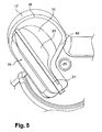
- FIGS. 2 , 3 , 5 and 6 show views schematically representing in perspective a device for generating a mixed air flow participating in the installation and equipped with the dispensing shutter respectively illustrated in the open and closed position.
- figures 5 and 6 are enlarged views of the present invention respectively detailed at figures 2 and 3 .
- the installation 1 is shown schematically in perspective in which the distribution channel 18 has been removed.
- the mixing chamber 10 is advantageously equipped with at least one mixed air outlet 16 which is formed through a casing 17 delimiting the mixing chamber 10 and constituting the casing 2.
- Such a location of the outlet d Mixed air 16 limits the overall size of the installation 1 and gives the installation 1 improved compactness.
- such a location makes it possible to easily place aerated communication air outlet 16 mixed with the air distribution channel 18, visible on the figure 1 , in an area of the facility 1 easily accessible.
- the distribution channel 18 is likely to have a simple conformation, preferably predominantly rectilinear, which tends to reduce the pressure losses experienced by the mixed air flow conveyed by the distribution channel 18 while ensuring an overall compactness optimized.
- the mixed air outlet 16 is equipped with a distribution flap 19 which is rotatable on itself between an open position, represented on the figures 2 and 5 , in which it allows a flow of air through the mixed air outlet 16 to the distribution channel 18 and a closed position, shown in FIGS. figures 3 and 6 in which it prohibits air circulation through the mixed air outlet 16.
- the distribution flap 19 consists of a wall 20. It is rotatable about a hinge member 21.
- the hinge element 21 of the distribution flap 19, for example an axis, is articulated on the envelope 17 delimiting the mixing chamber 10.
- the distribution flap 19 is articulated in the distribution channel 18 which is in aeraulic relationship with a discharge outlet 40 of the mixed air flow provided at through the envelope 17.
- the installation 1 is schematically represented in perspective the installation as detailed on the figures 2 and 3 in which the distribution flap 19 has been removed.
- the mixing chamber 10 houses a mixing flap 22 movable between two extreme positions. In a first extreme position, the mixing flap 22 closes an inlet mouth of the cold air flow formed through the casing 17. In a second extreme position, the mixing flap 22 closes an inlet mouth of the flow of hot air formed through the casing 17.
- the inlet of the cold air flow is an air passage for the first fraction of air flow admitted directly inside a mixing chamber While the inlet mouth of the hot air flow constitutes an air passage for the second fraction of air flow admitted inside a heating chamber 12.
- the mixing flap 22 is articulated on the housing 2 via an axis of rotation 25.
- the mixing flap 22 comprises at least one flange 30 constituting a connection between the axis of rotation 25 and a closure wall 28 of the mixing flap 22.
- the closure wall 28 is intended to at least partially close one of the inlet mouths of the cold air flow and / or the hot air flow, so as to generate a flow mixed air whose temperature may range between that of the first fraction of cold air flow and that of the second fraction of air flow admitted inside a heating chamber 12.
- the mixing flap 22 comprises two lateral flanges 30 between which a medial flange 31 is interposed.
- the lateral flanges 30 are arranged at a distance from one another. distance D of a respective extreme edge 32 of the mixing flap 22.
- This offset of the side flanges 30 towards the inside of the mixing flap 22 allows to provide a lateral passage 33 in which each of the distribution flaps 19 is able to be movable in rotation around the hinge member 21.
- the distribution flaps 19 are moved in the lateral passage 33 of the mixing flap 22.
- the distance D between the flange 30 and the end edge 32 of the mixing flap 22 is between 10% and 30% of a length L of the mixing flap.
- the figure 8 differs from the example described in figure 7 by the position of the mixing flap 22.
- the mixing flap 22 has been rotated clockwise about the axis 25 relative to the position which was its own. figure 7 .
- the position of the distribution flaps 19 in figures 7 and 8 has not been modified.
- the geometry of the distribution flaps 19 and the presence of side passages 33 in the mixing flap 22 allow the movement of the mixing flap 22 without interfering with the distribution flaps 19.
- the lateral flanges 30 are respectively formed of two connecting arms 34 between the axis of rotation 25 and the closure wall 28. These link arms 34 delimit together with the closure wall 28 a recess 35 for the passage of the mixed air flow.
- the figures 9 and 10 show also the possibility of moving the distribution flaps 19 and the mixing flap 22 around their respective rotational axes 25 and AB without the distribution flaps 19 interfere with the mixing flap 22 and vice versa.
- the distribution flaps 19 are, for a first, in the closed position and, for a second, in the open position.
- the first distribution flap to rotate about its axis of rotation AB to come into open position while the second distribution flap to rotate about its axis of rotation AB to come into closed position.
- the mixing flap 22 has rotated clockwise about its axis of rotation 25 between the arrangements described respectively in FIGS. figures 9 and 10 .
- the wall 20 of the distribution flap 19 is preferably flat and has a clearance 38 allowing the passage of the axis of rotation 25 of the mixing flap 22.
- the wall 20 of the distribution flap 19 is preferably flat and is delimited by a peripheral periphery 36 which has two points of inflection P and P '. These two points of inflection P and P 'delimit the clearance 38.
- the peripheral periphery 36 is constituted by the first curve C1 and a second curve C2 which comprises three curve portions PC2 which are each formed of a respective arc of a circle. Two successive PC2 curve portions are connected together by a straight portion 37.
- the length of the curve C2 is preferably greater than twice the length of the curve C1.
- the hinge element 21 of the distribution flap 19 has two common points A, B with the second curve C2.
- the first curve C1 delimits a clearance 38 opening at the periphery 36, this clearance 38 being formed through the dispensing flap 19 to allow rotational mobility of the dispensing flap 19 despite the presence in the vicinity of the flap.
- This clearance 38 advantageously allows to combine the cold and hot air flow mixing functions of the mixing flap 22 and distribution of a mixed air flow by the distribution flap 19 within the most limited possible space.
- the object of the present invention as described in connection with the various examples detailed above is to provide a device for dispensing a mixed air flow comprising a mixing chamber housing a mixing flap and at least one distribution flap arranged in a compact, simple and satisfactory manner with regard to the operation and performance of the installation.
- the present invention finds particular application in heating, ventilation and / or air conditioning systems and in particular in the field of motor vehicle equipment.
Landscapes
- Physics & Mathematics (AREA)
- Thermal Sciences (AREA)
- Engineering & Computer Science (AREA)
- Mechanical Engineering (AREA)
- Air-Conditioning For Vehicles (AREA)
- Luminescent Compositions (AREA)
- Instructional Devices (AREA)
- Air-Flow Control Members (AREA)
Claims (12)
- Vorrichtung zur Verteilung eines Mischluftstroms, die eine Mischkammer (10) aufweist, in der sich eine Mischklappe (22) befindet, und mindestens eine Verteilerklappe (19) enthält, welche um ein Gelenkbauteil (21) zwischen einer Öffnungsstellung, in der sie eine Luftzirkulation durch einen Luftauslass erlaubt, und einer Schließstellung drehbeweglich ist, in der sie eine solche Zirkulation verhindert, dadurch gekennzeichnet, dass die Mischklappe (22) einen seitlichen Durchlass (33) aufweist, der die Drehung der Verteilerklappe (19) erlaubt.
- Vorrichtung zur Erzeugung eines Mischluftstroms nach Anspruch 1, dadurch gekennzeichnet, dass die Mischklappe (22) eine Verschlusswand (28), eine Drehachse (25) und mindestens einen Flansch (30, 31) aufweist, der eine Verbindung zwischen der Verschlusswand (28) und der Drehachse (25) der Mischklappe (22) bildet.
- Vorrichtung zur Erzeugung eines Mischluftstroms nach Anspruch 2, dadurch gekennzeichnet, dass der Flansch (30, 31) in einem Abstand D von einem Endrand (32) der Mischklappe (22) angeordnet ist, der den seitlichen Durchlass (33) zwischen dem Endrand (32) und dem Flansch (30, 31) der Mischklappe (22) ausspart.
- Vorrichtung zur Erzeugung eines Mischluftstroms nach Anspruch 2 oder 3, dadurch gekennzeichnet, dass das Gelenkbauteil (21) der Verteilerklappe (19) orthogonal zur Drehachse (25) der Mischklappe (22) ist.
- Vorrichtung zur Erzeugung eines Mischluftstroms nach einem der vorhergehenden Ansprüche, dadurch gekennzeichnet, dass das Gelenkbauteil (21) der Verteilerklappe (19) an eine Hülle (17) angelenkt ist, die die Mischkammer (17) begrenzt.
- Vorrichtung zur Erzeugung eines Mischluftstroms nach einem der vorhergehenden Ansprüche, dadurch gekennzeichnet, dass das Gelenkbauteil (21) der Verteilerklappe (19) an einen Verteilerkanal (18) des Mischluftstroms angelenkt ist.
- Vorrichtung zur Erzeugung eines Mischluftstroms nach Anspruch, dadurch gekennzeichnet, dass der Verteilerkanal (18) des Mischluftstroms in Luftverbindung mit einer Abfuhrmündung (40) des Mischluftstroms verbunden ist, die durch die Hülle (17) hindurch ausgespart ist.
- Vorrichtung zur Erzeugung eines Mischluftstroms nach einem der Ansprüche 2 bis 7, dadurch gekennzeichnet, dass der Flansch (30, 31) mindestens zwei Verbindungsarme (34) zwischen der Drehachse (25) und der Verschlusswand (28) aufweist.
- Vorrichtung zur Erzeugung eines Mischluftstroms nach Anspruch 8, dadurch gekennzeichnet, dass die Verbindungsarme (34) des Flanschs (30, 31) zusammen mit der Verschlusswand (28) eine Aushöhlung (35) für den Durchlass des Mischluftstroms begrenzen.
- Vorrichtung zur Erzeugung eines Mischluftstroms nach einem der Ansprüche 2 bis 9, dadurch gekennzeichnet, dass die Verteilerklappe (19) eines Luftstroms eine Wand (20) aufweist, die eine Aussparung (38) enthält, welche einen Durchlass für die Drehachse (25) der Mischklappe (22) bilden kann.
- Vorrichtung zur Erzeugung eines Mischluftstroms nach Anspruch 10, dadurch gekennzeichnet, dass die Wand (20) von einer Umfangsaußenlinie (36) begrenzt wird, die zwei Knickpunkte (P, P') aufweist, die die Aussparung (38) begrenzen.
- Heiz-, Lüftungs- und/oder Klimaanlage, die eine Vorrichtung zur Erzeugung eines Mischluftstroms nach einem der vorhergehenden Ansprüche enthält.
Applications Claiming Priority (1)
| Application Number | Priority Date | Filing Date | Title |
|---|---|---|---|
| FR0706065A FR2920511B1 (fr) | 2007-08-29 | 2007-08-29 | Dispositif de distribution d'un flux d'air mixe, notamment pour une installation de chauffage, de ventilation et/ou de climatisation d'un vehicule automobile |
Publications (2)
| Publication Number | Publication Date |
|---|---|
| EP2030818A1 EP2030818A1 (de) | 2009-03-04 |
| EP2030818B1 true EP2030818B1 (de) | 2010-03-10 |
Family
ID=39233079
Family Applications (1)
| Application Number | Title | Priority Date | Filing Date |
|---|---|---|---|
| EP08162962A Active EP2030818B1 (de) | 2007-08-29 | 2008-08-26 | Kraftfahrzeugklimaanlagemischluftstromverteilvorrichtung |
Country Status (5)
| Country | Link |
|---|---|
| EP (1) | EP2030818B1 (de) |
| AT (1) | ATE460300T1 (de) |
| DE (1) | DE602008000780D1 (de) |
| ES (1) | ES2340447T3 (de) |
| FR (1) | FR2920511B1 (de) |
Cited By (1)
| Publication number | Priority date | Publication date | Assignee | Title |
|---|---|---|---|---|
| DE102019128461A1 (de) * | 2019-10-22 | 2021-04-22 | Mann+Hummel Gmbh | Strömungssystem für Fluide mit einer Umschalteinrichtung |
Families Citing this family (3)
| Publication number | Priority date | Publication date | Assignee | Title |
|---|---|---|---|---|
| JP4444347B2 (ja) | 2008-05-29 | 2010-03-31 | 三菱重工業株式会社 | 車両用空調装置 |
| DE102010029297A1 (de) * | 2010-05-26 | 2011-12-01 | Behr Gmbh & Co. Kg | Anlage zur Steuerung wenigstens zweier Luftströme |
| DE102010031475A1 (de) * | 2010-07-16 | 2012-01-19 | Behr Gmbh & Co. Kg | Luftmischklappenanordnung |
Family Cites Families (5)
| Publication number | Priority date | Publication date | Assignee | Title |
|---|---|---|---|---|
| FR2800328B1 (fr) * | 1999-10-27 | 2002-01-11 | Valeo Climatisation | Dispositif de distribution perfectionne d'un flux d'air dans une installation de ventilation, chauffage et/ou climatisation d'un vehicule automobile |
| DE10127347A1 (de) * | 2001-06-06 | 2002-12-12 | Valeo Klimasysteme Gmbh | Vorrichtung zur Steuerung des Öffnungswinkels von Lüfterklappen einer Fahrzeugbelüftungs-/-klimaanlage |
| FR2829064B1 (fr) | 2001-08-30 | 2005-01-14 | Valeo Climatisation | Dispositif de generation d'un flux d'air a temperature reglee pour l'habitacle d'un vehicule automobile et appareil de chauffage et/ou de climatisation comportant ce dispositif |
| DE10161997A1 (de) * | 2001-12-18 | 2003-06-05 | Daimler Chrysler Ag | Klima- oder Heizungsanlage für Fahrzeuge |
| ATE468244T1 (de) * | 2004-10-01 | 2010-06-15 | Behr Gmbh & Co Kg | Luftmischklappe |
-
2007
- 2007-08-29 FR FR0706065A patent/FR2920511B1/fr not_active Expired - Fee Related
-
2008
- 2008-08-26 EP EP08162962A patent/EP2030818B1/de active Active
- 2008-08-26 DE DE602008000780T patent/DE602008000780D1/de active Active
- 2008-08-26 AT AT08162962T patent/ATE460300T1/de not_active IP Right Cessation
- 2008-08-26 ES ES08162962T patent/ES2340447T3/es active Active
Cited By (1)
| Publication number | Priority date | Publication date | Assignee | Title |
|---|---|---|---|---|
| DE102019128461A1 (de) * | 2019-10-22 | 2021-04-22 | Mann+Hummel Gmbh | Strömungssystem für Fluide mit einer Umschalteinrichtung |
Also Published As
| Publication number | Publication date |
|---|---|
| EP2030818A1 (de) | 2009-03-04 |
| ES2340447T3 (es) | 2010-06-02 |
| FR2920511A1 (fr) | 2009-03-06 |
| DE602008000780D1 (de) | 2010-04-22 |
| FR2920511B1 (fr) | 2009-10-23 |
| ATE460300T1 (de) | 2010-03-15 |
Similar Documents
| Publication | Publication Date | Title |
|---|---|---|
| EP2709863B1 (de) | Heizungs-, klima- und lüftungstechnische vorrichtung mit einem einen wärmetauscher umgehenden luftströmungskanal | |
| EP2889168B1 (de) | Vorrichtung zum Heizen, Belüften und/oder Klimatisieren | |
| EP2030818B1 (de) | Kraftfahrzeugklimaanlagemischluftstromverteilvorrichtung | |
| EP1514707B1 (de) | Verbesserte Lufttemperatursteuerung einer Heiz- und/oder Klimaanlage einer Fahrgastzelle | |
| EP2243646B1 (de) | Gehäuse zur Wärmebehandlung für die Wärmebehandlung eines Luftstroms | |
| EP3490826A1 (de) | Heizungs-, lüftungs- und/oder klimatisierungsvorrichtung für ein kraftfahrzeug | |
| EP4136331B1 (de) | Heizungs-, lüftungs- und/oder klimaanlage für ein kraftfahrzeug | |
| FR3054489A1 (fr) | Organe de regulation d'un flux d'air pour un dispositif de chauffage, ventilation et/ou climatisation pour vehicule automobile | |
| EP1514708B1 (de) | Heiz und/oder Klimatiserungsvorrichtung für Fahrzeuginnenraum, mit hoch entwickelter aerothermischer Regelung | |
| FR2955802A1 (fr) | Systeme de chauffage, ventilation et/ou climatisation, notamment pour un vehicule automobile electrique | |
| WO2017162990A1 (fr) | Boîtier de climatisation pour habitacle de véhicule automobile et système de traitement de l'air comprenant un tel boîtier | |
| EP3481655B1 (de) | Heizungs-, lüftungs- und/oder klimatisierungsvorrichtung für ein kraftfahrzeug | |
| EP2106941B1 (de) | Kraftfahrzeugklimaanlage | |
| FR2903345A1 (fr) | Dispositif de preventilation, de ventilation, de chauffage et/ou de climatisation d'un habitacle de vehicule, mettant en oeuvre un pulseur et des unites thermoelectriques a effet peltier | |
| EP4135989A1 (de) | Heizungs-, lüftungs- und/oder klimaanlage für ein kraftfahrzeug | |
| EP2836381B1 (de) | Vorrichtung zur wärmeregelung eines insassenraums eines fahrzeuges | |
| FR2920110A1 (fr) | Dispositif de commande d'au moins un volet dispose dans une installation de ventilation, de chauffage et/ou de climatisation, et installation pourvue d'un tel dispositif de commande | |
| EP3274200A1 (de) | Heizungs-, lüftungs- und/oder klimatisierungsvorrichtung für ein kraftfahrzeug | |
| FR2814703A1 (fr) | Dispositif pour regler des quantites d'ecoulement d'air | |
| EP3349998B1 (de) | Klimatisierungsvorrichtung für kraftfahrzeug | |
| WO2023175006A1 (fr) | Groupe motorisé de ventilation | |
| FR3014027A1 (fr) | Installation de chauffage, ventilation et/ou climatisation pour habitacle de vehicule automobile | |
| FR3034047A1 (fr) | Dispositif de chauffage, ventilation et/ou climatisation pour vehicule automobile |
Legal Events
| Date | Code | Title | Description |
|---|---|---|---|
| PUAI | Public reference made under article 153(3) epc to a published international application that has entered the european phase |
Free format text: ORIGINAL CODE: 0009012 |
|
| AK | Designated contracting states |
Kind code of ref document: A1 Designated state(s): AT BE BG CH CY CZ DE DK EE ES FI FR GB GR HR HU IE IS IT LI LT LU LV MC MT NL NO PL PT RO SE SI SK TR |
|
| AX | Request for extension of the european patent |
Extension state: AL BA MK RS |
|
| 17P | Request for examination filed |
Effective date: 20090731 |
|
| GRAP | Despatch of communication of intention to grant a patent |
Free format text: ORIGINAL CODE: EPIDOSNIGR1 |
|
| AKX | Designation fees paid |
Designated state(s): AT BE BG CH CY CZ DE DK EE ES FI FR GB GR HR HU IE IS IT LI LT LU LV MC MT NL NO PL PT RO SE SI SK TR |
|
| GRAS | Grant fee paid |
Free format text: ORIGINAL CODE: EPIDOSNIGR3 |
|
| GRAA | (expected) grant |
Free format text: ORIGINAL CODE: 0009210 |
|
| AK | Designated contracting states |
Kind code of ref document: B1 Designated state(s): AT BE BG CH CY CZ DE DK EE ES FI FR GB GR HR HU IE IS IT LI LT LU LV MC MT NL NO PL PT RO SE SI SK TR |
|
| REG | Reference to a national code |
Ref country code: GB Ref legal event code: FG4D Free format text: NOT ENGLISH |
|
| REG | Reference to a national code |
Ref country code: CH Ref legal event code: EP |
|
| REG | Reference to a national code |
Ref country code: IE Ref legal event code: FG4D |
|
| REF | Corresponds to: |
Ref document number: 602008000780 Country of ref document: DE Date of ref document: 20100422 Kind code of ref document: P |
|
| REG | Reference to a national code |
Ref country code: ES Ref legal event code: FG2A Ref document number: 2340447 Country of ref document: ES Kind code of ref document: T3 |
|
| REG | Reference to a national code |
Ref country code: NL Ref legal event code: VDEP Effective date: 20100310 |
|
| PG25 | Lapsed in a contracting state [announced via postgrant information from national office to epo] |
Ref country code: LT Free format text: LAPSE BECAUSE OF FAILURE TO SUBMIT A TRANSLATION OF THE DESCRIPTION OR TO PAY THE FEE WITHIN THE PRESCRIBED TIME-LIMIT Effective date: 20100310 Ref country code: HR Free format text: LAPSE BECAUSE OF FAILURE TO SUBMIT A TRANSLATION OF THE DESCRIPTION OR TO PAY THE FEE WITHIN THE PRESCRIBED TIME-LIMIT Effective date: 20100310 Ref country code: NO Free format text: LAPSE BECAUSE OF FAILURE TO SUBMIT A TRANSLATION OF THE DESCRIPTION OR TO PAY THE FEE WITHIN THE PRESCRIBED TIME-LIMIT Effective date: 20100610 |
|
| LTIE | Lt: invalidation of european patent or patent extension |
Effective date: 20100310 |
|
| PG25 | Lapsed in a contracting state [announced via postgrant information from national office to epo] |
Ref country code: SI Free format text: LAPSE BECAUSE OF FAILURE TO SUBMIT A TRANSLATION OF THE DESCRIPTION OR TO PAY THE FEE WITHIN THE PRESCRIBED TIME-LIMIT Effective date: 20100310 Ref country code: PL Free format text: LAPSE BECAUSE OF FAILURE TO SUBMIT A TRANSLATION OF THE DESCRIPTION OR TO PAY THE FEE WITHIN THE PRESCRIBED TIME-LIMIT Effective date: 20100310 Ref country code: AT Free format text: LAPSE BECAUSE OF FAILURE TO SUBMIT A TRANSLATION OF THE DESCRIPTION OR TO PAY THE FEE WITHIN THE PRESCRIBED TIME-LIMIT Effective date: 20100310 Ref country code: LV Free format text: LAPSE BECAUSE OF FAILURE TO SUBMIT A TRANSLATION OF THE DESCRIPTION OR TO PAY THE FEE WITHIN THE PRESCRIBED TIME-LIMIT Effective date: 20100310 Ref country code: FI Free format text: LAPSE BECAUSE OF FAILURE TO SUBMIT A TRANSLATION OF THE DESCRIPTION OR TO PAY THE FEE WITHIN THE PRESCRIBED TIME-LIMIT Effective date: 20100310 |
|
| REG | Reference to a national code |
Ref country code: IE Ref legal event code: FD4D |
|
| PG25 | Lapsed in a contracting state [announced via postgrant information from national office to epo] |
Ref country code: EE Free format text: LAPSE BECAUSE OF FAILURE TO SUBMIT A TRANSLATION OF THE DESCRIPTION OR TO PAY THE FEE WITHIN THE PRESCRIBED TIME-LIMIT Effective date: 20100310 Ref country code: SE Free format text: LAPSE BECAUSE OF FAILURE TO SUBMIT A TRANSLATION OF THE DESCRIPTION OR TO PAY THE FEE WITHIN THE PRESCRIBED TIME-LIMIT Effective date: 20100310 Ref country code: NL Free format text: LAPSE BECAUSE OF FAILURE TO SUBMIT A TRANSLATION OF THE DESCRIPTION OR TO PAY THE FEE WITHIN THE PRESCRIBED TIME-LIMIT Effective date: 20100310 Ref country code: GR Free format text: LAPSE BECAUSE OF FAILURE TO SUBMIT A TRANSLATION OF THE DESCRIPTION OR TO PAY THE FEE WITHIN THE PRESCRIBED TIME-LIMIT Effective date: 20100611 Ref country code: CY Free format text: LAPSE BECAUSE OF FAILURE TO SUBMIT A TRANSLATION OF THE DESCRIPTION OR TO PAY THE FEE WITHIN THE PRESCRIBED TIME-LIMIT Effective date: 20100310 Ref country code: RO Free format text: LAPSE BECAUSE OF FAILURE TO SUBMIT A TRANSLATION OF THE DESCRIPTION OR TO PAY THE FEE WITHIN THE PRESCRIBED TIME-LIMIT Effective date: 20100310 |
|
| PG25 | Lapsed in a contracting state [announced via postgrant information from national office to epo] |
Ref country code: SK Free format text: LAPSE BECAUSE OF FAILURE TO SUBMIT A TRANSLATION OF THE DESCRIPTION OR TO PAY THE FEE WITHIN THE PRESCRIBED TIME-LIMIT Effective date: 20100310 Ref country code: IS Free format text: LAPSE BECAUSE OF FAILURE TO SUBMIT A TRANSLATION OF THE DESCRIPTION OR TO PAY THE FEE WITHIN THE PRESCRIBED TIME-LIMIT Effective date: 20100710 Ref country code: BG Free format text: LAPSE BECAUSE OF FAILURE TO SUBMIT A TRANSLATION OF THE DESCRIPTION OR TO PAY THE FEE WITHIN THE PRESCRIBED TIME-LIMIT Effective date: 20100610 |
|
| PLBE | No opposition filed within time limit |
Free format text: ORIGINAL CODE: 0009261 |
|
| STAA | Information on the status of an ep patent application or granted ep patent |
Free format text: STATUS: NO OPPOSITION FILED WITHIN TIME LIMIT |
|
| PG25 | Lapsed in a contracting state [announced via postgrant information from national office to epo] |
Ref country code: IE Free format text: LAPSE BECAUSE OF FAILURE TO SUBMIT A TRANSLATION OF THE DESCRIPTION OR TO PAY THE FEE WITHIN THE PRESCRIBED TIME-LIMIT Effective date: 20100310 Ref country code: DK Free format text: LAPSE BECAUSE OF FAILURE TO SUBMIT A TRANSLATION OF THE DESCRIPTION OR TO PAY THE FEE WITHIN THE PRESCRIBED TIME-LIMIT Effective date: 20100310 |
|
| 26N | No opposition filed |
Effective date: 20101213 |
|
| BERE | Be: lapsed |
Owner name: VALEO SYSTEMES THERMIQUES Effective date: 20100831 |
|
| PG25 | Lapsed in a contracting state [announced via postgrant information from national office to epo] |
Ref country code: MC Free format text: LAPSE BECAUSE OF NON-PAYMENT OF DUE FEES Effective date: 20100831 |
|
| PG25 | Lapsed in a contracting state [announced via postgrant information from national office to epo] |
Ref country code: BE Free format text: LAPSE BECAUSE OF NON-PAYMENT OF DUE FEES Effective date: 20100831 |
|
| PG25 | Lapsed in a contracting state [announced via postgrant information from national office to epo] |
Ref country code: MT Free format text: LAPSE BECAUSE OF FAILURE TO SUBMIT A TRANSLATION OF THE DESCRIPTION OR TO PAY THE FEE WITHIN THE PRESCRIBED TIME-LIMIT Effective date: 20100310 |
|
| PG25 | Lapsed in a contracting state [announced via postgrant information from national office to epo] |
Ref country code: HU Free format text: LAPSE BECAUSE OF FAILURE TO SUBMIT A TRANSLATION OF THE DESCRIPTION OR TO PAY THE FEE WITHIN THE PRESCRIBED TIME-LIMIT Effective date: 20100911 Ref country code: LU Free format text: LAPSE BECAUSE OF NON-PAYMENT OF DUE FEES Effective date: 20100826 |
|
| PG25 | Lapsed in a contracting state [announced via postgrant information from national office to epo] |
Ref country code: TR Free format text: LAPSE BECAUSE OF FAILURE TO SUBMIT A TRANSLATION OF THE DESCRIPTION OR TO PAY THE FEE WITHIN THE PRESCRIBED TIME-LIMIT Effective date: 20100310 |
|
| REG | Reference to a national code |
Ref country code: CH Ref legal event code: PL |
|
| GBPC | Gb: european patent ceased through non-payment of renewal fee |
Effective date: 20120826 |
|
| PG25 | Lapsed in a contracting state [announced via postgrant information from national office to epo] |
Ref country code: LI Free format text: LAPSE BECAUSE OF NON-PAYMENT OF DUE FEES Effective date: 20120831 Ref country code: CH Free format text: LAPSE BECAUSE OF NON-PAYMENT OF DUE FEES Effective date: 20120831 |
|
| PG25 | Lapsed in a contracting state [announced via postgrant information from national office to epo] |
Ref country code: GB Free format text: LAPSE BECAUSE OF NON-PAYMENT OF DUE FEES Effective date: 20120826 Ref country code: PT Free format text: LAPSE BECAUSE OF NON-PAYMENT OF DUE FEES Effective date: 20100310 |
|
| REG | Reference to a national code |
Ref country code: FR Ref legal event code: PLFP Year of fee payment: 9 |
|
| PGFP | Annual fee paid to national office [announced via postgrant information from national office to epo] |
Ref country code: IT Payment date: 20160818 Year of fee payment: 9 |
|
| REG | Reference to a national code |
Ref country code: FR Ref legal event code: PLFP Year of fee payment: 10 |
|
| REG | Reference to a national code |
Ref country code: FR Ref legal event code: PLFP Year of fee payment: 11 |
|
| PG25 | Lapsed in a contracting state [announced via postgrant information from national office to epo] |
Ref country code: IT Free format text: LAPSE BECAUSE OF NON-PAYMENT OF DUE FEES Effective date: 20170826 |
|
| PGFP | Annual fee paid to national office [announced via postgrant information from national office to epo] |
Ref country code: CZ Payment date: 20190718 Year of fee payment: 12 Ref country code: ES Payment date: 20190917 Year of fee payment: 12 |
|
| PG25 | Lapsed in a contracting state [announced via postgrant information from national office to epo] |
Ref country code: CZ Free format text: LAPSE BECAUSE OF NON-PAYMENT OF DUE FEES Effective date: 20200826 |
|
| REG | Reference to a national code |
Ref country code: ES Ref legal event code: FD2A Effective date: 20220110 |
|
| PG25 | Lapsed in a contracting state [announced via postgrant information from national office to epo] |
Ref country code: ES Free format text: LAPSE BECAUSE OF NON-PAYMENT OF DUE FEES Effective date: 20200827 |
|
| P01 | Opt-out of the competence of the unified patent court (upc) registered |
Effective date: 20230528 |
|
| PGFP | Annual fee paid to national office [announced via postgrant information from national office to epo] |
Ref country code: DE Payment date: 20250812 Year of fee payment: 18 |
|
| PGFP | Annual fee paid to national office [announced via postgrant information from national office to epo] |
Ref country code: FR Payment date: 20250828 Year of fee payment: 18 |