EP2030835B1 - Siège de véhicule - Google Patents
Siège de véhicule Download PDFInfo
- Publication number
- EP2030835B1 EP2030835B1 EP07744615.1A EP07744615A EP2030835B1 EP 2030835 B1 EP2030835 B1 EP 2030835B1 EP 07744615 A EP07744615 A EP 07744615A EP 2030835 B1 EP2030835 B1 EP 2030835B1
- Authority
- EP
- European Patent Office
- Prior art keywords
- frame
- headrest
- seatback
- plate
- collision detector
- Prior art date
- Legal status (The legal status is an assumption and is not a legal conclusion. Google has not performed a legal analysis and makes no representation as to the accuracy of the status listed.)
- Not-in-force
Links
Images


Classifications
-
- B—PERFORMING OPERATIONS; TRANSPORTING
- B60—VEHICLES IN GENERAL
- B60N—SEATS SPECIALLY ADAPTED FOR VEHICLES; VEHICLE PASSENGER ACCOMMODATION NOT OTHERWISE PROVIDED FOR
- B60N2/00—Seats specially adapted for vehicles; Arrangement or mounting of seats in vehicles
- B60N2/80—Head-rests
- B60N2/888—Head-rests with arrangements for protecting against abnormal g-forces, e.g. by displacement of the head-rest
Definitions
- the present invention relates to a vehicle seat equipped with a function to cause a headrest to move forward to protect the head of a vehicle seat occupant seated person when the seat occupant is moved backward with respect to the vehicle seat due to a collision from the rear (so-called "rear-end collision").
- a conventional headrest is moved forward when a collision detector provided in a seatback is pressed backward by a vehicle seat occupant due to a rear-end collision.
- Patent Document 1 JP 2006-117129 A
- Document EP 1625970 shows a vehicle according to the preamble of claim 1.
- an object of the present invention is to provide a vehicle seat that allows the upper side of the back of a seat occupant to be deeply absorbed into a seatback when a rear-end collision occurs.
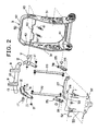
- a vehicle seat 1 in the present invention has a seatback 2, a seat bottom 7, and a headrest 6 provided in an upper part of the seat bottom 7.
- the headrest 6 is movable substantially forward toward a forward head protection position from a normal support position due to a collision load caused by a rear-end collision of a vehicle.
- a seatback frame 3 of the seatback 2 has a pair of side frames 31, an upper connecting frame 40 and a lower connecting frame 41 and shows a rectangular frame form as a whole.
- a cushion 4 is installed on the seatback frame 3 and the front side of the cushion 4 is covered with a skin member 5.
- a headrest supporter 10 that is movable relative to the seatback frame 3 and extends in a lateral direction is arranged in the vicinity of the upper frame 40.
- Vertical engagement parts 9 into which lower parts of pillars 8 of the headrest 6 are inserted are fixed to the supporter 10.
- the headrest 6 is supported freely height-adjustably by the pillars 8 and the vertical engagement parts 9.
- a lengthwise upper link lever 11 is fixed by a pivot 17 in an upper part of each of the side frames 31 (or both sides of the upper frame 40).
- Each end of the headrest supporter 10 is fixed to a connecting part 12 formed in an upper part of the upper link lever 11.
- the supporter 10 is preferably formed from a metal pipe.
- the connecting part 12 is preferably formed in a C-letter shape and has a back plate 14 to support a rear surface part of the supporter 10, a top plate 13 to support a top surface part of the supporter 10, and a bottom plate 15 to support an undersurface of the supporter 10.
- a lower part of the upper link lever 11 is connected to an upper part of a connecting rod 20 by a pin 21.
- a support rod 60 that extends in the lateral direction is arranged between the side frames 31.
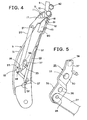
- Upper springs 61 are provided between the support rod 60 and the headrest supporter 10 and the headrest supporter 10 (the headrest 6) is energized toward the rear by elastic force of the upper springs 61 to be maintained in the normal support position. If, however, the upper link lever 11 is rotated counterclockwise around the pivot 17 in FIG. 4 , the headrest supporter 10 is moved forward against the elastic force of the upper springs 61 so that the headrest 6 is pushed forward toward the head protection position.
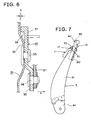
- a flexible cushion plate 50 is arranged inside the seatback frame 3.
- the cushion plate 50 is preferably formed from synthetic resin such as polypropylene and shows a substantially single rectangular plate form.
- the cushion plate 50 is installed on seat springs 52 such as zigzag springs and formed wire springs.
- the seat spring 52 has at least an upper seat spring and a lower seat spring. Each of the seat springs 52 extends substantially in the lateral direction and both ends thereof are connected to the side frames 31, 31 of the seatback frame 3.
- the cushion 4 of the seatback 2 is positioned in front of the cushion plate 50 and supported elastically by the cushion plate 50.
- the cushion plate 50 When the cushion plate 50 receives a normal load from a vehicle seat occupant T through the cushion 4, the cushion plate 50 is moved backward within a predetermined range against elastic force of the springs 52 while being subjected to elastic deformation appropriately to flexibly support the seat occupant T. Because the cushion plate 50 supports the cushion 4 by the "surface", the load of the seat occupant T is distributed and, compared with a conventional structure in which the cushion 4 is supported by the seat springs 52 alone, better stability and comfort are provided to the seat occupant T.
- an upper edge 53 of the cushion plate 50 is positioned slightly above the ninth thoracic vertebrae X of the seat occupant T of an average height.
- the center of gravity of an upper body of the seat occupant T is located around the ninth thoracic vertebrae X.
- the magnitude of movement of the upper body is the least near the ninth thoracic vertebrae X. If the upper edge 53 is positioned above the ninth thoracic vertebrae X, the cushion plate 50 can support movement of many parts of the upper body so that the upper body can effectively be supported.
- the position of the upper edge 53 can be set lower and a wide space part K can thereby be secured between the upper edge 53 and a horizontal pipe frame 42 of the upper frame 40.
- the wide space part K efficiently absorbs energy of backward movement of the upper body (near the thoracic vertebrae) of the seat occupant T when a rear-end collision occurs.
- the wide space part K is made easily securable by making the vertical width of the upper frame 40 smaller, while at the same time securing rigidity of the upper frame 40 by forming the upper frame 40 from a pipe member.
- a collision detector 27 that extends in the lateral direction is arranged between the side frames 31, 31.
- the collision detector 27 is disposed at the rear and in the vicinity of the cushion plate 50. Both sides of the collision detector 27 are respectively connected, by pins 28, 28, to lower links 25, 25 fixed to the side frames 31, 31 by pivots 33, 33.
- a lower part of the connecting rod 20 is connected to the lower link 25 by a pin 26.
- the cushion plate 50 is thereby moved backward exceeding-the predetermined range and then, brought into contact with the collision detector 27 to move the collision detector 27 backward.
- Backward movement of the detector 27 rotates the lower link 25 counterclockwise in FIG. 4 to move the connecting rod 20 downward.
- Downward movement of the connecting rod 20 rotates the upper link lever 11 counterclockwise and the headrest supporter 10 is thereby moved forward to push the headrest 6 forward so that the head (cervical part) of the seat occupant T is protected when a rear-end collision occurs.
- the mechanism to push the headrest 6 forward by backward movement of the collision detector 27 is an active headrest mechanism.
- the lower link 25 is installed on an inside bulged part 32 of the side frame 31 by a pivot 33.
- the lower link 25 has a connecting arm 35 connected to the collision detector 27 and a counter arm 37 extending in the opposite direction of the connecting arm 35.
- the counter arm 37 has a support projection 38 extending toward the side frame 31.
- the connecting arm 35 of the lower link 25 is pulled in the counterclockwise direction in FIG. 4 , but because the gap S is formed between the support projection 38 and the side frame 31, the connecting arm 35 rotates smoothly without extra rotational resistance being applied to the lower link 25 to protect the head (cervical part) of the seat occupant T by pushing the headrest 6 forward.
- the upper frame 40 shows an inverted U-letter shape and has the horizontal pipe frame 42 and vertical pipe frames 43 extending downward from both sides of the pipe frame 42. Lower parts of the vertical pipe frames 43 are superimposed on upper parts of the side frames 31 and then, the superimposed parts are welded for fixing. An important thing is to-fix the vertical pipe frames 43 on top of the left and right side frames 31 to secure the wide space part K.
- Causing the headrest 6 to move forward by an active headrest mechanism when a rear-end collision occurs is extremely effective in protecting the head of a seated person. It is also extremely effective in protecting a seat occupant when a rear-end collision occurs to efficiently support the upper side of the back of the seated person. Thus, when a rear-end collision occurs, it is desirable that the upper side of the back of the seat occupant be deeply absorbed into the seatback 2. To realize absorption of the seated person, it is effective to provide the wide space part K above the seatback frame 3 and in this application, thanks to the wide space part K, the upper side of the back of the seat occupant can deeply be absorbed into the seatback 2 efficiently.
Landscapes
- Engineering & Computer Science (AREA)
- Aviation & Aerospace Engineering (AREA)
- Transportation (AREA)
- Mechanical Engineering (AREA)
- Seats For Vehicles (AREA)
- Chair Legs, Seat Parts, And Backrests (AREA)
Claims (2)
- Siège de véhicule comprenant :un cadre de dossier (3) ;un appui-tête (6) monté sur le cadre de dossier de manière à pouvoir se déplacer dans une direction avant et arrière par un mécanisme d'appui-tête actif ;un détecteur de collision (27) prévu sur le cadre de dossier pour détecter un mouvement vers l'arrière d'une partie lombaire d'un occupant du siège lorsqu'une collision par l'arrière se produit ;dans lequel le détecteur de collision et le mécanisme d'appui-tête actif sont reliés l'un à l'autre au moyen d'un mécanisme de liaison de sorte que l'appui-tête soit déplacé vers l'avant par le mouvement vers l'arrière du détecteur de collision pour supporter la tête de l'occupant du siège ;dans lequel au moins un cadre supérieur (40) du cadre de dossier (3), dans lequel le mécanisme d'appui-tête actif est prévu, est formé à partir d'un élément cylindrique, formant ainsi un espace (K) entouré par le cadre supérieur (40) et des cadres latéraux (31) sur des côtés gauche et droit au-dessus du cadre de dossier (3) ;dans lequel le cadre supérieur (40) présente la forme de la lettre C au moyen d'un cadre tubulaire horizontal (42) et des cadres tubulaires verticaux (43) formés à partir de l'élément cylindrique, et le mécanisme d'appui-tête actif est positionné à l'intérieur de l'espace (K) entouré par le cadre tubulaire horizontal (42) et les cadres tubulaires verticaux du cadre supérieur ayant la forme de la lettre C, des parties inférieures des cadres tubulaires verticaux (43) sur les côtés gauche et droit du cadre supérieur (40) sont superposées sur des parties supérieures des cadres latéraux (31) du cadre de dossier (3) et des parties superposées sont soudées pour la fixation ;caractérisé en ce que le mécanisme d'appui-tête actif comprend un support d'appui-tête (10) dans une direction horizontale sur lequel les éléments de support de piliers destinés à supporter les piliers (8) sont installés et des leviers de liaison supérieurs (11) pour amener le support d'appui-tête à se déplacer vers l'avant par rapport au dossier, chaque levier de liaison supérieur forme d'un seul tenant une partie de liaison en reliant une tige de connexion (20) pour transmettre l'actionnement du détecteur de collision à une partie de connexion (12) présentant la forme de la lettre C par une plaque supérieure (13), une plaque arrière (14), et une plaque inférieure (15), la partie de liaison est installée sur le cadre tubulaire vertical par un pivot (17), et les extrémités du support d'appui-tête formées d'un élément cylindrique sont ajustées dans un espace de la partie de connexion (12) entouré par la plaque supérieure (13), la plaque arrière (14), et la plaque inférieure (15).
- Siège de véhicule selon la revendication 1, dans lequel une plaque de coussin en forme de plaque unique (50) qui est séparée du détecteur de collision (27) et qui peut supporter le dos de l'occupant du siège, est installée à l'intérieur d'un cadre rectangulaire creux du cadre de dossier (3) de manière à pouvoir se déplacer librement dans la direction longitudinale par rapport au cadre de dossier par l'intermédiaire de ressorts de siège (52), le détecteur de collision (27) est prévu dans une partie arrière de la plaque de coussin (50), et un bord supérieur de la plaque de coussin est positionné au moins au-dessus de la neuvième vertèbre thoracique X d'un occupant du siège T de taille moyenne pour former un espace (K) aussi large que possible entre le bord supérieur de la plaque de coussin et le cadre supérieur.
Applications Claiming Priority (3)
| Application Number | Priority Date | Filing Date | Title |
|---|---|---|---|
| JP2006155458A JP4931479B2 (ja) | 2006-06-02 | 2006-06-02 | 車両用シート |
| JP2006155457A JP2007320506A (ja) | 2006-06-02 | 2006-06-02 | 車両用シート |
| PCT/JP2007/061228 WO2007142162A1 (fr) | 2006-06-02 | 2007-06-02 | Siège de véhicule |
Publications (3)
| Publication Number | Publication Date |
|---|---|
| EP2030835A1 EP2030835A1 (fr) | 2009-03-04 |
| EP2030835A4 EP2030835A4 (fr) | 2010-01-20 |
| EP2030835B1 true EP2030835B1 (fr) | 2014-05-21 |
Family
ID=38801417
Family Applications (1)
| Application Number | Title | Priority Date | Filing Date |
|---|---|---|---|
| EP07744615.1A Not-in-force EP2030835B1 (fr) | 2006-06-02 | 2007-06-02 | Siège de véhicule |
Country Status (3)
| Country | Link |
|---|---|
| US (1) | US8113578B2 (fr) |
| EP (1) | EP2030835B1 (fr) |
| WO (1) | WO2007142162A1 (fr) |
Families Citing this family (10)
| Publication number | Priority date | Publication date | Assignee | Title |
|---|---|---|---|---|
| US7644987B2 (en) | 2004-09-27 | 2010-01-12 | Lear Corporation | Vehicle seat having active head restraint system |
| JP5091574B2 (ja) * | 2007-07-19 | 2012-12-05 | テイ・エス テック株式会社 | 車両用シート |
| US8632126B2 (en) | 2009-01-21 | 2014-01-21 | Ts Tech Co., Ltd. | Vehicle seat |
| US8544948B2 (en) * | 2009-01-21 | 2013-10-01 | Ts Tech Co., Ltd. | Vehicle seat |
| JP5802368B2 (ja) * | 2010-07-21 | 2015-10-28 | テイ・エス テック株式会社 | 乗物用シート |
| WO2012011542A1 (fr) * | 2010-07-21 | 2012-01-26 | テイ・エス テック株式会社 | Siège de véhicule |
| WO2012086364A1 (fr) * | 2010-12-24 | 2012-06-28 | 本田技研工業株式会社 | Structure de dossier de siège de véhicule |
| WO2014024585A1 (fr) * | 2012-08-07 | 2014-02-13 | テイ・エス テック株式会社 | Siège de véhicule |
| WO2014024586A1 (fr) * | 2012-08-07 | 2014-02-13 | テイ・エス テック株式会社 | Siège de véhicule |
| JP5940479B2 (ja) * | 2013-03-12 | 2016-06-29 | 株式会社タチエス | 車両用シートのシートバック |
Citations (1)
| Publication number | Priority date | Publication date | Assignee | Title |
|---|---|---|---|---|
| JP2006020733A (ja) * | 2004-07-06 | 2006-01-26 | T S Tec Kk | 車両用シート |
Family Cites Families (10)
| Publication number | Priority date | Publication date | Assignee | Title |
|---|---|---|---|---|
| DE19752247C2 (de) * | 1997-11-26 | 2000-02-17 | Faure Bertrand Sitztech Gmbh | Rückenlehne eines Fahrzeugsitzes mit einer Kopfstützen-Anordnung |
| US6523892B1 (en) * | 1999-05-20 | 2003-02-25 | Mazda Motor Corporation | Seat structure for vehicle |
| JP3783225B2 (ja) | 1999-05-20 | 2006-06-07 | マツダ株式会社 | 車両用シート構造 |
| JP3973936B2 (ja) * | 2002-03-19 | 2007-09-12 | ダイハツ工業株式会社 | 自動車用シート |
| US6837541B2 (en) * | 2002-09-30 | 2005-01-04 | Lear Corporation | Vehicle seat having a lumbar support system |
| US6779840B1 (en) * | 2003-08-27 | 2004-08-24 | Lear Corporation | Locking and unlocking mechanism for an active headrest for a vehicle seat |
| JP4118256B2 (ja) * | 2004-06-22 | 2008-07-16 | トヨタ自動車株式会社 | 車両用シート |
| JP4815111B2 (ja) * | 2004-08-19 | 2011-11-16 | 日本発條株式会社 | 車両用シート |
| US7044544B2 (en) * | 2004-09-27 | 2006-05-16 | Lear Corporation | Vehicle seat assembly having active head restraint system |
| JP4737501B2 (ja) * | 2004-10-28 | 2011-08-03 | テイ・エス テック株式会社 | 車両用シート |
-
2007
- 2007-06-02 US US12/303,204 patent/US8113578B2/en not_active Expired - Fee Related
- 2007-06-02 EP EP07744615.1A patent/EP2030835B1/fr not_active Not-in-force
- 2007-06-02 WO PCT/JP2007/061228 patent/WO2007142162A1/fr not_active Ceased
Patent Citations (1)
| Publication number | Priority date | Publication date | Assignee | Title |
|---|---|---|---|---|
| JP2006020733A (ja) * | 2004-07-06 | 2006-01-26 | T S Tec Kk | 車両用シート |
Also Published As
| Publication number | Publication date |
|---|---|
| US20100060047A1 (en) | 2010-03-11 |
| EP2030835A1 (fr) | 2009-03-04 |
| EP2030835A4 (fr) | 2010-01-20 |
| US8113578B2 (en) | 2012-02-14 |
| WO2007142162A1 (fr) | 2007-12-13 |
Similar Documents
| Publication | Publication Date | Title |
|---|---|---|
| EP2030835B1 (fr) | Siège de véhicule | |
| JP4737501B2 (ja) | 車両用シート | |
| EP1908628B1 (fr) | Siège de véhicule et procédé d assemblage de siège de véhicule | |
| US8210607B2 (en) | Vehicle seat | |
| JP5481866B2 (ja) | アクティブヘッドレストを組み付けたシートバックの内部構造 | |
| JP4737508B2 (ja) | 車両用シート | |
| EP1842717B1 (fr) | Mecanisme d'appui-tete pour siege de vehicule | |
| WO2015033971A1 (fr) | Cadre de dossier de siège | |
| JP4728670B2 (ja) | 自動車用シートのバックレストフレーム | |
| CN102069735B (zh) | 车辆用椅 | |
| JP4640969B2 (ja) | 車両用シートおよび車両用シートの組立方法 | |
| JP4450316B2 (ja) | 車両用シート | |
| JP2007320506A (ja) | 車両用シート | |
| JP7364852B2 (ja) | 乗物用シート | |
| JP7364848B2 (ja) | 乗物用シート | |
| JP4492863B2 (ja) | 車両用シート | |
| JP5229524B2 (ja) | 車両のシート構造 | |
| JP4488854B2 (ja) | 車両用シート | |
| JP4737509B2 (ja) | 車両用シート | |
| JP4492871B2 (ja) | 車両用シート | |
| JP5099662B2 (ja) | 車両用シート | |
| JP2007290454A (ja) | 車両用シート | |
| JP4931479B2 (ja) | 車両用シート | |
| JP6439567B2 (ja) | 乗物用シート | |
| JP5044156B2 (ja) | ヘッドレストを備えた車両用シート |
Legal Events
| Date | Code | Title | Description |
|---|---|---|---|
| PUAI | Public reference made under article 153(3) epc to a published international application that has entered the european phase |
Free format text: ORIGINAL CODE: 0009012 |
|
| 17P | Request for examination filed |
Effective date: 20090108 |
|
| AK | Designated contracting states |
Kind code of ref document: A1 Designated state(s): AT BE BG CH CY CZ DE DK EE ES FI FR GB GR HU IE IS IT LI LT LU LV MC MT NL PL PT RO SE SI SK TR |
|
| AX | Request for extension of the european patent |
Extension state: AL BA HR MK RS |
|
| A4 | Supplementary search report drawn up and despatched |
Effective date: 20091223 |
|
| R17P | Request for examination filed (corrected) |
Effective date: 20090108 |
|
| 17Q | First examination report despatched |
Effective date: 20100413 |
|
| DAX | Request for extension of the european patent (deleted) | ||
| GRAP | Despatch of communication of intention to grant a patent |
Free format text: ORIGINAL CODE: EPIDOSNIGR1 |
|
| INTG | Intention to grant announced |
Effective date: 20131209 |
|
| GRAS | Grant fee paid |
Free format text: ORIGINAL CODE: EPIDOSNIGR3 |
|
| GRAA | (expected) grant |
Free format text: ORIGINAL CODE: 0009210 |
|
| AK | Designated contracting states |
Kind code of ref document: B1 Designated state(s): AT BE BG CH CY CZ DE DK EE ES FI FR GB GR HU IE IS IT LI LT LU LV MC MT NL PL PT RO SE SI SK TR |
|
| REG | Reference to a national code |
Ref country code: GB Ref legal event code: FG4D |
|
| REG | Reference to a national code |
Ref country code: CH Ref legal event code: EP |
|
| REG | Reference to a national code |
Ref country code: AT Ref legal event code: REF Ref document number: 669417 Country of ref document: AT Kind code of ref document: T Effective date: 20140615 |
|
| REG | Reference to a national code |
Ref country code: IE Ref legal event code: FG4D |
|
| REG | Reference to a national code |
Ref country code: DE Ref legal event code: R096 Ref document number: 602007036851 Country of ref document: DE Effective date: 20140626 |
|
| PGFP | Annual fee paid to national office [announced via postgrant information from national office to epo] |
Ref country code: GB Payment date: 20140606 Year of fee payment: 8 |
|
| REG | Reference to a national code |
Ref country code: NL Ref legal event code: VDEP Effective date: 20140521 Ref country code: AT Ref legal event code: MK05 Ref document number: 669417 Country of ref document: AT Kind code of ref document: T Effective date: 20140521 |
|
| REG | Reference to a national code |
Ref country code: LT Ref legal event code: MG4D |
|
| PG25 | Lapsed in a contracting state [announced via postgrant information from national office to epo] |
Ref country code: IS Free format text: LAPSE BECAUSE OF FAILURE TO SUBMIT A TRANSLATION OF THE DESCRIPTION OR TO PAY THE FEE WITHIN THE PRESCRIBED TIME-LIMIT Effective date: 20140921 Ref country code: FI Free format text: LAPSE BECAUSE OF FAILURE TO SUBMIT A TRANSLATION OF THE DESCRIPTION OR TO PAY THE FEE WITHIN THE PRESCRIBED TIME-LIMIT Effective date: 20140521 Ref country code: GR Free format text: LAPSE BECAUSE OF FAILURE TO SUBMIT A TRANSLATION OF THE DESCRIPTION OR TO PAY THE FEE WITHIN THE PRESCRIBED TIME-LIMIT Effective date: 20140822 Ref country code: LT Free format text: LAPSE BECAUSE OF FAILURE TO SUBMIT A TRANSLATION OF THE DESCRIPTION OR TO PAY THE FEE WITHIN THE PRESCRIBED TIME-LIMIT Effective date: 20140521 |
|
| PGFP | Annual fee paid to national office [announced via postgrant information from national office to epo] |
Ref country code: DE Payment date: 20140827 Year of fee payment: 8 |
|
| PG25 | Lapsed in a contracting state [announced via postgrant information from national office to epo] |
Ref country code: PL Free format text: LAPSE BECAUSE OF FAILURE TO SUBMIT A TRANSLATION OF THE DESCRIPTION OR TO PAY THE FEE WITHIN THE PRESCRIBED TIME-LIMIT Effective date: 20140521 Ref country code: AT Free format text: LAPSE BECAUSE OF FAILURE TO SUBMIT A TRANSLATION OF THE DESCRIPTION OR TO PAY THE FEE WITHIN THE PRESCRIBED TIME-LIMIT Effective date: 20140521 Ref country code: SE Free format text: LAPSE BECAUSE OF FAILURE TO SUBMIT A TRANSLATION OF THE DESCRIPTION OR TO PAY THE FEE WITHIN THE PRESCRIBED TIME-LIMIT Effective date: 20140521 Ref country code: LV Free format text: LAPSE BECAUSE OF FAILURE TO SUBMIT A TRANSLATION OF THE DESCRIPTION OR TO PAY THE FEE WITHIN THE PRESCRIBED TIME-LIMIT Effective date: 20140521 Ref country code: ES Free format text: LAPSE BECAUSE OF FAILURE TO SUBMIT A TRANSLATION OF THE DESCRIPTION OR TO PAY THE FEE WITHIN THE PRESCRIBED TIME-LIMIT Effective date: 20140521 |
|
| PGFP | Annual fee paid to national office [announced via postgrant information from national office to epo] |
Ref country code: FR Payment date: 20140626 Year of fee payment: 8 |
|
| PG25 | Lapsed in a contracting state [announced via postgrant information from national office to epo] |
Ref country code: PT Free format text: LAPSE BECAUSE OF FAILURE TO SUBMIT A TRANSLATION OF THE DESCRIPTION OR TO PAY THE FEE WITHIN THE PRESCRIBED TIME-LIMIT Effective date: 20140922 |
|
| PG25 | Lapsed in a contracting state [announced via postgrant information from national office to epo] |
Ref country code: CZ Free format text: LAPSE BECAUSE OF FAILURE TO SUBMIT A TRANSLATION OF THE DESCRIPTION OR TO PAY THE FEE WITHIN THE PRESCRIBED TIME-LIMIT Effective date: 20140521 Ref country code: SK Free format text: LAPSE BECAUSE OF FAILURE TO SUBMIT A TRANSLATION OF THE DESCRIPTION OR TO PAY THE FEE WITHIN THE PRESCRIBED TIME-LIMIT Effective date: 20140521 Ref country code: DK Free format text: LAPSE BECAUSE OF FAILURE TO SUBMIT A TRANSLATION OF THE DESCRIPTION OR TO PAY THE FEE WITHIN THE PRESCRIBED TIME-LIMIT Effective date: 20140521 Ref country code: EE Free format text: LAPSE BECAUSE OF FAILURE TO SUBMIT A TRANSLATION OF THE DESCRIPTION OR TO PAY THE FEE WITHIN THE PRESCRIBED TIME-LIMIT Effective date: 20140521 Ref country code: RO Free format text: LAPSE BECAUSE OF FAILURE TO SUBMIT A TRANSLATION OF THE DESCRIPTION OR TO PAY THE FEE WITHIN THE PRESCRIBED TIME-LIMIT Effective date: 20140521 Ref country code: BE Free format text: LAPSE BECAUSE OF FAILURE TO SUBMIT A TRANSLATION OF THE DESCRIPTION OR TO PAY THE FEE WITHIN THE PRESCRIBED TIME-LIMIT Effective date: 20140521 |
|
| REG | Reference to a national code |
Ref country code: CH Ref legal event code: PL |
|
| REG | Reference to a national code |
Ref country code: DE Ref legal event code: R097 Ref document number: 602007036851 Country of ref document: DE |
|
| PG25 | Lapsed in a contracting state [announced via postgrant information from national office to epo] |
Ref country code: NL Free format text: LAPSE BECAUSE OF FAILURE TO SUBMIT A TRANSLATION OF THE DESCRIPTION OR TO PAY THE FEE WITHIN THE PRESCRIBED TIME-LIMIT Effective date: 20140521 |
|
| REG | Reference to a national code |
Ref country code: IE Ref legal event code: MM4A |
|
| PLBE | No opposition filed within time limit |
Free format text: ORIGINAL CODE: 0009261 |
|
| STAA | Information on the status of an ep patent application or granted ep patent |
Free format text: STATUS: NO OPPOSITION FILED WITHIN TIME LIMIT |
|
| 26N | No opposition filed |
Effective date: 20150224 |
|
| PG25 | Lapsed in a contracting state [announced via postgrant information from national office to epo] |
Ref country code: LI Free format text: LAPSE BECAUSE OF NON-PAYMENT OF DUE FEES Effective date: 20140630 Ref country code: IT Free format text: LAPSE BECAUSE OF FAILURE TO SUBMIT A TRANSLATION OF THE DESCRIPTION OR TO PAY THE FEE WITHIN THE PRESCRIBED TIME-LIMIT Effective date: 20140521 Ref country code: IE Free format text: LAPSE BECAUSE OF NON-PAYMENT OF DUE FEES Effective date: 20140602 Ref country code: CH Free format text: LAPSE BECAUSE OF NON-PAYMENT OF DUE FEES Effective date: 20140630 |
|
| REG | Reference to a national code |
Ref country code: DE Ref legal event code: R097 Ref document number: 602007036851 Country of ref document: DE Effective date: 20150224 |
|
| PG25 | Lapsed in a contracting state [announced via postgrant information from national office to epo] |
Ref country code: SI Free format text: LAPSE BECAUSE OF FAILURE TO SUBMIT A TRANSLATION OF THE DESCRIPTION OR TO PAY THE FEE WITHIN THE PRESCRIBED TIME-LIMIT Effective date: 20140521 |
|
| REG | Reference to a national code |
Ref country code: DE Ref legal event code: R119 Ref document number: 602007036851 Country of ref document: DE |
|
| GBPC | Gb: european patent ceased through non-payment of renewal fee |
Effective date: 20150602 |
|
| PG25 | Lapsed in a contracting state [announced via postgrant information from national office to epo] |
Ref country code: MT Free format text: LAPSE BECAUSE OF FAILURE TO SUBMIT A TRANSLATION OF THE DESCRIPTION OR TO PAY THE FEE WITHIN THE PRESCRIBED TIME-LIMIT Effective date: 20140521 |
|
| REG | Reference to a national code |
Ref country code: FR Ref legal event code: ST Effective date: 20160229 |
|
| PG25 | Lapsed in a contracting state [announced via postgrant information from national office to epo] |
Ref country code: GB Free format text: LAPSE BECAUSE OF NON-PAYMENT OF DUE FEES Effective date: 20150602 Ref country code: MC Free format text: LAPSE BECAUSE OF FAILURE TO SUBMIT A TRANSLATION OF THE DESCRIPTION OR TO PAY THE FEE WITHIN THE PRESCRIBED TIME-LIMIT Effective date: 20140521 Ref country code: DE Free format text: LAPSE BECAUSE OF NON-PAYMENT OF DUE FEES Effective date: 20160101 |
|
| PG25 | Lapsed in a contracting state [announced via postgrant information from national office to epo] |
Ref country code: BG Free format text: LAPSE BECAUSE OF FAILURE TO SUBMIT A TRANSLATION OF THE DESCRIPTION OR TO PAY THE FEE WITHIN THE PRESCRIBED TIME-LIMIT Effective date: 20140521 Ref country code: FR Free format text: LAPSE BECAUSE OF NON-PAYMENT OF DUE FEES Effective date: 20150630 |
|
| PG25 | Lapsed in a contracting state [announced via postgrant information from national office to epo] |
Ref country code: CY Free format text: LAPSE BECAUSE OF FAILURE TO SUBMIT A TRANSLATION OF THE DESCRIPTION OR TO PAY THE FEE WITHIN THE PRESCRIBED TIME-LIMIT Effective date: 20140521 |
|
| PG25 | Lapsed in a contracting state [announced via postgrant information from national office to epo] |
Ref country code: TR Free format text: LAPSE BECAUSE OF FAILURE TO SUBMIT A TRANSLATION OF THE DESCRIPTION OR TO PAY THE FEE WITHIN THE PRESCRIBED TIME-LIMIT Effective date: 20140521 Ref country code: HU Free format text: LAPSE BECAUSE OF FAILURE TO SUBMIT A TRANSLATION OF THE DESCRIPTION OR TO PAY THE FEE WITHIN THE PRESCRIBED TIME-LIMIT; INVALID AB INITIO Effective date: 20070602 Ref country code: LU Free format text: LAPSE BECAUSE OF NON-PAYMENT OF DUE FEES Effective date: 20140602 |