EP2030855A2 - Véhicule sur rail et procédé de vérification de l'efficacité d'un frein mécanique du véhicule sur rail - Google Patents
Véhicule sur rail et procédé de vérification de l'efficacité d'un frein mécanique du véhicule sur rail Download PDFInfo
- Publication number
- EP2030855A2 EP2030855A2 EP08075736A EP08075736A EP2030855A2 EP 2030855 A2 EP2030855 A2 EP 2030855A2 EP 08075736 A EP08075736 A EP 08075736A EP 08075736 A EP08075736 A EP 08075736A EP 2030855 A2 EP2030855 A2 EP 2030855A2
- Authority
- EP
- European Patent Office
- Prior art keywords
- mechanical brake
- rail vehicle
- speed
- test
- brake
- Prior art date
- Legal status (The legal status is an assumption and is not a legal conclusion. Google has not performed a legal analysis and makes no representation as to the accuracy of the status listed.)
- Granted
Links
Images

Classifications
-
- B—PERFORMING OPERATIONS; TRANSPORTING
- B60—VEHICLES IN GENERAL
- B60T—VEHICLE BRAKE CONTROL SYSTEMS OR PARTS THEREOF; BRAKE CONTROL SYSTEMS OR PARTS THEREOF, IN GENERAL; ARRANGEMENT OF BRAKING ELEMENTS ON VEHICLES IN GENERAL; PORTABLE DEVICES FOR PREVENTING UNWANTED MOVEMENT OF VEHICLES; VEHICLE MODIFICATIONS TO FACILITATE COOLING OF BRAKES
- B60T17/00—Component parts, details, or accessories of power brake systems not covered by groups B60T8/00, B60T13/00 or B60T15/00, or presenting other characteristic features
- B60T17/18—Safety devices; Monitoring
- B60T17/22—Devices for monitoring or checking brake systems; Signal devices
- B60T17/228—Devices for monitoring or checking brake systems; Signal devices for railway vehicles
Definitions
- the invention relates to a method for testing the effectiveness of a mechanical brake of a rail vehicle, in particular a light rail vehicle, such as e.g. a tram.
- the invention further relates to a rail vehicle, in particular a light rail vehicle.
- the effectiveness of the mechanical brake or mechanical brakes should be checked frequently.
- the effectiveness of the mechanical brake is a function of the brake pressure (of the hydraulic or pneumatic system), the settings (e.g., pad clearance) and the wear of the brake pads. It is customary to perform the prescribed test, in particular the brake pads by a visual inspection. For this purpose, the vehicle is driven over an inspection pit, so that a mechanic or the driver can look at the brake pads.
- the effort for testing the effectiveness should be reduced.
- a corresponding rail vehicle to be specified.
- the present invention is based on the following idea: In modern rail vehicles, e.g. driven by three-phase AC motors, the drive power or the braking force of the motors can be accurately calculated from electrical quantities. The calculated tensile force should therefore be used to determine the effectiveness of the mechanical brake or the mechanical brakes.
- rail vehicles have a speed control which is able to achieve and maintain a predetermined speed (this is understood here as the speed amount) of the rail vehicle.
- a phase in which the speed is kept constant can be described as the stationary phase or steady state or steady state of the Speed control are called.
- the driver of the rail vehicle sets a specific speed value on the driver's cab as a setpoint.
- the cruise control then increases or decreases the speed by changing the pulling or braking force until the setpoint is reached. Thereafter, the cruise control controls the traction motors so that any existing driving resistance is compensated or a speed, for example, occurring in the downhill or uphill is compensated by means of tension change.
- the drive traction can be determined, for example, from the motor current and excitation current and speed.
- the torque is calculated by a controller of the rail vehicle drive motor.
- the product is formed from stator flux to stator current.
- the stator flux is equal to the fundamental voltage divided by the fundamental frequency f1: 4 / Pi * Ud * A / 2 * Pi * f1.
- Ud are the DC voltage on a DC side of an inverter, which supplies the drive motor with alternating current
- A is the modulation of the inverter.
- the stator flux is formed in a computer model of the motor by integration of the switched voltage, in particular by multiplying the voltage with time. Since the DC voltage (usually the DC link voltage of a DC link on the DC side of the inverter) is accurately known, the stator flux can be calculated with high accuracy, except while the rail vehicle is starting.
- the stator current is measured with current sensors and is usually known with an accuracy of 1%. It follows that the torque and thus the tensile force can be calculated with a relative error of a few percent.
- the braking force when the mechanical brake is not actuated can also be calculated, for example, by measuring the deceleration of the rail vehicle.
- the braking force is equal to the decelerated mass times the deceleration.
- the braking energy is obtained by multiplying by the braking distance, wherein, if necessary, the time integral over the deceleration process is to be calculated when the delay is changing with time.
- the braking power is calculated from the braking energy divided by the delay time.
- a rail vehicle is proposed with an automatic cruise control and with a test device for testing the effectiveness of a mechanical brake of the rail vehicle, wherein the test device is designed, during a drive of the rail vehicle at a constant speed when the mechanical brake is actuated, one of the automatic cruise control of the rail vehicle caused increased driving force to determine and determine the effectiveness of the mechanical brake from the increased driving force.
- the additionally required tractive force which the speed controller adjusts corresponds to the effect of the mechanical brake to be tested.
- the braking force of the mechanical brake is mentioned, this also includes the case that e.g. over a defined time or distance the braking energy of the mechanical brake is determined. Also from this, the effectiveness of the mechanical brake can be determined. The same applies to the drive power.
- the effectiveness of the mechanical brake is maintained at constant low speeds, e.g. tested in the speed range of 3 to 20 km / h.
- the effectiveness of the mechanical brake is preferably tested in a range in which the inclination of the test track does not change and also a curve radius of a possibly existing curve of the route does not change.
- the test takes place in a straight stretch of road.
- the test is initiated by the fact that after reaching the steady state of the speed control, preferably when driving straight ahead and at a constant slope of the route, first required for the maintenance of the steady state driving force (or drive power) or electric braking force (braking power or braking energy ) is determined, in particular by performing electrical measurements as mentioned above. Subsequently, the mechanical brake or preferably each one after the other, all mechanical brakes can be actuated and can again (preferably individually for the brakes) the driving force (or drive power or drive energy) are measured. The driving force or braking force determined prior to the actuation of the mechanical brake (s) then serves to calculate the additional driving force (drive power) applied when the mechanical brake (s) is actuated.
- the brake test is repeated under the same conditions in any of the embodiments described in this specification.
- the conditions relate in particular to the inclination of the route on which the brake test is performed, the specification of a desired braking effect, the driving speed and / or the operating mode of the drive system (in particular, the operating mode is understood to mean that the electric traction motors of the rail vehicle in the same way operate). If the conditions are identical, it can be concluded from the repetition of the brake test directly to a decrease in the braking force of the mechanical brake (s) when compared to a previous brake test, a smaller increase in the driving force is sufficient, ie setting the same desired braking force as in the previous test does not lead to the same braking effect.
- This embodiment has the advantage that the increased driving force (or driving power) need not be explicitly determined. Rather, it is sufficient to note in the various repetitions of the test (at least one repetition) that either the same or (with reduced braking power) a lower drive force increase was necessary compared to the previous test or tests (with unchanged braking power).
- the invention has the advantage that the driver can check the state of the mechanical brakes in suitable operating phases without having to interrupt the actual driving operation of the vehicle.
- the brake test can also be carried out during normal driving without the driver being distracted.
- the driver can be notified.
- this information can also be transmitted to the control center or be transmitted to the built-in diagnostic system.
- Modern existing rail vehicles have a control computer for controlling the essential vehicle functions, in particular the drives and the brakes of the vehicle. It is therefore possible in a simple manner, namely by changing the software of the computer to extend existing rail vehicles to the inventive test function.
- the invention is not limited to such retrofitting.
- a computer can be installed in the rail vehicle and the testing of the effectiveness of the mechanical brake (s) can be done by software and / or hardware.
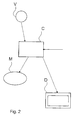
- V denotes a speed measuring device which generates a measured value for the current vehicle speed and transmits it to a controller C.
- the controller C is, for example, the drive control, in which, however, also other functions can be integrated, such as monitoring functions that are performed for the safe and reliable operation of the vehicle.
- the traction motor M which drives the rail vehicle, is controlled by the controller C.
- the unit M is to be understood schematically and contains in particular one or more traction motors and one or more corresponding electrical devices, such as inverters, which provide the motor current.
- the instantaneous driving force or drive power can also be accurately calculated from the measurement of the electrical quantities.
- the controller C receives, as indicated by an arrow pointing from right to left on the control C arrow, also a target value for a driving speed of the vehicle.
- the setpoint is set by a corresponding operator action of the vehicle driver.
- the controller C is connected to a display device D which may be e.g. can be a display and / or signal lights.
- a display device D which may be e.g. can be a display and / or signal lights.
- the driver initiates the testing of the mechanical brake (s) by issuing a corresponding command thereto.
- the test it is also possible for the test to be performed automatically under suitable test conditions (e.g., slow steady speed ride on flat terrain when driving straight ahead).
- step S1 the test is initialized.
- step S2 a standby state is reached. This means, in particular, that the software evaluates information as to whether suitable test conditions exist for carrying out the test of the mechanical brake (s).
- step S3 suitable conditions for carrying out the test are now available.
- the vehicle is moving at a constant slow speed, eg at 5 km / h, and the track has a constant slope, eg 1% slope, 1% slope or is in the plane.
- the automatic speed control eg in the control device C according to FIG Fig. 2 integrated
- the automatic cruise control will therefore compensate for any changing driving resistances by increasing or decreasing the driving force. This is exactly what will happen after reaching the standby state in which the test can begin (step S4), and after the actual start of the test (eg by the driver, step S5) used to determine the braking force of the mechanical brakes of the vehicle.
- step S6 first the first of the total (in our example) four mechanical brakes of the vehicle is controlled with a reproducible setpoint of the mechanical braking force.
- the setpoint may be e.g. also be a specification of a certain brake pressure of a pneumatic or hydraulic brake system or a control value of a control device.
- a mechanical brake setpoint can be specified, this then tries to implement.
- the brake pressure or mechanical control value is converted depending on the efficiency of the brake in various actual braking forces.
- step S7 the braking force of the mechanical brake is determined.
- step S7 the result is stored and it can optionally be already determined whether the braking effect of the first mechanical brake meets expectations, does not meet or to what extent it deviates from expectations. However, this evaluation can also be carried out only in step S14 or in a subsequent step, not shown.
- step S8 following step S7, the second mechanical brake is now actuated and the required driving force is measured in order to maintain the constant speed of the vehicle.
- the evaluation of the test of the second mechanical brake is analogous to step S7 in step S9.
- the steps S10 and S11 and the steps S12 and S13 similarly apply to the third mechanical brake and the fourth mechanical brake of the vehicle.
- step S14 following step S13, the data obtained in the mechanical brake test is saved, e.g. stored in a data store. This makes it possible, in particular later, to evaluate the history of different tests carried out at intervals with respect to one another.
- the evaluation of the braking effect of the mechanical brakes can also be based on the measured drive powers during the actuation of the brakes.
- Step S14 is followed by e.g. step S3 again if the conditions for performing the test need to be rechecked.
- step S2 may also be followed by step S2 if the conditions are no longer present, e.g. no constant speed can or will be driven anymore. If the test conditions are present, step S14 can also be followed by step S4, so that the system is again ready for the start of the test by step S5.
- test can also be canceled at any time and the rail vehicle goes immediately to the normal state.
- the desired braking value is kept constant over time during the actuation of one of the mechanical brakes. This facilitates the evaluation.
- the additional drive force during the actuation of the mechanical brake is proportional to the effectiveness of the mechanical brake. This makes it possible, for example, to set a limit value for the additional driving force, which must be exceeded when specifying a specific setpoint braking value. If the limit is not exceeded, a corresponding message can be generated, eg on the display device D according to Fig. 2 being represented. The braking effect is too small in this case.
- the test of the mechanical brake (s) may be stopped at any time by the driver, e.g. if the driving situation requires it.
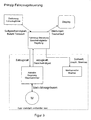
- the course of the test procedure is also off in a variant FIG. 3 seen.
- the driver gives z.
- it may command to start the test, and may also preferentially set the target speed (constant vehicle speed during the test) at which the test is to be performed.
- the vehicle control which also includes a means for controlling the speed to a constant value, receives the command to start the test. It now specifies for carrying out the test and in particular for achieving and / or maintaining the vehicle speed, a desired tensile force, which is transmitted in the embodiment of the drive control of a drive motor M.
- the drive control is in the embodiment, a control of a 3-phase inverter for driving a three-phase motor M.
- the drive control corresponding measured variables are supplied in particular via the flowing electric motor currents, the DC voltage at the inverter and the speed from which the drive control can determine the actual tensile force (actual tractive force) and the speed of the vehicle. These two quantities are transmitted to the cruise control of the vehicle control.
- the vehicle control also adjusts the mechanical brake, transmitting a setpoint of the braking force defined by it to the brake system.
- the vehicle controller may include a plurality of outputs and inputs through which the desired tractive effort, the actual tractive effort, the speed and the desired value of the respective mechanical brake is transmitted.
- a display is connected to the vehicle control in the embodiment, over which the test history and the results of the test can be displayed.
- the sequence is preferably realized with a sequential control which sequentially controls the individual test steps.
Landscapes
- Engineering & Computer Science (AREA)
- Transportation (AREA)
- Mechanical Engineering (AREA)
- Electric Propulsion And Braking For Vehicles (AREA)
- Regulating Braking Force (AREA)
- Vehicle Cleaning, Maintenance, Repair, Refitting, And Outriggers (AREA)
- Automobile Manufacture Line, Endless Track Vehicle, Trailer (AREA)
- Control Of Vehicle Engines Or Engines For Specific Uses (AREA)
Applications Claiming Priority (1)
| Application Number | Priority Date | Filing Date | Title |
|---|---|---|---|
| DE102007041235A DE102007041235A1 (de) | 2007-08-30 | 2007-08-30 | Schienenfahrzeug und Verfahren zum Prüfen der Wirksamkeit einer mechanischen Bremse des Schienenfahrzeugs |
Publications (3)
| Publication Number | Publication Date |
|---|---|
| EP2030855A2 true EP2030855A2 (fr) | 2009-03-04 |
| EP2030855A3 EP2030855A3 (fr) | 2010-08-04 |
| EP2030855B1 EP2030855B1 (fr) | 2011-03-02 |
Family
ID=40134741
Family Applications (1)
| Application Number | Title | Priority Date | Filing Date |
|---|---|---|---|
| EP08075736A Active EP2030855B1 (fr) | 2007-08-30 | 2008-08-28 | Véhicule sur rail et procédé de vérification de l'efficacité d'un frein mécanique du véhicule sur rail |
Country Status (4)
| Country | Link |
|---|---|
| EP (1) | EP2030855B1 (fr) |
| AT (1) | ATE500106T1 (fr) |
| DE (2) | DE102007041235A1 (fr) |
| ES (1) | ES2360485T3 (fr) |
Cited By (6)
| Publication number | Priority date | Publication date | Assignee | Title |
|---|---|---|---|---|
| WO2011113566A3 (fr) * | 2010-03-17 | 2012-08-30 | Sew-Eurodrive Gmbh & Co. Kg | Procédé d'exploitation d'un système d'entraînement et système d'entraînement |
| DE102011113083A1 (de) * | 2011-09-09 | 2013-03-14 | Knorr-Bremse Systeme für Schienenfahrzeuge GmbH | Bremssteuereinrichtung für eine Bremsanlage eines Schienenfahrzeuges, Bremsanlage, Schienenfahrzeug und Verfahren zum Durchführen einer Funktionsdiagnose |
| WO2013135393A3 (fr) * | 2012-03-15 | 2013-11-07 | Knorr-Bremse Systeme für Schienenfahrzeuge GmbH | Procédé de commande d'un système d'entraînement et de freinage d'un véhicule, comportant un frein à friction |
| WO2018050391A1 (fr) * | 2016-09-14 | 2018-03-22 | Knorr-Bremse Systeme für Schienenfahrzeuge GmbH | Dispositif de commande de freins et procédé de commande d'un système de freins d'un véhicule ferroviaire |
| WO2021144436A1 (fr) * | 2020-01-17 | 2021-07-22 | Mtu Friedrichshafen Gmbh | Procédé pour surveiller l'aptitude à fonctionner d'un véhicule, commande pour une transmission d'un véhicule, transmission dotée d'une telle commande et véhicule équipé d'une telle transmission |
| IT202000031898A1 (it) * | 2020-12-22 | 2022-06-22 | Faiveley Transport Italia Spa | Procedimento e sistema per la verifica di funzionamento di mezzi di frenatura di almeno un veicolo ferroviario, e sistema per la misurazione di forza di attrito |
Families Citing this family (1)
| Publication number | Priority date | Publication date | Assignee | Title |
|---|---|---|---|---|
| NO2785692T3 (fr) * | 2014-08-06 | 2018-02-24 |
Family Cites Families (3)
| Publication number | Priority date | Publication date | Assignee | Title |
|---|---|---|---|---|
| JPH03118439A (ja) * | 1989-10-02 | 1991-05-21 | Meidensha Corp | パワートレイン試験設備における制動方式 |
| DE19755112B4 (de) * | 1996-12-21 | 2007-06-28 | Volkswagen Ag | Verfahren und Überwachungsvorrichtung zum Feststellen eines Nachlassens der Bremswirkung einer Kraftfahrzeugbremse |
| DE10337815A1 (de) * | 2003-08-14 | 2005-03-24 | Rwe Rheinbraun Ag | Verfahren zur Prüfung von pneumatischen und/oder hydraulischen Bremsen an Schienenfahrzeugen sowie Prüfeinrichtung für pneumatische und/oder hydraulische Bremsanlagen von Schienenfahrzeugen |
-
2007
- 2007-08-30 DE DE102007041235A patent/DE102007041235A1/de not_active Ceased
-
2008
- 2008-08-28 EP EP08075736A patent/EP2030855B1/fr active Active
- 2008-08-28 DE DE502008002711T patent/DE502008002711D1/de active Active
- 2008-08-28 ES ES08075736T patent/ES2360485T3/es active Active
- 2008-08-28 AT AT08075736T patent/ATE500106T1/de active
Cited By (15)
| Publication number | Priority date | Publication date | Assignee | Title |
|---|---|---|---|---|
| WO2011113566A3 (fr) * | 2010-03-17 | 2012-08-30 | Sew-Eurodrive Gmbh & Co. Kg | Procédé d'exploitation d'un système d'entraînement et système d'entraînement |
| DE102011113083A1 (de) * | 2011-09-09 | 2013-03-14 | Knorr-Bremse Systeme für Schienenfahrzeuge GmbH | Bremssteuereinrichtung für eine Bremsanlage eines Schienenfahrzeuges, Bremsanlage, Schienenfahrzeug und Verfahren zum Durchführen einer Funktionsdiagnose |
| WO2013135393A3 (fr) * | 2012-03-15 | 2013-11-07 | Knorr-Bremse Systeme für Schienenfahrzeuge GmbH | Procédé de commande d'un système d'entraînement et de freinage d'un véhicule, comportant un frein à friction |
| CN104245445A (zh) * | 2012-03-15 | 2014-12-24 | 克诺尔-布里姆斯轨道车辆系统有限公司 | 用于控制车辆的具有摩擦制动器的驱动和制动装置的方法 |
| JP2015509884A (ja) * | 2012-03-15 | 2015-04-02 | クノル−ブレムゼ ジステーメ フューア シーネンファールツォイゲ ゲゼルシャフト ミット ベシュレンクテル ハフツングKnorr−Bremse Systeme fuer Schienenfahrzeuge GmbH | 車両の、摩擦ブレーキを有する駆動及び制動装置を制御するための方法 |
| EP3512745B1 (fr) | 2016-09-14 | 2021-07-07 | KNORR-BREMSE Systeme für Schienenfahrzeuge GmbH | Dispositif de commande de freins et procédé de commande d'un système de freins d'un véhicule ferroviaire |
| WO2018050391A1 (fr) * | 2016-09-14 | 2018-03-22 | Knorr-Bremse Systeme für Schienenfahrzeuge GmbH | Dispositif de commande de freins et procédé de commande d'un système de freins d'un véhicule ferroviaire |
| WO2021144436A1 (fr) * | 2020-01-17 | 2021-07-22 | Mtu Friedrichshafen Gmbh | Procédé pour surveiller l'aptitude à fonctionner d'un véhicule, commande pour une transmission d'un véhicule, transmission dotée d'une telle commande et véhicule équipé d'une telle transmission |
| CN114902300A (zh) * | 2020-01-17 | 2022-08-12 | 罗尔斯·罗伊斯解决方案有限公司 | 监测车辆的功能性的方法、用于车辆的驱动器的控制部、具有这样的控制部的驱动器以及具有这样的驱动器的车辆 |
| CN114902300B (zh) * | 2020-01-17 | 2024-05-14 | 罗尔斯·罗伊斯解决方案有限公司 | 监测车辆的功能性的方法、用于车辆的驱动器的控制部、具有这样的控制部的驱动器以及具有这样的驱动器的车辆 |
| IT202000031898A1 (it) * | 2020-12-22 | 2022-06-22 | Faiveley Transport Italia Spa | Procedimento e sistema per la verifica di funzionamento di mezzi di frenatura di almeno un veicolo ferroviario, e sistema per la misurazione di forza di attrito |
| WO2022137165A1 (fr) * | 2020-12-22 | 2022-06-30 | Faiveley Transport Italia S.P.A. | Procédé et système de vérification du fonctionnement de moyens de freinage d'au moins un véhicule, et système de mesure de la force de frottement |
| CN116829427A (zh) * | 2020-12-22 | 2023-09-29 | 法伊韦利传送器意大利有限公司 | 用于验证至少一个车辆的制动装置的操作的方法和系统,以及用于测量摩擦力的系统 |
| JP2024502762A (ja) * | 2020-12-22 | 2024-01-23 | フェヴレ・トランスポール・イタリア・ソチエタ・ペル・アツィオーニ | 少なくとも1つの車両のブレーキ手段の動作を検証するための方法およびシステム、および摩擦力を測定するためのシステム |
| JP7824299B2 (ja) | 2020-12-22 | 2026-03-04 | フェヴレ・トランスポール・イタリア・ソチエタ・ペル・アツィオーニ | 少なくとも1つの車両のブレーキ手段の動作を検証するための方法およびシステム、および摩擦力を測定するためのシステム |
Also Published As
| Publication number | Publication date |
|---|---|
| EP2030855A3 (fr) | 2010-08-04 |
| EP2030855B1 (fr) | 2011-03-02 |
| ES2360485T3 (es) | 2011-06-06 |
| DE502008002711D1 (de) | 2011-04-14 |
| DE102007041235A1 (de) | 2009-03-05 |
| ATE500106T1 (de) | 2011-03-15 |
Similar Documents
| Publication | Publication Date | Title |
|---|---|---|
| EP2030855B1 (fr) | Véhicule sur rail et procédé de vérification de l'efficacité d'un frein mécanique du véhicule sur rail | |
| DE102011052545B4 (de) | Bremssteuerung für ein Fahrzeug | |
| DE102017218446A1 (de) | Verfahren zum Überwachen eines Kraftfahrzeugs mit automatisierter Fahrfunktion und Vorrichtung zum Durchführen des Verfahrens | |
| DE112006002248B4 (de) | Vorrichtung zur automatischen Bremsregelung | |
| DE102012203132A1 (de) | Schienenfahrzeugbremsvorrichtung | |
| EP2288530A1 (fr) | Procédé de surveillance d'au moins un paramètre système influencé par le comportement de fonctionnement de véhicules ou de trains | |
| EP0798153B1 (fr) | Procédé de commande de l'unité de propulsion d'un vehicule et unité de propulsion | |
| DE102011003581A1 (de) | Verfahren und Vorrichtung zur Überwachung der bestimmungsgemäßen Funktion mindestens einer ersten und einer zweiten Komponente eines Fahrzeugantriebsstrangs | |
| DE102013113658B4 (de) | Verfahren zum Betreiben eines Triebstranges | |
| DE102008014495A1 (de) | Verfahren und Vorrichtung zur Steuerung eines Antriebsstrangs eines Fahrzeugs | |
| EP3458323B2 (fr) | Procédé et dispositif pour commander ou réguler un dispositif de freinage | |
| EP1335846B1 (fr) | Procede et dispositif pour reconnaitre lorsqu'un vehicule est a l'arret | |
| WO2011144291A1 (fr) | Dispositif pour la gestion de l'énergie sur un véhicule électrique | |
| DE112015000533T5 (de) | System und Verfahren zur Bremssystemverifizierung | |
| DE102016206835A1 (de) | Verfahren und Vorrichtung zum Betrieb eines elektrischen Antriebsstrangs eines Fahrzeugs | |
| DE3013222A1 (de) | Automatische fahr-bremssteuerung | |
| EP3715206A1 (fr) | Procédé d'essai d'une chaine cinématique d'un véhicule | |
| EP0984874B1 (fr) | Procede et dispositif permettant de produire un signal d'erreur dans un vehicule | |
| DE102015122221A1 (de) | Verfahren zum Betreiben eines Schienenfahrzeugs | |
| WO2008092581A1 (fr) | Dispositif et procédé pour un test de fonctionnement d'un frein | |
| DE19736997A1 (de) | Verfahren und Vorrichtung zur Einstellung des Lüftspiels an einer Radbremse | |
| DE102015225956A1 (de) | Vorrichtung und Verfahren zum Betreiben eines Triebfahrzeugs mit einer Wegrollsicherung und ein Triebfahrzeug mit einer solchen Wegrollsicherung | |
| DE102021205326A1 (de) | Steuervorrichtung für einen elektrischen Antrieb eines Fahrzeuges und zugehöriges Verfahren zum Betreiben eines elektrischen Antriebs eines Fahrzeuges | |
| DE19504411A1 (de) | Verfahren und Vorrichtung zur Anzeige eines Bremsvorgangs bzw. einer Bremspedalbetätigung | |
| DE19823348A1 (de) | Verfahren zur lastunabhängigen Beschleunigungsregelung bei einem elektrisch angetriebenen Fahrzeug |
Legal Events
| Date | Code | Title | Description |
|---|---|---|---|
| PUAI | Public reference made under article 153(3) epc to a published international application that has entered the european phase |
Free format text: ORIGINAL CODE: 0009012 |
|
| AK | Designated contracting states |
Kind code of ref document: A2 Designated state(s): AT BE BG CH CY CZ DE DK EE ES FI FR GB GR HR HU IE IS IT LI LT LU LV MC MT NL NO PL PT RO SE SI SK TR |
|
| AX | Request for extension of the european patent |
Extension state: AL BA MK RS |
|
| PUAL | Search report despatched |
Free format text: ORIGINAL CODE: 0009013 |
|
| AK | Designated contracting states |
Kind code of ref document: A3 Designated state(s): AT BE BG CH CY CZ DE DK EE ES FI FR GB GR HR HU IE IS IT LI LT LU LV MC MT NL NO PL PT RO SE SI SK TR |
|
| AX | Request for extension of the european patent |
Extension state: AL BA MK RS |
|
| GRAP | Despatch of communication of intention to grant a patent |
Free format text: ORIGINAL CODE: EPIDOSNIGR1 |
|
| 17P | Request for examination filed |
Effective date: 20100913 |
|
| RIC1 | Information provided on ipc code assigned before grant |
Ipc: B60T 17/22 20060101AFI20101006BHEP |
|
| GRAS | Grant fee paid |
Free format text: ORIGINAL CODE: EPIDOSNIGR3 |
|
| GRAA | (expected) grant |
Free format text: ORIGINAL CODE: 0009210 |
|
| AK | Designated contracting states |
Kind code of ref document: B1 Designated state(s): AT BE BG CH CY CZ DE DK EE ES FI FR GB GR HR HU IE IS IT LI LT LU LV MC MT NL NO PL PT RO SE SI SK TR |
|
| REG | Reference to a national code |
Ref country code: GB Ref legal event code: FG4D Free format text: NOT ENGLISH |
|
| REG | Reference to a national code |
Ref country code: CH Ref legal event code: EP |
|
| REG | Reference to a national code |
Ref country code: IE Ref legal event code: FG4D Free format text: LANGUAGE OF EP DOCUMENT: GERMAN |
|
| AKX | Designation fees paid |
Designated state(s): AT BE BG CH CY CZ DE DK EE ES FI FR GB GR HR HU IE IS IT LI LT LU LV MC MT NL NO PL PT RO SE SI SK TR |
|
| REF | Corresponds to: |
Ref document number: 502008002711 Country of ref document: DE Date of ref document: 20110414 Kind code of ref document: P |
|
| REG | Reference to a national code |
Ref country code: DE Ref legal event code: R096 Ref document number: 502008002711 Country of ref document: DE Effective date: 20110414 |
|
| REG | Reference to a national code |
Ref country code: ES Ref legal event code: FG2A Ref document number: 2360485 Country of ref document: ES Kind code of ref document: T3 Effective date: 20110606 |
|
| REG | Reference to a national code |
Ref country code: NL Ref legal event code: VDEP Effective date: 20110302 |
|
| PG25 | Lapsed in a contracting state [announced via postgrant information from national office to epo] |
Ref country code: NO Free format text: LAPSE BECAUSE OF FAILURE TO SUBMIT A TRANSLATION OF THE DESCRIPTION OR TO PAY THE FEE WITHIN THE PRESCRIBED TIME-LIMIT Effective date: 20110602 Ref country code: HR Free format text: LAPSE BECAUSE OF FAILURE TO SUBMIT A TRANSLATION OF THE DESCRIPTION OR TO PAY THE FEE WITHIN THE PRESCRIBED TIME-LIMIT Effective date: 20110302 Ref country code: GR Free format text: LAPSE BECAUSE OF FAILURE TO SUBMIT A TRANSLATION OF THE DESCRIPTION OR TO PAY THE FEE WITHIN THE PRESCRIBED TIME-LIMIT Effective date: 20110603 Ref country code: LT Free format text: LAPSE BECAUSE OF FAILURE TO SUBMIT A TRANSLATION OF THE DESCRIPTION OR TO PAY THE FEE WITHIN THE PRESCRIBED TIME-LIMIT Effective date: 20110302 Ref country code: LV Free format text: LAPSE BECAUSE OF FAILURE TO SUBMIT A TRANSLATION OF THE DESCRIPTION OR TO PAY THE FEE WITHIN THE PRESCRIBED TIME-LIMIT Effective date: 20110302 Ref country code: SE Free format text: LAPSE BECAUSE OF FAILURE TO SUBMIT A TRANSLATION OF THE DESCRIPTION OR TO PAY THE FEE WITHIN THE PRESCRIBED TIME-LIMIT Effective date: 20110302 |
|
| LTIE | Lt: invalidation of european patent or patent extension |
Effective date: 20110302 |
|
| PG25 | Lapsed in a contracting state [announced via postgrant information from national office to epo] |
Ref country code: SI Free format text: LAPSE BECAUSE OF FAILURE TO SUBMIT A TRANSLATION OF THE DESCRIPTION OR TO PAY THE FEE WITHIN THE PRESCRIBED TIME-LIMIT Effective date: 20110302 Ref country code: NL Free format text: LAPSE BECAUSE OF FAILURE TO SUBMIT A TRANSLATION OF THE DESCRIPTION OR TO PAY THE FEE WITHIN THE PRESCRIBED TIME-LIMIT Effective date: 20110302 Ref country code: BG Free format text: LAPSE BECAUSE OF FAILURE TO SUBMIT A TRANSLATION OF THE DESCRIPTION OR TO PAY THE FEE WITHIN THE PRESCRIBED TIME-LIMIT Effective date: 20110602 Ref country code: CY Free format text: LAPSE BECAUSE OF FAILURE TO SUBMIT A TRANSLATION OF THE DESCRIPTION OR TO PAY THE FEE WITHIN THE PRESCRIBED TIME-LIMIT Effective date: 20110302 Ref country code: FI Free format text: LAPSE BECAUSE OF FAILURE TO SUBMIT A TRANSLATION OF THE DESCRIPTION OR TO PAY THE FEE WITHIN THE PRESCRIBED TIME-LIMIT Effective date: 20110302 |
|
| REG | Reference to a national code |
Ref country code: IE Ref legal event code: FD4D |
|
| PG25 | Lapsed in a contracting state [announced via postgrant information from national office to epo] |
Ref country code: PT Free format text: LAPSE BECAUSE OF FAILURE TO SUBMIT A TRANSLATION OF THE DESCRIPTION OR TO PAY THE FEE WITHIN THE PRESCRIBED TIME-LIMIT Effective date: 20110704 Ref country code: EE Free format text: LAPSE BECAUSE OF FAILURE TO SUBMIT A TRANSLATION OF THE DESCRIPTION OR TO PAY THE FEE WITHIN THE PRESCRIBED TIME-LIMIT Effective date: 20110302 Ref country code: IE Free format text: LAPSE BECAUSE OF FAILURE TO SUBMIT A TRANSLATION OF THE DESCRIPTION OR TO PAY THE FEE WITHIN THE PRESCRIBED TIME-LIMIT Effective date: 20110302 |
|
| PG25 | Lapsed in a contracting state [announced via postgrant information from national office to epo] |
Ref country code: RO Free format text: LAPSE BECAUSE OF FAILURE TO SUBMIT A TRANSLATION OF THE DESCRIPTION OR TO PAY THE FEE WITHIN THE PRESCRIBED TIME-LIMIT Effective date: 20110302 Ref country code: SK Free format text: LAPSE BECAUSE OF FAILURE TO SUBMIT A TRANSLATION OF THE DESCRIPTION OR TO PAY THE FEE WITHIN THE PRESCRIBED TIME-LIMIT Effective date: 20110302 Ref country code: CZ Free format text: LAPSE BECAUSE OF FAILURE TO SUBMIT A TRANSLATION OF THE DESCRIPTION OR TO PAY THE FEE WITHIN THE PRESCRIBED TIME-LIMIT Effective date: 20110302 Ref country code: IS Free format text: LAPSE BECAUSE OF FAILURE TO SUBMIT A TRANSLATION OF THE DESCRIPTION OR TO PAY THE FEE WITHIN THE PRESCRIBED TIME-LIMIT Effective date: 20110702 |
|
| PG25 | Lapsed in a contracting state [announced via postgrant information from national office to epo] |
Ref country code: MT Free format text: LAPSE BECAUSE OF FAILURE TO SUBMIT A TRANSLATION OF THE DESCRIPTION OR TO PAY THE FEE WITHIN THE PRESCRIBED TIME-LIMIT Effective date: 20110302 |
|
| PLBE | No opposition filed within time limit |
Free format text: ORIGINAL CODE: 0009261 |
|
| STAA | Information on the status of an ep patent application or granted ep patent |
Free format text: STATUS: NO OPPOSITION FILED WITHIN TIME LIMIT |
|
| 26N | No opposition filed |
Effective date: 20111205 |
|
| BERE | Be: lapsed |
Owner name: BOMBARDIER TRANSPORTATION G.M.B.H. Effective date: 20110831 |
|
| PG25 | Lapsed in a contracting state [announced via postgrant information from national office to epo] |
Ref country code: PL Free format text: LAPSE BECAUSE OF FAILURE TO SUBMIT A TRANSLATION OF THE DESCRIPTION OR TO PAY THE FEE WITHIN THE PRESCRIBED TIME-LIMIT Effective date: 20110302 Ref country code: DK Free format text: LAPSE BECAUSE OF FAILURE TO SUBMIT A TRANSLATION OF THE DESCRIPTION OR TO PAY THE FEE WITHIN THE PRESCRIBED TIME-LIMIT Effective date: 20110302 |
|
| REG | Reference to a national code |
Ref country code: DE Ref legal event code: R097 Ref document number: 502008002711 Country of ref document: DE Effective date: 20111205 |
|
| PG25 | Lapsed in a contracting state [announced via postgrant information from national office to epo] |
Ref country code: MC Free format text: LAPSE BECAUSE OF NON-PAYMENT OF DUE FEES Effective date: 20110831 |
|
| PG25 | Lapsed in a contracting state [announced via postgrant information from national office to epo] |
Ref country code: BE Free format text: LAPSE BECAUSE OF NON-PAYMENT OF DUE FEES Effective date: 20110831 |
|
| REG | Reference to a national code |
Ref country code: CH Ref legal event code: PL |
|
| GBPC | Gb: european patent ceased through non-payment of renewal fee |
Effective date: 20120828 |
|
| PG25 | Lapsed in a contracting state [announced via postgrant information from national office to epo] |
Ref country code: LI Free format text: LAPSE BECAUSE OF NON-PAYMENT OF DUE FEES Effective date: 20120831 Ref country code: CH Free format text: LAPSE BECAUSE OF NON-PAYMENT OF DUE FEES Effective date: 20120831 |
|
| PG25 | Lapsed in a contracting state [announced via postgrant information from national office to epo] |
Ref country code: LU Free format text: LAPSE BECAUSE OF NON-PAYMENT OF DUE FEES Effective date: 20110828 |
|
| PG25 | Lapsed in a contracting state [announced via postgrant information from national office to epo] |
Ref country code: GB Free format text: LAPSE BECAUSE OF NON-PAYMENT OF DUE FEES Effective date: 20120828 |
|
| PG25 | Lapsed in a contracting state [announced via postgrant information from national office to epo] |
Ref country code: TR Free format text: LAPSE BECAUSE OF FAILURE TO SUBMIT A TRANSLATION OF THE DESCRIPTION OR TO PAY THE FEE WITHIN THE PRESCRIBED TIME-LIMIT Effective date: 20110302 |
|
| PG25 | Lapsed in a contracting state [announced via postgrant information from national office to epo] |
Ref country code: HU Free format text: LAPSE BECAUSE OF FAILURE TO SUBMIT A TRANSLATION OF THE DESCRIPTION OR TO PAY THE FEE WITHIN THE PRESCRIBED TIME-LIMIT Effective date: 20110302 |
|
| REG | Reference to a national code |
Ref country code: AT Ref legal event code: MM01 Ref document number: 500106 Country of ref document: AT Kind code of ref document: T Effective date: 20130828 |
|
| PG25 | Lapsed in a contracting state [announced via postgrant information from national office to epo] |
Ref country code: AT Free format text: LAPSE BECAUSE OF NON-PAYMENT OF DUE FEES Effective date: 20130828 |
|
| REG | Reference to a national code |
Ref country code: FR Ref legal event code: PLFP Year of fee payment: 9 |
|
| REG | Reference to a national code |
Ref country code: FR Ref legal event code: PLFP Year of fee payment: 10 |
|
| REG | Reference to a national code |
Ref country code: FR Ref legal event code: PLFP Year of fee payment: 11 |
|
| P01 | Opt-out of the competence of the unified patent court (upc) registered |
Effective date: 20230822 |
|
| PGFP | Annual fee paid to national office [announced via postgrant information from national office to epo] |
Ref country code: ES Payment date: 20250925 Year of fee payment: 18 |
|
| PGFP | Annual fee paid to national office [announced via postgrant information from national office to epo] |
Ref country code: DE Payment date: 20250820 Year of fee payment: 18 |
|
| PGFP | Annual fee paid to national office [announced via postgrant information from national office to epo] |
Ref country code: IT Payment date: 20250825 Year of fee payment: 18 |
|
| PGFP | Annual fee paid to national office [announced via postgrant information from national office to epo] |
Ref country code: FR Payment date: 20250829 Year of fee payment: 18 |