EP2030875A2 - Fixation de palier - Google Patents
Fixation de palier Download PDFInfo
- Publication number
- EP2030875A2 EP2030875A2 EP08013728A EP08013728A EP2030875A2 EP 2030875 A2 EP2030875 A2 EP 2030875A2 EP 08013728 A EP08013728 A EP 08013728A EP 08013728 A EP08013728 A EP 08013728A EP 2030875 A2 EP2030875 A2 EP 2030875A2
- Authority
- EP
- European Patent Office
- Prior art keywords
- sleeve
- pivot axis
- cab
- bearing according
- sliding sleeve
- Prior art date
- Legal status (The legal status is an assumption and is not a legal conclusion. Google has not performed a legal analysis and makes no representation as to the accuracy of the status listed.)
- Withdrawn
Links
- 238000005096 rolling process Methods 0.000 claims abstract description 35
- 239000002184 metal Substances 0.000 claims description 30
- 238000010276 construction Methods 0.000 description 4
- 239000003381 stabilizer Substances 0.000 description 4
- 238000009434 installation Methods 0.000 description 2
- 241000209035 Ilex Species 0.000 description 1
- 238000005266 casting Methods 0.000 description 1
- 230000001419 dependent effect Effects 0.000 description 1
- 238000011161 development Methods 0.000 description 1
- 230000018109 developmental process Effects 0.000 description 1
- 238000003780 insertion Methods 0.000 description 1
- 230000037431 insertion Effects 0.000 description 1
- 235000015095 lager Nutrition 0.000 description 1
- 238000004073 vulcanization Methods 0.000 description 1
Images

Classifications
-
- B—PERFORMING OPERATIONS; TRANSPORTING
- B62—LAND VEHICLES FOR TRAVELLING OTHERWISE THAN ON RAILS
- B62D—MOTOR VEHICLES; TRAILERS
- B62D33/00—Superstructures for load-carrying vehicles
- B62D33/06—Drivers' cabs
- B62D33/063—Drivers' cabs movable from one position into at least one other position, e.g. tiltable, pivotable about a vertical axis, displaceable from one side of the vehicle to the other
- B62D33/067—Drivers' cabs movable from one position into at least one other position, e.g. tiltable, pivotable about a vertical axis, displaceable from one side of the vehicle to the other tiltable
-
- F—MECHANICAL ENGINEERING; LIGHTING; HEATING; WEAPONS; BLASTING
- F16—ENGINEERING ELEMENTS AND UNITS; GENERAL MEASURES FOR PRODUCING AND MAINTAINING EFFECTIVE FUNCTIONING OF MACHINES OR INSTALLATIONS; THERMAL INSULATION IN GENERAL
- F16C—SHAFTS; FLEXIBLE SHAFTS; ELEMENTS OR CRANKSHAFT MECHANISMS; ROTARY BODIES OTHER THAN GEARING ELEMENTS; BEARINGS
- F16C25/00—Bearings for exclusively rotary movement adjustable for wear or play
- F16C25/06—Ball or roller bearings
- F16C25/08—Ball or roller bearings self-adjusting
- F16C25/083—Ball or roller bearings self-adjusting with resilient means acting axially on a race ring to preload the bearing
-
- F—MECHANICAL ENGINEERING; LIGHTING; HEATING; WEAPONS; BLASTING
- F16—ENGINEERING ELEMENTS AND UNITS; GENERAL MEASURES FOR PRODUCING AND MAINTAINING EFFECTIVE FUNCTIONING OF MACHINES OR INSTALLATIONS; THERMAL INSULATION IN GENERAL
- F16C—SHAFTS; FLEXIBLE SHAFTS; ELEMENTS OR CRANKSHAFT MECHANISMS; ROTARY BODIES OTHER THAN GEARING ELEMENTS; BEARINGS
- F16C35/00—Rigid support of bearing units; Housings, e.g. caps, covers
- F16C35/04—Rigid support of bearing units; Housings, e.g. caps, covers in the case of ball or roller bearings
-
- F—MECHANICAL ENGINEERING; LIGHTING; HEATING; WEAPONS; BLASTING
- F16—ENGINEERING ELEMENTS AND UNITS; GENERAL MEASURES FOR PRODUCING AND MAINTAINING EFFECTIVE FUNCTIONING OF MACHINES OR INSTALLATIONS; THERMAL INSULATION IN GENERAL
- F16C—SHAFTS; FLEXIBLE SHAFTS; ELEMENTS OR CRANKSHAFT MECHANISMS; ROTARY BODIES OTHER THAN GEARING ELEMENTS; BEARINGS
- F16C2326/00—Articles relating to transporting
- F16C2326/20—Land vehicles
Definitions
- the invention relates to a cab bearing for commercial vehicles according to the preamble of patent claim 1.
- Such generic cab bearings are known from practice. They are characterized by only one-sided accessibility for the insertion and fixing of the pivot axis, because the pivot axis can be inserted only through the through hole and bring in the mounting position.
- a stabilizer At the second hole having pins of the support arm is connected to the known from practice cab bearings a stabilizer, via which the two driver's cab supporting cab bearings are coupled together.
- the pivot axis is merely screwed into the provided with an internal thread second hole.
- a rubber-metal sleeve is arranged, through which the cab bearing has a desired elasticity in all three spatial directions in order to increase the comfort of the cab mounting.
- the invention is based on the object, a cab bearing according to the preamble of claim 1 such that a backlash-free, low-friction and comfortable cab storage is achieved.
- a first end of the pivot axis via a first roller bearing and a second end of the pivot axis via a second roller bearing is rotatably mounted, and that between the two bearings a clamping sleeve is arranged, via which the bearings are braced against each other ,
- one rolling bearing is disposed in the through hole and the other rolling bearing is disposed in the second hole.
- a first and in the second hole, a second rolling bearing is arranged in the through hole, wherein the ends of the pivot axis are rotatably mounted on these bearings. Between the two bearings a clamping sleeve is arranged, over which the bearings are braced against each other.
- second rolling bearing By arranged in the second hole second rolling bearing a low-friction rotatable mounting of the pivot axis is achieved and the wear is greatly reduced compared to the known from the prior art storage, which is formed by a simple sliding bearing and having greater frictional forces.
- the pivot axis is advantageously formed in two parts according to a first embodiment of the invention and consists of a central screw which is surrounded by a pivot sleeve.
- the two rolling bearings are clamped between two collars, wherein the one collar is arranged on the pivot sleeve and the other collar on a sliding sleeve.
- the sliding sleeve has a central bore with internal thread into which an external thread of the screw of the pivot axis is screwed.
- the invention provides that the pivot sleeve has a recess in which the sliding sleeve is slidably disposed in the direction of the longitudinal axis of the pivot axis.
- This recess may be formed, for example, as a simple cylindrical recess.
- the inner contour of the recess of the pivot sleeve and the outer contour of the sliding sleeve in the region of the recess are designed so that between the sliding sleeve and the Swivel sleeve forms a form-locking effective in the circumferential direction, by which the sliding sleeve is secured against rotation.
- the screw of the pivot axis can be screwed into the internal thread of the sliding sleeve without the sliding sleeve is rotated relative to the pivot sleeve and rotates with the screw.
- a rotationally secure screwing the screw of the pivot axis can also be ensured according to a second embodiment of the invention in that in the region of the second hole form-locking elements are arranged, which hold the sliding sleeve against rotation at least at the beginning of Schwenkachsenmontage in the mounting position.
- the interlocking elements are arranged stationarily in the second hole and can advantageously be formed as simple pins, on the one hand engage in holes of the second hole and on the other hand in holes of the sliding sleeve, so that it is arranged positively and against rotation in the second hole at least at the beginning of Schwenkachsenmontage ,
- the sliding sleeve can then be inserted into the second hole equipped with the interlocking elements, so that the interlocking elements hold the sliding sleeve against rotation in the mounting position.
- the screw of the pivot axis can then be screwed into the internal thread of the rotationally held sliding sleeve.
- the sliding sleeve is formed as a simple cylindrical ring having a central bore with internal thread.
- the sliding sleeve does not have a collar, but it is supported with its the vehicle inner bearing facing end face on the inner ring of the bearing.
- the pivot axis is formed by a threaded bolt, which carries threaded heels at both ends.
- the one Threaded shoulder is screwed into the internal thread of the sliding sleeve and a nut is screwed onto the other threaded shoulder.
- the mother is supported by a clamping disk, which may be formed as a simple annular metal disc, on the inner ring of the vehicle outer bearing, so that the bearings are braced between the nut with the clamping disk and the sliding sleeve.
- a rubber-metal sleeve which has a metallic inner ring, a radially outer rubber layer and a Having this rubber layer surrounding outer metal sleeve.
- the metallic inner sleeve of this rubber-metal sleeve acts as a clamping sleeve between the two bearings.
- the rubber layer is vulcanized onto the outer casing of the metallic inner sleeve.
- the rubber layer is surrounded by an outer metal sleeve, which in turn is pressed into a bore of an annular connecting part, which is firmly connected to the vehicle frame.
- the connecting part can be advantageously designed as a cast part.
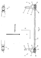
- FIG. 1 shows the basic structure of a cab storage for commercial vehicles.
- the cab not shown, is mounted on four cab bearings 1, 2, 3, 4.
- the two seen in the direction of travel front cab bearings 1, 2 each have a support arm 5.
- the support arm 5 has a support arm 6, which is connected via connecting means, not shown, with the cab. Seen in the direction of travel, the support arm 6 branches into two fork-shaped arranged pins 7, 8.
- the two pins 7, 8 are connected via a pivot axis 9 with each other.
- the structural design of the pivot axis 9 will be described in more detail below.
- vehicle outer pin 7 The each arranged on the vehicle outer side of the vehicle centerline pin 7 (hereinafter referred to as "vehicle outer pin 7") has a through hole 10 through which the pivot axis 9 can be inserted.
- a second hole 11 is provided, which is formed in the illustrated embodiment as a blind hole and in which the pivot axis 9 is inserted.
- the second hole 11 may also be formed as a through hole. In any case, however, the second hole 11 is not accessible to the fitter because of the stabilizer 13 attached to the vehicle-internal pin 8.
- a rolling bearing is arranged, via which the pivot axis 9 is rotatably mounted and low friction.
- the two vehicle-inner pin 8 of the left and right front cab bearings are coupled together via a stabilizer 13.
- a stabilizer 13 In such a construction is due to the connection of the stabilizer 13 only a one-sided Accessibility of the second hole 11 given for the installation of the pivot axis 9, because the pivot axis 9 can be inserted only from the vehicle outer side through the through hole 10 in the second hole 11.
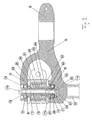
- Fig. 2 shows a first embodiment of the cab bearing according to the invention.
- the one roller bearing 14 is inserted into the through hole 10 of the vehicle outer pin 7, while the other roller bearing 15 is inserted into the second hole 11 of the vehicle outer pin 8.
- the pivot axis 9 is formed in two parts. It comprises a central screw 17 and a surrounding pivot sleeve 18.
- the inner rings of the bearings 14, 15 are based on the jacket of a pivot sleeve 18, while the outer rings of the roller bearings 14, 15 on the inner wall of the through hole 10 and the second hole 11 support.
- the pivot sleeve 18 has a collar 19 on the vehicle outside, which is supported on the inner ring of the arranged in the through hole 10 rolling bearing 14.
- the screw 17 is supported with its screw head 17a on the pivot sleeve 18.
- a sliding sleeve 20 is arranged in the second hole 11.
- the sliding sleeve 20 has a central bore 21 with an internal thread into which the external thread 17b of the screw 17 is screwed.
- the sliding sleeve 20 has a vehicle inside arranged collar 22, which is supported against the inner ring of the arranged in the second hole 11 rolling bearing 15.
- a clamping sleeve 23 is arranged, via which the inner rings of the rolling bearings 14, 15 are supported against each other.
- a metal disc 24 is disposed between the inner ring of the vehicle inner roller bearing 15 and the clamping sleeve 23, through which the inner ring of the rolling bearing 15 is fixed in the axial direction.
- the outer ring of the rolling bearing 15 is by the snap ring 27 in the axial direction established.
- the vehicle-inner roller bearing 15 is formed as a fixed bearing, while the vehicle outer roller bearing 14 is designed as a floating bearing.
- this could also be reversed without affecting the principle of the present invention.
- the inner rings of the roller bearings 14, 15 can be braced against one another essentially without play.
- the screw 17 is screwed with its external thread 17b in the internal thread of the central bore 21 of the sliding sleeve 20. So that the screwing succeeds and the sliding sleeve 20 does not rotate with the sliding sleeve 20 is formed with a shaft 25 which is guided by means of a circumferentially effective positive connection in a recess 26 of the pivot sleeve 18. In this way, the sliding sleeve 20 guided in the recess 26 of the pivot sleeve 18 are moved and at the same time it is secured against rotation when screwing the screw 17.
- the clamping sleeve 23 is formed as a metal inner sleeve of a rubber-metal sleeve 30.
- the rubber-metal sleeve 30 comprises, in addition to the existing metal, serving as a clamping sleeve 23 inner sleeve disposed on the outer surface of the clamping sleeve 23 rubber layer 31 which is vulcanized onto the clamping sleeve 23.
- the rubber layer 31 is surrounded by a further metal sleeve 35, wherein the rubber layer 31 and the metal sleeve 35 are connected to each other by vulcanization.
- the pivot axis 9 is connected to the (not shown) vehicle frame.
- the outer metal sleeve 35 of the rubber-metal sleeve 30 is pressed so that the rubber-metal sleeve 30 is rotationally held in the ring 34.
- the sliding sleeve 20 is first inserted into the second hole 11.
- the second hole 11 has a small receiving space 11a into which the collar 22 of the sliding sleeve 20 fits.
- the rolling bearing 15 is inserted into the second hole 11, fixed with a snap ring, and the disc 24 is inserted.
- the rubber-metal sleeve 30 is inserted from the open side of the forked support arm 5 between its pins 7, 8.
- the inner sleeve of the rubber-metal sleeve 30 is aligned with the inner rings of the bearings 14, 15 so that they can act as a clamping sleeve 18, that can be supported in the clamped state on the inner rings of the bearings 14, 15.
- the sliding sleeve 20 is held against rotation in the circumferential direction in the pivot sleeve 18.
- the collar 19 of the pivot sleeve 18 is supported directly on the inner ring of the vehicle outer bearing 14.
- the screw 17 is screwed with its external thread 17b in the internal thread of the sliding sleeve 20.
- the sliding sleeve 20 is arranged against rotation and slidable in the longitudinal direction in the recess 26 of the pivot sleeve 18, so that by screwing the screw 17, the sliding sleeve 20 is moved to the screw head 17a until the collar 22 of the sliding sleeve 20 to the inner ring of the bearing 15 applies.
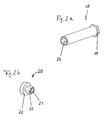
- Fig. 2a is the pivot sleeve 18 and in Fig. 2b the sliding sleeve 20 is shown in a perspective view to illustrate the principle of operation of the tension in the first embodiment of the invention.
- the collar 19 with which the pivot sleeve 18 is supported on the outside of the inner ring of the roller bearing 14, and the recess 26, which has a hexagon socket and in which the shaft 25 of the sliding sleeve 20 (see Fig. 2b ) is insertable.
- the sliding sleeve 20 is supported with its collar 22 on the inner ring of the vehicle inner side roller bearing 15.
- the sliding sleeve 20 also has a central bore 21 into which the screw 17 can be screwed.
- Fig. 3 shows an embodiment of the invention, compared with the in Fig. 2 modified embodiment shown is modified.
- the basic operating principle for the bracing of the rolling bearings 14, 15 against each other, as above Fig. 2 has been explained, also applies to the modified embodiment according to Fig. 3 ,
- the pivot axis 9 does not comprise a pivot sleeve surrounding a screw, but the pivot axis 9 is formed by a threaded bolt 40 which has a threaded sleeve-side threaded shoulder 41 and a threaded shoulder 42 on the vehicle outer side.
- the sliding sleeve 43 is formed here as a simple cylindrical ring having a central bore with internal thread and at least two holes 44 for receiving locking pins 45.
- the second hole 11 also has holes 46 in which the locking pins 45 stuck.
- the locking pins 45 inserted in the bores 46 engage in the bores 44 of the sliding sleeve 43 and prevent the sliding sleeve 43 from rotating in the circumferential direction when the sliding sleeve-side threaded shoulder 41 in FIG the internal thread of the central bore of the sliding sleeve 43 is screwed (anti-rotation).
- the sliding sleeve 43 has no collar, but acts with its rolling bearing-side end face directly on the inner ring of the rolling bearing 15th
- the vehicle outer side threaded shoulder 42 has a hexagon socket 47 through which the threaded bolt 40 can be screwed into the sliding sleeve 43.
- a nut 48 is screwed on the vehicle outer side threaded shoulder 42.
- the nut 48 acts via a clamping washer 49 on the inner ring of the rolling bearing 14 a.
- the advantage can be seen in the fact that the sliding sleeve can be made simpler than in the embodiment according to FIG Fig.
Landscapes
- Engineering & Computer Science (AREA)
- General Engineering & Computer Science (AREA)
- Mechanical Engineering (AREA)
- Chemical & Material Sciences (AREA)
- Combustion & Propulsion (AREA)
- Transportation (AREA)
- Rolling Contact Bearings (AREA)
- Pivots And Pivotal Connections (AREA)
Applications Claiming Priority (1)
| Application Number | Priority Date | Filing Date | Title |
|---|---|---|---|
| DE102007041647A DE102007041647A1 (de) | 2007-09-03 | 2007-09-03 | Lagerbefestigung |
Publications (2)
| Publication Number | Publication Date |
|---|---|
| EP2030875A2 true EP2030875A2 (fr) | 2009-03-04 |
| EP2030875A3 EP2030875A3 (fr) | 2009-07-08 |
Family
ID=40076627
Family Applications (1)
| Application Number | Title | Priority Date | Filing Date |
|---|---|---|---|
| EP08013728A Withdrawn EP2030875A3 (fr) | 2007-09-03 | 2008-07-31 | Fixation de palier |
Country Status (2)
| Country | Link |
|---|---|
| EP (1) | EP2030875A3 (fr) |
| DE (1) | DE102007041647A1 (fr) |
Cited By (2)
| Publication number | Priority date | Publication date | Assignee | Title |
|---|---|---|---|---|
| WO2013129993A1 (fr) * | 2012-02-28 | 2013-09-06 | Scania Cv Ab | Barre stabilisatrice |
| IT202200002366A1 (it) * | 2022-02-09 | 2023-08-09 | On Highway Brasil Ltda | Sistema di supporto migliorato per una barra stabilizzatrice di un sistema di sospensione |
Family Cites Families (6)
| Publication number | Priority date | Publication date | Assignee | Title |
|---|---|---|---|---|
| SE502965C2 (sv) * | 1992-12-28 | 1996-03-04 | Scania Cv Ab | Förfarande och anordning vid upphängning av en avfjädrad fordonshytt vid en fordonsram |
| SE502395C2 (sv) * | 1994-03-04 | 1995-10-16 | Saab Scania Ab | Anordning vid upphängning av en avfjädrad fordonshytt vid en fordonsram |
| DE10037890A1 (de) * | 2000-08-03 | 2002-02-21 | Thyssen Krupp Automotive Ag | Kippvorrichtung für ein Fahrerhaus |
| SE518723C2 (sv) * | 2001-12-27 | 2002-11-12 | Scania Cv Abp | Bussningsarrangemang för en krängningshämmare samt ett främre upphängnings-och avfjädringsarrangemang för en hytt |
| SE528796C2 (sv) * | 2005-04-12 | 2007-02-20 | Kongsberg Automotive Asa | Krängningshämmare innefattande en torsionsstång samt förfarande för demontering och montering av en torsionsstång |
| SE530551C2 (sv) * | 2006-11-02 | 2008-07-08 | Scania Cv Abp | Bussningsarrangemang för en krängningshämmare |
-
2007
- 2007-09-03 DE DE102007041647A patent/DE102007041647A1/de not_active Ceased
-
2008
- 2008-07-31 EP EP08013728A patent/EP2030875A3/fr not_active Withdrawn
Cited By (8)
| Publication number | Priority date | Publication date | Assignee | Title |
|---|---|---|---|---|
| WO2013129993A1 (fr) * | 2012-02-28 | 2013-09-06 | Scania Cv Ab | Barre stabilisatrice |
| CN104067022A (zh) * | 2012-02-28 | 2014-09-24 | 斯堪尼亚商用车有限公司 | 稳定杆 |
| JP2015509878A (ja) * | 2012-02-28 | 2015-04-02 | スカニア シーブイ アクチボラグ | スタビライザ・バー |
| RU2577814C1 (ru) * | 2012-02-28 | 2016-03-20 | Сканиа Св Аб | Стержень стабилизатора |
| EP2820320A4 (fr) * | 2012-02-28 | 2016-03-23 | Scania Cv Ab | Barre stabilisatrice |
| CN104067022B (zh) * | 2012-02-28 | 2016-09-07 | 斯堪尼亚商用车有限公司 | 稳定杆 |
| IT202200002366A1 (it) * | 2022-02-09 | 2023-08-09 | On Highway Brasil Ltda | Sistema di supporto migliorato per una barra stabilizzatrice di un sistema di sospensione |
| WO2023152646A1 (fr) * | 2022-02-09 | 2023-08-17 | On-Highway Brasil Ltda. | Système de support amélioré pour barre stabilisatrice pour système de suspension |
Also Published As
| Publication number | Publication date |
|---|---|
| EP2030875A3 (fr) | 2009-07-08 |
| DE102007041647A1 (de) | 2009-03-19 |
Similar Documents
| Publication | Publication Date | Title |
|---|---|---|
| DE102008049489B4 (de) | Lenkungszahnstangen-Verschleißausgleichsvorrichtung | |
| DE102019102348B4 (de) | Servolenkungsanordnung und lagerjustierungsanordnung | |
| DE102006004678A1 (de) | Montageeinheit für die Befestigungsöse eines Gurtschlosses | |
| DE102019209930A1 (de) | Aktuator einer steer-by-wire-Lenkung mit einem Spindelantrieb sowie steer-by-wire-Lenkung | |
| EP3819136B1 (fr) | Unité de roulement de roue pour un véhicule à moteur et procédé de fabrication d'une unité de roulement de roue | |
| DE102022105548A1 (de) | Luftleitvorrichtung einer Kraftfahrzeugkarosserie eines Kraftfahrzeugs | |
| DE10316190A1 (de) | Klemmvorrichtung zur Lagefixierung einer Lenksäule | |
| EP2030875A2 (fr) | Fixation de palier | |
| DE102012011048B4 (de) | Scharniervorrichtung und eine Türanlage mit der Scharniervorrichtung | |
| DE102005017746B4 (de) | Einbauanordnung für Antriebswellen in Kreuzgelenkgabeln | |
| DE19927754B4 (de) | Anhängerkupplung | |
| DE4022145A1 (de) | Verdrehbare, in bestimmten drehwinkeln arretierbare kugelpfanne | |
| DE4001145C2 (fr) | ||
| DE3525815C1 (de) | Stützlager | |
| DE102007021059A1 (de) | Flexibles Gelenk | |
| DE102017214320B4 (de) | Aktuator einer Hinterachslenkung für ein Kraftfahrzeug | |
| DE102022203668B4 (de) | Schwenklager, Gelenkzapfen und Kraftfahrzeug | |
| DE4123624C2 (de) | Verbindung zwischen Bolzen und Tragteil sowie Pendellagerung | |
| DE102004014301A1 (de) | Radschraube für ein Kraftfahrzeugrad | |
| DE19939829A1 (de) | Türscharnier mit Schwenkhemmung | |
| DE102018213776A1 (de) | Aktuator einer Hinterachslenkung für ein Kraftfahrzeug | |
| WO2003097429A1 (fr) | Ensemble d'articulation double | |
| DE102022121725A1 (de) | Lagerungsanordnung eines Radlenkers an einem Träger eines Fahrzeugs sowie Fahrzeug | |
| DE4243149A1 (de) | Scharnier | |
| DE102016102149B4 (de) | Um einen Lagerbolzen pendelndes Pendellager |
Legal Events
| Date | Code | Title | Description |
|---|---|---|---|
| PUAI | Public reference made under article 153(3) epc to a published international application that has entered the european phase |
Free format text: ORIGINAL CODE: 0009012 |
|
| AK | Designated contracting states |
Kind code of ref document: A2 Designated state(s): AT BE BG CH CY CZ DE DK EE ES FI FR GB GR HR HU IE IS IT LI LT LU LV MC MT NL NO PL PT RO SE SI SK TR |
|
| AX | Request for extension of the european patent |
Extension state: AL BA MK RS |
|
| PUAL | Search report despatched |
Free format text: ORIGINAL CODE: 0009013 |
|
| AK | Designated contracting states |
Kind code of ref document: A3 Designated state(s): AT BE BG CH CY CZ DE DK EE ES FI FR GB GR HR HU IE IS IT LI LT LU LV MC MT NL NO PL PT RO SE SI SK TR |
|
| AX | Request for extension of the european patent |
Extension state: AL BA MK RS |
|
| 17P | Request for examination filed |
Effective date: 20100108 |
|
| 17Q | First examination report despatched |
Effective date: 20100202 |
|
| AKX | Designation fees paid |
Designated state(s): AT BE BG CH CY CZ DE DK EE ES FI FR GB GR HR HU IE IS IT LI LT LU LV MC MT NL NO PL PT RO SE SI SK TR |
|
| STAA | Information on the status of an ep patent application or granted ep patent |
Free format text: STATUS: THE APPLICATION HAS BEEN WITHDRAWN |
|
| 18W | Application withdrawn |
Effective date: 20100302 |