EP2030882B1 - Carénage pour motocyclette et motocyclette équipée d'un tel carénage - Google Patents
Carénage pour motocyclette et motocyclette équipée d'un tel carénage Download PDFInfo
- Publication number
- EP2030882B1 EP2030882B1 EP07017225A EP07017225A EP2030882B1 EP 2030882 B1 EP2030882 B1 EP 2030882B1 EP 07017225 A EP07017225 A EP 07017225A EP 07017225 A EP07017225 A EP 07017225A EP 2030882 B1 EP2030882 B1 EP 2030882B1
- Authority
- EP
- European Patent Office
- Prior art keywords
- support element
- assembly
- motorcycle
- extending
- receive
- Prior art date
- Legal status (The legal status is an assumption and is not a legal conclusion. Google has not performed a legal analysis and makes no representation as to the accuracy of the status listed.)
- Active
Links
Images


Classifications
-
- B—PERFORMING OPERATIONS; TRANSPORTING
- B62—LAND VEHICLES FOR TRAVELLING OTHERWISE THAN ON RAILS
- B62J—CYCLE SADDLES OR SEATS; AUXILIARY DEVICES OR ACCESSORIES SPECIALLY ADAPTED TO CYCLES AND NOT OTHERWISE PROVIDED FOR, e.g. ARTICLE CARRIERS OR CYCLE PROTECTORS
- B62J17/00—Weather guards for riders; Fairings or stream-lining parts not otherwise provided for
- B62J17/02—Weather guards for riders; Fairings or stream-lining parts not otherwise provided for shielding only the rider's front
-
- B—PERFORMING OPERATIONS; TRANSPORTING
- B62—LAND VEHICLES FOR TRAVELLING OTHERWISE THAN ON RAILS
- B62K—CYCLES; CYCLE FRAMES; CYCLE STEERING DEVICES; RIDER-OPERATED TERMINAL CONTROLS SPECIALLY ADAPTED FOR CYCLES; CYCLE AXLE SUSPENSIONS; CYCLE SIDECARS, FORECARS, OR THE LIKE
- B62K19/00—Cycle frames
- B62K19/30—Frame parts shaped to receive other cycle parts or accessories
Definitions
- the present invention relates to the field of motor cycles.
- the present invention relates to a front cowling assembly for a motor cycle and a respective motor cycle equipped with such a cowling assembly.
- the present invention relates to the way such a cowling assembly is mounted to and removed from a motor cycle.
- those accessories and/or equipments usually belonging to the front cowling element of a motor cycle may be cited; these accessories and/or component parts in turn may comprise a front cowling cover, rear mirrors, front headlights and/or direction indicators, the speedometer, the fuel level indicator, the oil pressure indicator, the cooling fluid level indicator and similar equipments.
- these accessories and/or component parts in turn may comprise a front cowling cover, rear mirrors, front headlights and/or direction indicators, the speedometer, the fuel level indicator, the oil pressure indicator, the cooling fluid level indicator and similar equipments.
- Still another disadvantage affecting the prior art solutions relates to the fact that the operator, for the purpose of removing component parts or accessories or even equipments from the cowling assembly is requested to stay beside the motor cycle; the same then furthermore applies when the component parts, accessories, or equipments have to be mounted again to the cowling assembly.
- cowling assemblies for motorcycles can be found in each of documents DE 103 42 106 A1 and DE 10 2004 057 132 A1
- an object of the present invention to provide a solution allowing to overcome the problems as stated above.
- the present invention is based on the consideration that the problems affecting the prior art solutions, in particular, the prior art cowling assemblies may be overcome if the cowling assembly, as a whole, can be mounted to and removed from the motor cycle.
- the overall cowling assembly may be assembled and/or finished first, and then subsequently mounted as a whole to the motor cycle.
- the possibility is offered to the operator to mount each of the accessories belonging to the cowling assembly singularly and in convenient conditions to the cowling assembly, so that this cowling assembly, along with the accessories mounted thereto, can be subsequently mounted to the motor cycle as a single piece or part.
- said cowling assembly may be first removed from the motor cycle as a whole, thus allowing the operator to work on one or more of the accessories or equipments of the motor cycle in easy and convenient conditions.
- Still a further consideration on which the present invention is made relates to the fact that the problems affecting the prior art solutions, in particular, the prior art cowling assemblies, can be overcome or at least, drastically reduced or minimized by providing a cowling assembly comprising a support element with fixing means adapted to allow said support element and the overall cowling assembly to be quickly mounted to and removed from the motor cycle.
- Another consideration on which the present invention is made relates to the fact that the operation for mounting and/or removing the cowling assembly may be further accelerated or speeded-up if the fixing means of the support element are located in a position easily accessible by an operator.
- the present invention is understood to be of particular advantage when applied to two-wheeled motor cycles, such as, for instance, motor bikes. For this reason, examples will be given in the following, in which corresponding embodiments of the front cowling assembly according to the present invention are applied to motor bikes. However, it has to be appreciated that the applications of the front cowling assembly according to the present invention are not limited to the case of motor bikes. On the contrary, the front cowling assembly according to the present invention may also be applied to other motor cycles and/or motor vehicles, in particular, to three or even four-wheeled motor cycles such as for instance, choppers, quads or the like.
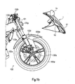
- FIG. 1a the front portion of a motor cycle 100 is depicted.
- Fig. 1a essentially the front portion of a motor cycle has been depicted whilst some portions or component parts or even accessories or equipments common to usual motor cycles have been omitted in Fig. 1 for the sake of clarity, the essential features of common motor cycles may be recognized when looking at Fig. 1a .
- These features relate in particular, to a front wheel 100w, with said front wheel 100w comprising a brake disk 100b and being supported by a front fork 100f; said front fork 100f supports moreover a front fender 100m provided to avoid the driver and/or passenger or even the motor cycle 100 from being splashed with mud or water lying on the bottom or the like.
- Side covering elements 100c are mounted to the motor cycle 100 on opposite sides thereof; components of the motor cycle 100 such as, for instance, the engine, the crankcase, the cylinder or the like have therefore to be understood as being located in the area defined by said side covering elements 100c, in combination, and therefore, as being located behind the right-side cover element 100c depicted in Fig. 1 .
- the motor cycle 100 further comprises a fuel tank 100t (partially covered by the side covering element 100c), along with a handlebar 100h provided with brake handles and corresponding cables extending therefrom.
- a front cowling assembly 1 is mounted to the motor cycle 100, with said front cowling assembly 1, supporting and/or comprising as depicted in Fig.
- the motor cycle 100 comprises, in the area defined by said side covering elements 100c, a radiator 100r and an exhaust gas purifying pipe 100e.
- the front fork 100f supporting the front wheel 100w and the front fender 100m extends from a steering tube 101 which is in turn fixed and/or connected to the main frame (not depicted in the drawings) of the motor cycle 100. It appears moreover from Fig.
- a fixing element 101p extends from the steering tube 101; as it will be better appreciated by means of the following disclosure, said fixing element 101p belongs to fixing means adapted to allow the front cowling assembly 1 to be mounted to the motor cycle 100 as depicted in Fig. 1a .
- the same considerations also apply to the front cowling assembly 1 depicted in Figs. 1a and 1b ; in fact, even if essentially only the rear mirrors 1h, the headlights 1f and the front direction indicators 1b have been explicitly identified in Fig. 1b as belonging or being supported by the front cowling assembly 1, it has to be appreciated that said front cowling assembly 1 is adapted to support other equipments in addition to those clearly depicted and identified in Fig. 1b .
- This additional equipments may comprise, for instance, a speedometer, a fuel level indicator, an oil pressure indicator, a cooling fluid level indicator and/or even further equipments usually needed by the driver to check and/or manage the functioning of the motor cycle 100.
- the front cowling assembly 1 Whilst further details and/or features of the front cowling assembly 1 according to the present invention will be comprehensively described in the following, it can be appreciated at present, when looking at Figs. 1a and 1b , in combination, that the basic idea of the present invention relates to the fact that the front cowling assembly 1 depicted therein may be mounted to and removed from the motor cycle 100 as a whole. That means, that for instance removing the front cowling assembly 1 from the motor cycle 100, results in all those accessories or equipments supported by said front cowling assembly 1 being also removed from the motor cycle 100 with a unique operation. The same applies when the front cowling assembly 1 has to be mounted to the motor cycle 100; mounting said front cowling assembly 1 to the motor cycle as depicted in Fig.
- said accessories and/or equipments supported by or belonging to the front cowling assembly 1 may comprise the rear mirrors 1h, the headlights 1f and the front direction indicators 1d identified in Fig. 1b , along with other accessories and/or equipments, such as a speedometer and/or similar control equipments.
- the operator when for instance, the need arises to repair or even substitute one of said equipment, let's say the fuel level indicator, the operator is not requested to stay beside the motor cycle and to work in difficult conditions; on the contrary, the possibility is given to the operator, to entirely remove the front cowling assembly 1 from the motor cycle, to put it for instance on a working table so as to be allowed to repair or substitute said fuel level indicator in convenient conditions, for instance, even sitting. Accordingly, the operator may turn or move the front cowling assembly 1 so as to dispose it in the most convenient position offering easy access to said fuel level indicator.
- the operations may therefore be accelerated and/or speeded up, with evident corresponding advantages in terms of reduced and/or contained costs.
- FIG. 2a and 2b some additional features and/or details of the front cowling assembly according to the present invention will be disclosed; in Figs. 2a and 2b , those features which have already been described with reference to Figs. 1a and 1b are identified by the same reference numerals.
- the front cowling assembly 1 comprises a support element 1s and a front cowling cover 1c; moreover, as apparent from Fig. 2a , said front cowling cover is adapted to be supported by said support element 1s.
- fixing means may be provided, such as, for instance, clips, screws, bolts or the like.
- the rear mirrors 1h, the headlights 1f and the front direction indicators 1d are mounted directly to the front cowling cover 1c.
- said accessories are mounted to the support element 1s.
- the front cowling cover 1c will comprise corresponding apertures adapted to receive said accessories.
- the support element 1s (the shape and layout of which will be more comprehensively described in the following) comprises a front end portion or surface 1fp adapted to match with the front cowling cover 1c, along with a rear end portion 1sr.
- the support element 1s comprises a top or upper surface 1u, from which two opposite side walls 1ll and 1lr (see also, Fig. 4b ) extends downward so as to define a recess or cavity 1ca below said upper or top surface 1u.
- fixing means 1a are provided, with said fixing means 1a allowing the support element 1s to be connected or fixed through its rear end portion 1sr to the main frame of the motor cycle, in particular, to the plate 101p extending from the steering tube 1001.
- the front cowling assembly 1 may be mounted and removed as a whole, to and from the motor cycle 100, respectively by simply detaching from and fixing to, respectively the support element 1s of said front cowling assembly 1; these may, in particular, be obtained by acting on the fixing means 1a which co-operate with the protruding plate 101p extending from the steering tube 101.
- a simple, unique operation is therefore requested for removing from and/or mounting to the motor cycle 100, all the equipments supported by or belonging to the front cowling assembly 1, simultaneously.
- the position at which the fixing means 1a are located allows easy access to said fixing means 1a, so that mounting and/removing the whole front cowling assembly 1 results in being strongly simplified, thus resulting in the corresponding operations being accelerated and the resulting costs being reduced.
- the support element 1s comprises, in its rear end portion 1sr, a slot 1sl adapted to receive the protruding plate 101p.
- the support element 1s During mounting of the front cowling assembly 1 to the motor cycle, it is therefore requested first to act on the support element 1s so as to allow the protruding plate 101p to enter into the slot 100sl so as to be received inside said slot 100sl.
- said fixing means 1a are introduced into corresponding through holes provided in the opposite walls 1w defining the slot 1sl, with said fixing means being equally received into corresponding through holes provided in the protruding plate 101p.
- said fixing means 1a may comprise screws, bolts or the like. Screwing the fixing means 1a results in the walls 1w to be forced to come into abutment with the protruding plate 101p so that the support element 1s is stably and reliably fixed to the protruding plate 101p due to the resulting friction.
- both the through holes 1st provided in the rear end portion 1sr of the support element 1s and the corresponding through holes 101t provided in the protruding plate 101p of the steering tube 101 have an elongated curved shape. Even if said through holes 1st and 101t are adapted, like the circular through holes of the embodiment depicted in Fig. 3a to receive the screwing means 1a, said through holes 1st and 101t of the embodiment depicted in Fig. 3b allows to regulate the position of the support element 1s with respect to the protruding plate 101p and accordingly, with respect to the steering tube 101 and the overall main frame of the motor cycle.
- the most convenient inclination of the support element 1s and accordingly, of the whole front cowling assembly 1 with respect to the motor cycle may be selected by introducing the screwing means 1a into said through holes 1st and 101t, orienting the support element 1s until the desired position is reached and screwing the screwing means 1a so as to firmly fix the support element 1s to the protruding plate 101p in the desired position.
- the support element 1s comprises, in its front end portion 1fp fixing means 1f adapted to allow the left and right rear mirrors to be fixed to said support element 1s.
- the front cowling cover 1c will therefore comprise two corresponding apertures adapted to receive the fixing means 1ff and the corresponding bottom end portion of said left and right rear mirrors.
- the fixing means 1ff may be provided on said front cowling cover 1c so as to allow the left and right rear mirrors to be fixed directly to said front cowling cover 1c.
- Further through holes 1fo are provided in the front end portion 1fp of the support element 1s for the purpose of allowing the front cowling cover 1c to be fixed to said support element 1s.
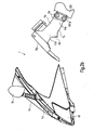
- the shape and configuration of the support element 1s of the front cowling assembly according to the present invention may be well appreciated when looking at Fig. 4b ; it appears in fact, clearly, from Fig. 4b that said support element comprises a top or upper wall 1u from which side walls 1ll and 1lr extends on opposite sides thereof. Said side walls 1ll and 1lr come close to each other in proximity of the rear end portion 1sr of the support element 1s. It is in said rear end portion 1sr that there is provided the slot 1sl adapted to receive the protruding plate 101p extending from the steering tube 101 of the motor cycle (see also Fig. 3a ). According to the particular embodiment depicted in Fig.
- the slot 1sl is open at the bottom and closed at the top; this solution allows during mounting to the motorcycle of the cowling assembly 1 according to the present invention to be set on the protruding plate 101p so as to rest on said protruding plate 101p. This allows the assembly and/or mounting operation to be further simplified since the operator is allowed to use both hands for acting on the screwing means 1a without any need to use one hand for holding the front cowling assembly 1.
- the side walls 1ll and 1lr extend so as to come away from each other in proximity of the front end portion 1fb by means of which said side walls 1ll and 1lr are connected.
- a plurality of receiving seats or apertures 1si are provided; said receiving seats, recesses, cavities or even through apertures 1si are provided for allowing a corresponding plurality of equipments to be mounted to the support element 1s.
- said plurality of equipments may comprise a fuel level indicator, an oil pressure indicator, control lights or the like.
- a further main receiving seat, recess or aperture 1sk is formed in the top wall 1u of the support element 1s.
- These receiving seat or aperture is adapted to allow the speedometer of the motor cycle to be mounted to said support element 1s.
- the electrical cables and harness provided to supply electrical current to the plurality of equipments mounted to the upper wall 1u of the support element 1s will therefore extend from said equipments into the recess 1ca (see also, Fig. 2b ) defined by the upper wall 1u, in combination with the side walls 1ll, 1lr and the front end portion 1fp.
- a convenient receiving place for arranging said cables is therefore, provided.
- the electrical cables may be connected to one or more sockets or plugs also received in the cavity or recess 1ca.
- Corresponding plugs or sockets may therefore also be provided on the motor cycle, so that said cable may be disconnected by simply acting on said plugs or sockets. If only one socket or plug is provided to which all the electrical cables are connected and a unique corresponding socket or plug is provided on the side of the motor cycle, all said electrical cables may be connected or disconnected from a source of electrical power of the motor cycle (for instance, the battery) by simply connecting and/or disconnecting the unique socket and/or plug received for instance in the recess 1ca to and from a corresponding unique plug and/or socket provided on the motor cycle.
- a source of electrical power of the motor cycle for instance, the battery
- the present invention allows to overcome or at least to strongly reduce or minimize the drawbacks affecting the prior art front cowling assemblies.
- the front cowling assembly according to the present invention allows easy and quick mounting to and removing from the motor cycle, with corresponding evident advantages in terms of easy maintenance and corresponding reduced costs.
- a convenient orientation and/or inclination of the whole front cowling assembly with respect to the motor cycle.
- a convenient storing place is provided for arranging the cables provided for supplying electrical current to the equipments supported by or belonging to the front cowling assembly, a quick and easy way being also offered for the purpose of connecting and/or disconnecting said electrical cables to the source of electrical power of the motor cycle, for instance, the battery.
- the rear end portion of the support element of the front cowling assembly may be provided with a slot extending in a direction substantially horizontal, with said slot therefore being adapted to receive a corresponding protruding plate extending from the steering tube of the motor cycle in a direction substantially horizontal.
Landscapes
- Engineering & Computer Science (AREA)
- Mechanical Engineering (AREA)
- Motorcycle And Bicycle Frame (AREA)
- Automatic Cycles, And Cycles In General (AREA)
- Professional, Industrial, Or Sporting Protective Garments (AREA)
- Passenger Equipment (AREA)
Claims (22)
- Assemblage de carénage frontal (1) pour une motocyclette (100) comprenant un premier châssis, ledit assemblage (1) comprenant un élément de support (1s) supportant au moins un capot de carénage frontal (1c) et apte à supporter au moins un compteur de vitesse, ledit élément de support (1s) étant apte à être fixé audit châssis et détaché dudit châssis de ladite motocyclette (100) de sorte que la fixation dudit élément de support (1s) audit châssis et le détachement dudit élément de support (1s) dudit châssis ont pour conséquence que ledit assemblage (1) est respectivement fixé audit châssis et détaché dudit châssis ;
ledit élément de support (1s) comprenant une partie frontale (1fp) faisant face à l'opposé d'un pilote ou d'un passager de ladite motocyclette (100) et une partie arrière (1sr) opposée à ladite partie frontale (1fp) et faisant face à un pilote ou un passager de ladite motocyclette (100) une fois que ledit élément de support (1s) a été fixé audit châssis, ladite partie arrière (1sr) dudit élément de support (1s) étant apte à être fixée audit châssis et déposée dudit châssis de ladite motocyclette (100) ;
caractérisé en ce que
ledit élément de support (1s) comprend une paroi supérieure (1u) apte à supporter ledit au moins un compteur de vitesse et s'étendant entre ladite partie frontale (1fp) et ladite partie arrière (1sr), avec deux parois latérales opposées (1ll, 1lr) s'étendant vers le bas à partir de ladite paroi supérieure (1u) et se rapprochant l'une de l'autre à proximité de ladite partie arrière (1sr), en ce que dans ladite partie arrière (1sr) il est prévu une fente (1sl), et en ce que ladite fente (1sl) est apte à recevoir au moins une partie d'une plaque (101p) s'étendant de la colonne de direction (101) dudit châssis principal de ladite motocyclette. - Assemblage selon la revendication 1,
caractérisé en ce que :lesdites deux parois opposées (1ll, 1lr) comprennent des trous traversants (1st) aptes à recevoir un moyen de fixation (1a) pour fixer ledit élément de support (1s) à ladite plaque (101p) s'étendant de ladite colonne de direction (101). - Assemblage selon la revendication 2,
caractérisé en ce que :lesdits trous traversants (1st) sont de type apte à recevoir un moyen de vissage (1a). - Assemblage selon la revendication 3,
caractérisé en ce que :ledit moyen de vissage (1a) est apte à être reçu dans des trous correspondants (101t) de ladite plaque (101p) s'étendant de ladite colonne de direction (101). - Assemblage selon l'une quelconque des revendications 1 à 4,
caractérisé en ce que :ladite fente (1sl) est définie par lesdites deux parois latérales opposées (1ll, 1lr) et s'étend dans une direction sensiblement verticale de manière à être apte à recevoir au moins une partie de ladite plaque protubérante (101p), avec ladite plaque protubérante (101p) s'étendant sensiblement parallèlement à ladite colonne de direction (101). - Assemblage selon l'une quelconque des revendications 1 à 4,
caractérisé en ce que :ladite fente (1sl) s'étend dans une direction sensiblement horizontale de manière à être apte à recevoir au moins une partie de ladite plaque protubérante (101p), avec ladite plaque protubérante (101p) s'étendant sensiblement perpendiculairement à ladite colonne de direction (101). - Assemblage selon l'une quelconque des revendications 1 à 6,
caractérisé en ce que :ledit élément de support (1s) comprend en outre un évidement de réception (1ca) apte à au moins partiellement recevoir ou héberger le faisceau électrique ou les câbles électriques aptes à connecter électriquement ledit au moins un compteur de vitesse à une source d'alimentation électrique de ladite motocyclette (100). - Assemblage selon la revendication 7,
caractérisé en ce que :ledit évidement (1ca) est défini par lesdites deux parois latérales opposées (1ll, 1lr) s'étendant vers le bas à partir de ladite paroi supérieure (1u) dudit élément de support (1s). - Assemblage selon la revendication 8,
caractérisé en ce que :ledit évidement (1ca) est situé au-dessous de ladite paroi supérieure (1u) et entre ladite partie frontale (1fp) et ladite partie arrière (1sr) dudit élément de support (1s) comprenant ladite fente (1sl). - Assemblage selon l'une quelconque des revendications 1 à 9,
caractérisé en ce que :ledit capot de carénage (1c) est monté sur ladite partie frontale (1fp) dudit élément de support (1s). - Assemblage selon l'une quelconque des revendications 1 à 10,
caractérisé en ce que :ledit assemblage comprend en outre au moins un rétroviseur (1h), et en ce que ledit au moins un rétroviseur (1h) est monté sur ledit capot de carénage (1c). - Assemblage selon l'une quelconque des revendications 1 à 11,
caractérisé en ce que :ledit assemblage comprend en outre au moins un phare (1f), et en ce que ledit au moins un phare (1f) est monté sur ledit capot de carénage (1c). - Elément de support (1s) pour une motocyclette (100) comprenant un châssis principal, ledit élément de support (1s) étant apte à supporter au moins un capot de carénage frontal (1c) et un compteur de vitesse de ladite motocyclette, ledit élément de support (1s) étant apte à être fixé audit châssis et détaché dudit châssis de ladite motocyclette (100) de sorte que la fixation dudit élément de support (1s) audit châssis et le détachement dudit élément de support (1s) dudit châssis ont pour conséquence que ledit au moins un capot de carénage (1c) et le compteur de vitesse sont respectivement fixés audit châssis et détachés dudit châssis, ensemble avec ledit élément de support (1s) sous la forme d'un assemblage ;
ledit élément de support (1s) comprenant une partie frontale (1fp) faisant face à l'opposé d'un pilote ou d'un passager de ladite motocyclette (100) et une partie arrière (1sr) opposée à ladite partie frontale (1fp) et faisant face à un pilote ou un passager de ladite motocyclette (100) une fois que ledit élément de support (1s) a été fixé audit châssis, ladite partie arrière (1sr) dudit élément de support (1s) étant apte à être fixée audit châssis et déposée dudit châssis de ladite motocyclette ;
caractérisé en ce que
ledit élément de support comprend une paroi supérieure (1u) apte à supporter ledit au moins un compteur de vitesse et s'étendant entre ladite partie frontale (1fp) et ladite partie arrière (1sr), avec deux parois latérales opposées (1ll, 1lr) s'étendant vers le bas à partir de ladite paroi supérieure (1u) et se rapprochant l'une de l'autre à proximité de ladite partie arrière (1sr), en ce que dans ladite partie arrière (1sr) il est prévu une fente (1sl), et en ce que
ladite fente (1sl) est apte à recevoir au moins une partie d'une plaque (101p) s'étendant de la colonne de direction (101) dudit châssis principal de ladite motocyclette. - Elément de support selon la revendication 13,
caractérisé en ce que :lesdites deux parois opposées (1ll, 1lr) comprennent des trous traversants (1st) aptes à recevoir un moyen de fixation (1a) pour fixer ledit élément de support (1s) à ladite plaque (101p) s'étendant de ladite colonne de direction (101). - Elément de support selon la revendication 14,
caractérisé en ce que :lesdits trous traversants (1st) sont de type apte à recevoir un moyen de vissage (1a). - Elément de support selon la revendication 15,
caractérisé en ce que :ledit moyen de vissage (1a) est apte à être reçu dans des trous correspondants (101t) de ladite plaque (101p) s'étendant de ladite colonne de direction (101). - Elément de support selon l'une quelconque des revendications 13 à 16,
caractérisé en ce que :ladite fente (1sl) est définie par lesdites deux parois latérales opposées (1ll, 1lr) et s'étend dans une direction sensiblement verticale de manière à être apte à recevoir au moins une partie de ladite plaque protubérante (101p), avec ladite plaque protubérante (101p) s'étendant sensiblement parallèlement à ladite colonne de direction (101). - Elément de support selon l'une quelconque des revendications 1 à 16,
caractérisé en ce que :ladite fente (1sl) s'étend dans une direction sensiblement horizontale de manière à être apte à recevoir au moins une partie de ladite plaque protubérante (101p), avec ladite plaque protubérante (101p) s'étendant sensiblement perpendiculairement à ladite colonne de direction (101). - Elément de support selon l'une quelconque des revendications 13 à 18,
caractérisé en ce que :ledit élément de support (1s) comprend en outre un évidement de réception (1ca) apte à au moins partiellement recevoir ou héberger le faisceau électrique ou le câble électrique apte à connecter électriquement ledit au moins un compteur de vitesse à une source d'alimentation électrique de ladite motocyclette (100). - Elément de support selon la revendication 19,
caractérisé en ce que :ledit évidement (1ca) est défini par lesdites deux parois latérales opposées (1ll, 1lr) s'étendant vers le bas à partir de ladite paroi supérieure (1u) dudit élément de support (1s). - Elément de support selon la revendication 20,
caractérisé en ce que :ledit évidement (1ca) est situé au-dessous de ladite paroi supérieure (1u) et entre ladite partie frontale (1fp) et ladite partie arrière (1sr) dudit élément de support (1s) comprenant ladite fente (1sl). - Elément de support selon l'une quelconque des revendications 13 à 21,
caractérisé en ce que :c'est ladite partie frontale (1fp) dudit élément de support (1s) qui est apte à supporter ledit capot de carénage (1c).
Priority Applications (3)
| Application Number | Priority Date | Filing Date | Title |
|---|---|---|---|
| DE602007004214T DE602007004214D1 (de) | 2007-09-03 | 2007-09-03 | Verkleidungsanordnung für ein Motorrad und mit einer solchen Verkleidungsanordnung ausgestattetes Motorrad |
| EP07017225A EP2030882B1 (fr) | 2007-09-03 | 2007-09-03 | Carénage pour motocyclette et motocyclette équipée d'un tel carénage |
| AT07017225T ATE454309T1 (de) | 2007-09-03 | 2007-09-03 | Verkleidungsanordnung für ein motorrad und mit einer solchen verkleidungsanordnung ausgestattetes motorrad |
Applications Claiming Priority (1)
| Application Number | Priority Date | Filing Date | Title |
|---|---|---|---|
| EP07017225A EP2030882B1 (fr) | 2007-09-03 | 2007-09-03 | Carénage pour motocyclette et motocyclette équipée d'un tel carénage |
Publications (2)
| Publication Number | Publication Date |
|---|---|
| EP2030882A1 EP2030882A1 (fr) | 2009-03-04 |
| EP2030882B1 true EP2030882B1 (fr) | 2010-01-06 |
Family
ID=38988302
Family Applications (1)
| Application Number | Title | Priority Date | Filing Date |
|---|---|---|---|
| EP07017225A Active EP2030882B1 (fr) | 2007-09-03 | 2007-09-03 | Carénage pour motocyclette et motocyclette équipée d'un tel carénage |
Country Status (3)
| Country | Link |
|---|---|
| EP (1) | EP2030882B1 (fr) |
| AT (1) | ATE454309T1 (fr) |
| DE (1) | DE602007004214D1 (fr) |
Families Citing this family (2)
| Publication number | Priority date | Publication date | Assignee | Title |
|---|---|---|---|---|
| CN106314619B (zh) * | 2015-06-24 | 2020-03-31 | 光阳工业股份有限公司 | 摩托车的头罩装置 |
| CN109131661B (zh) * | 2018-07-28 | 2023-08-29 | 重庆隆鑫机车有限公司 | 摩托车仪表安装结构及其摩托车 |
Family Cites Families (2)
| Publication number | Priority date | Publication date | Assignee | Title |
|---|---|---|---|---|
| JP4168713B2 (ja) | 2002-09-13 | 2008-10-22 | スズキ株式会社 | 自動二輪車の車体前部構造 |
| DE102004057132A1 (de) | 2004-09-08 | 2006-07-20 | Bayerische Motoren Werke Ag | Halteeinrichtung für Verkleidungskomponenten eines Motorrads |
-
2007
- 2007-09-03 DE DE602007004214T patent/DE602007004214D1/de active Active
- 2007-09-03 EP EP07017225A patent/EP2030882B1/fr active Active
- 2007-09-03 AT AT07017225T patent/ATE454309T1/de not_active IP Right Cessation
Also Published As
| Publication number | Publication date |
|---|---|
| ATE454309T1 (de) | 2010-01-15 |
| EP2030882A1 (fr) | 2009-03-04 |
| DE602007004214D1 (de) | 2010-02-25 |
Similar Documents
| Publication | Publication Date | Title |
|---|---|---|
| EP2165921B1 (fr) | Ensemble de réservoir de carburant pour motocyclette et motocyclette équipée d'un tel ensemble de réservoir de carburant | |
| JP5879346B2 (ja) | 鞍乗型車両 | |
| CN102869921B (zh) | 用于车辆应用的结构前灯组件 | |
| JP6026879B2 (ja) | 自動二輪車のヘッドランプ装置 | |
| US20040188156A1 (en) | Front end components for a saddle-type vehicle | |
| US10391925B2 (en) | Vehicle headlight with a plurality of inner non spherical lenses transmitting light from a high beam and a low beam light source | |
| EP2213536A1 (fr) | Motocyclette avec un arrangement particulier de batterie et d'unité ABS | |
| US20110273896A1 (en) | Headlamp device for two-wheeled motor vehicle | |
| EP2030882B1 (fr) | Carénage pour motocyclette et motocyclette équipée d'un tel carénage | |
| EP2077221B1 (fr) | Véhicule de type à enfourcher | |
| JP2007069678A (ja) | リヤフェンダー及び鞍乗型車両 | |
| EP2033885B1 (fr) | Ensemble de protection latérale pour motocyclette et motocyclette équipée d'un tel ensemble de protection latérale | |
| JP5427672B2 (ja) | 二輪車のライセンスライトの配線構造 | |
| EP4428019A1 (fr) | Structure de montage de caméra de véhicule | |
| CN115871792A (zh) | 全地形车 | |
| CN100418838C (zh) | 踏板摩托车 | |
| KR100783513B1 (ko) | 차량용 프론트 엔드 모듈의 마운팅 구조 | |
| JP2004243992A (ja) | 鞍乗り型車両のラジエータグリル取付構造 | |
| JP2018509341A (ja) | 自動二輪車用のヘッドライト取り付け構造 | |
| JP3583710B2 (ja) | 自動二輪車のヘッドランプ取付構造 | |
| JP2007069677A (ja) | 鞍乗型車両の後部構造、及び鞍乗型車両 | |
| CN210235173U (zh) | 车筐装置以及车辆 | |
| WO2022113106A1 (fr) | Composants électriques pour véhicule de type à selle | |
| JP2022144720A (ja) | 灯火器ユニット | |
| CN223924571U (zh) | 前照灯总成及车辆 |
Legal Events
| Date | Code | Title | Description |
|---|---|---|---|
| PUAI | Public reference made under article 153(3) epc to a published international application that has entered the european phase |
Free format text: ORIGINAL CODE: 0009012 |
|
| 17P | Request for examination filed |
Effective date: 20080612 |
|
| AK | Designated contracting states |
Kind code of ref document: A1 Designated state(s): AT BE BG CH CY CZ DE DK EE ES FI FR GB GR HU IE IS IT LI LT LU LV MC MT NL PL PT RO SE SI SK TR |
|
| AX | Request for extension of the european patent |
Extension state: AL BA HR MK RS |
|
| GRAP | Despatch of communication of intention to grant a patent |
Free format text: ORIGINAL CODE: EPIDOSNIGR1 |
|
| RIN1 | Information on inventor provided before grant (corrected) |
Inventor name: PROSERPIO, CRISTIANO Inventor name: TISHIHARU, SHIGETA Inventor name: TISCI, RICCARDO |
|
| AKX | Designation fees paid |
Designated state(s): AT BE BG CH CY CZ DE DK EE ES FI FR GB GR HU IE IS IT LI LT LU LV MC MT NL PL PT RO SE SI SK TR |
|
| GRAS | Grant fee paid |
Free format text: ORIGINAL CODE: EPIDOSNIGR3 |
|
| GRAA | (expected) grant |
Free format text: ORIGINAL CODE: 0009210 |
|
| AK | Designated contracting states |
Kind code of ref document: B1 Designated state(s): AT BE BG CH CY CZ DE DK EE ES FI FR GB GR HU IE IS IT LI LT LU LV MC MT NL PL PT RO SE SI SK TR |
|
| REG | Reference to a national code |
Ref country code: GB Ref legal event code: FG4D |
|
| REG | Reference to a national code |
Ref country code: CH Ref legal event code: EP |
|
| REG | Reference to a national code |
Ref country code: IE Ref legal event code: FG4D |
|
| REF | Corresponds to: |
Ref document number: 602007004214 Country of ref document: DE Date of ref document: 20100225 Kind code of ref document: P |
|
| REG | Reference to a national code |
Ref country code: NL Ref legal event code: VDEP Effective date: 20100106 |
|
| PG25 | Lapsed in a contracting state [announced via postgrant information from national office to epo] |
Ref country code: SI Free format text: LAPSE BECAUSE OF FAILURE TO SUBMIT A TRANSLATION OF THE DESCRIPTION OR TO PAY THE FEE WITHIN THE PRESCRIBED TIME-LIMIT Effective date: 20100106 |
|
| LTIE | Lt: invalidation of european patent or patent extension |
Effective date: 20100106 |
|
| PG25 | Lapsed in a contracting state [announced via postgrant information from national office to epo] |
Ref country code: AT Free format text: LAPSE BECAUSE OF FAILURE TO SUBMIT A TRANSLATION OF THE DESCRIPTION OR TO PAY THE FEE WITHIN THE PRESCRIBED TIME-LIMIT Effective date: 20100106 |
|
| PG25 | Lapsed in a contracting state [announced via postgrant information from national office to epo] |
Ref country code: NL Free format text: LAPSE BECAUSE OF FAILURE TO SUBMIT A TRANSLATION OF THE DESCRIPTION OR TO PAY THE FEE WITHIN THE PRESCRIBED TIME-LIMIT Effective date: 20100106 Ref country code: ES Free format text: LAPSE BECAUSE OF FAILURE TO SUBMIT A TRANSLATION OF THE DESCRIPTION OR TO PAY THE FEE WITHIN THE PRESCRIBED TIME-LIMIT Effective date: 20100417 Ref country code: IS Free format text: LAPSE BECAUSE OF FAILURE TO SUBMIT A TRANSLATION OF THE DESCRIPTION OR TO PAY THE FEE WITHIN THE PRESCRIBED TIME-LIMIT Effective date: 20100506 Ref country code: LT Free format text: LAPSE BECAUSE OF FAILURE TO SUBMIT A TRANSLATION OF THE DESCRIPTION OR TO PAY THE FEE WITHIN THE PRESCRIBED TIME-LIMIT Effective date: 20100106 Ref country code: PT Free format text: LAPSE BECAUSE OF FAILURE TO SUBMIT A TRANSLATION OF THE DESCRIPTION OR TO PAY THE FEE WITHIN THE PRESCRIBED TIME-LIMIT Effective date: 20100506 |
|
| PG25 | Lapsed in a contracting state [announced via postgrant information from national office to epo] |
Ref country code: FI Free format text: LAPSE BECAUSE OF FAILURE TO SUBMIT A TRANSLATION OF THE DESCRIPTION OR TO PAY THE FEE WITHIN THE PRESCRIBED TIME-LIMIT Effective date: 20100106 Ref country code: LV Free format text: LAPSE BECAUSE OF FAILURE TO SUBMIT A TRANSLATION OF THE DESCRIPTION OR TO PAY THE FEE WITHIN THE PRESCRIBED TIME-LIMIT Effective date: 20100106 Ref country code: PL Free format text: LAPSE BECAUSE OF FAILURE TO SUBMIT A TRANSLATION OF THE DESCRIPTION OR TO PAY THE FEE WITHIN THE PRESCRIBED TIME-LIMIT Effective date: 20100106 |
|
| PG25 | Lapsed in a contracting state [announced via postgrant information from national office to epo] |
Ref country code: CY Free format text: LAPSE BECAUSE OF FAILURE TO SUBMIT A TRANSLATION OF THE DESCRIPTION OR TO PAY THE FEE WITHIN THE PRESCRIBED TIME-LIMIT Effective date: 20100106 Ref country code: EE Free format text: LAPSE BECAUSE OF FAILURE TO SUBMIT A TRANSLATION OF THE DESCRIPTION OR TO PAY THE FEE WITHIN THE PRESCRIBED TIME-LIMIT Effective date: 20100106 Ref country code: GR Free format text: LAPSE BECAUSE OF FAILURE TO SUBMIT A TRANSLATION OF THE DESCRIPTION OR TO PAY THE FEE WITHIN THE PRESCRIBED TIME-LIMIT Effective date: 20100407 Ref country code: SE Free format text: LAPSE BECAUSE OF FAILURE TO SUBMIT A TRANSLATION OF THE DESCRIPTION OR TO PAY THE FEE WITHIN THE PRESCRIBED TIME-LIMIT Effective date: 20100106 Ref country code: RO Free format text: LAPSE BECAUSE OF FAILURE TO SUBMIT A TRANSLATION OF THE DESCRIPTION OR TO PAY THE FEE WITHIN THE PRESCRIBED TIME-LIMIT Effective date: 20100106 Ref country code: BE Free format text: LAPSE BECAUSE OF FAILURE TO SUBMIT A TRANSLATION OF THE DESCRIPTION OR TO PAY THE FEE WITHIN THE PRESCRIBED TIME-LIMIT Effective date: 20100106 |
|
| PLBE | No opposition filed within time limit |
Free format text: ORIGINAL CODE: 0009261 |
|
| STAA | Information on the status of an ep patent application or granted ep patent |
Free format text: STATUS: NO OPPOSITION FILED WITHIN TIME LIMIT |
|
| PG25 | Lapsed in a contracting state [announced via postgrant information from national office to epo] |
Ref country code: CZ Free format text: LAPSE BECAUSE OF FAILURE TO SUBMIT A TRANSLATION OF THE DESCRIPTION OR TO PAY THE FEE WITHIN THE PRESCRIBED TIME-LIMIT Effective date: 20100106 Ref country code: BG Free format text: LAPSE BECAUSE OF FAILURE TO SUBMIT A TRANSLATION OF THE DESCRIPTION OR TO PAY THE FEE WITHIN THE PRESCRIBED TIME-LIMIT Effective date: 20100406 Ref country code: SK Free format text: LAPSE BECAUSE OF FAILURE TO SUBMIT A TRANSLATION OF THE DESCRIPTION OR TO PAY THE FEE WITHIN THE PRESCRIBED TIME-LIMIT Effective date: 20100106 |
|
| 26N | No opposition filed |
Effective date: 20101007 |
|
| PG25 | Lapsed in a contracting state [announced via postgrant information from national office to epo] |
Ref country code: DK Free format text: LAPSE BECAUSE OF FAILURE TO SUBMIT A TRANSLATION OF THE DESCRIPTION OR TO PAY THE FEE WITHIN THE PRESCRIBED TIME-LIMIT Effective date: 20100106 |
|
| PG25 | Lapsed in a contracting state [announced via postgrant information from national office to epo] |
Ref country code: IT Free format text: LAPSE BECAUSE OF FAILURE TO SUBMIT A TRANSLATION OF THE DESCRIPTION OR TO PAY THE FEE WITHIN THE PRESCRIBED TIME-LIMIT Effective date: 20100106 |
|
| PG25 | Lapsed in a contracting state [announced via postgrant information from national office to epo] |
Ref country code: MC Free format text: LAPSE BECAUSE OF NON-PAYMENT OF DUE FEES Effective date: 20100930 |
|
| PG25 | Lapsed in a contracting state [announced via postgrant information from national office to epo] |
Ref country code: IE Free format text: LAPSE BECAUSE OF NON-PAYMENT OF DUE FEES Effective date: 20100903 |
|
| PG25 | Lapsed in a contracting state [announced via postgrant information from national office to epo] |
Ref country code: MT Free format text: LAPSE BECAUSE OF FAILURE TO SUBMIT A TRANSLATION OF THE DESCRIPTION OR TO PAY THE FEE WITHIN THE PRESCRIBED TIME-LIMIT Effective date: 20100106 |
|
| REG | Reference to a national code |
Ref country code: CH Ref legal event code: PL |
|
| PG25 | Lapsed in a contracting state [announced via postgrant information from national office to epo] |
Ref country code: CH Free format text: LAPSE BECAUSE OF NON-PAYMENT OF DUE FEES Effective date: 20110930 Ref country code: LI Free format text: LAPSE BECAUSE OF NON-PAYMENT OF DUE FEES Effective date: 20110930 |
|
| PG25 | Lapsed in a contracting state [announced via postgrant information from national office to epo] |
Ref country code: LU Free format text: LAPSE BECAUSE OF NON-PAYMENT OF DUE FEES Effective date: 20100903 Ref country code: HU Free format text: LAPSE BECAUSE OF FAILURE TO SUBMIT A TRANSLATION OF THE DESCRIPTION OR TO PAY THE FEE WITHIN THE PRESCRIBED TIME-LIMIT Effective date: 20100707 |
|
| PG25 | Lapsed in a contracting state [announced via postgrant information from national office to epo] |
Ref country code: TR Free format text: LAPSE BECAUSE OF FAILURE TO SUBMIT A TRANSLATION OF THE DESCRIPTION OR TO PAY THE FEE WITHIN THE PRESCRIBED TIME-LIMIT Effective date: 20100106 |
|
| REG | Reference to a national code |
Ref country code: FR Ref legal event code: PLFP Year of fee payment: 10 |
|
| REG | Reference to a national code |
Ref country code: FR Ref legal event code: PLFP Year of fee payment: 11 |
|
| REG | Reference to a national code |
Ref country code: FR Ref legal event code: PLFP Year of fee payment: 12 |
|
| P01 | Opt-out of the competence of the unified patent court (upc) registered |
Effective date: 20230424 |
|
| PGFP | Annual fee paid to national office [announced via postgrant information from national office to epo] |
Ref country code: DE Payment date: 20250919 Year of fee payment: 19 |
|
| PGFP | Annual fee paid to national office [announced via postgrant information from national office to epo] |
Ref country code: GB Payment date: 20250918 Year of fee payment: 19 |
|
| PGFP | Annual fee paid to national office [announced via postgrant information from national office to epo] |
Ref country code: FR Payment date: 20250919 Year of fee payment: 19 |