EP2030894B1 - Procédé et appareil pour remplir des cellules d'une bande alvéolée avec des articles - Google Patents
Procédé et appareil pour remplir des cellules d'une bande alvéolée avec des articles Download PDFInfo
- Publication number
- EP2030894B1 EP2030894B1 EP08161189A EP08161189A EP2030894B1 EP 2030894 B1 EP2030894 B1 EP 2030894B1 EP 08161189 A EP08161189 A EP 08161189A EP 08161189 A EP08161189 A EP 08161189A EP 2030894 B1 EP2030894 B1 EP 2030894B1
- Authority
- EP
- European Patent Office
- Prior art keywords
- articles
- blister strip
- cells
- strip
- region
- Prior art date
- Legal status (The legal status is an assumption and is not a legal conclusion. Google has not performed a legal analysis and makes no representation as to the accuracy of the status listed.)
- Not-in-force
Links
- 238000000034 method Methods 0.000 title claims description 25
- 210000000056 organ Anatomy 0.000 claims description 25
- 238000009825 accumulation Methods 0.000 claims description 19
- 230000001747 exhibiting effect Effects 0.000 claims 1
- 238000006467 substitution reaction Methods 0.000 description 4
- 239000002775 capsule Substances 0.000 description 2
- 238000004519 manufacturing process Methods 0.000 description 2
- 239000006187 pill Substances 0.000 description 2
- 230000001360 synchronised effect Effects 0.000 description 2
- 239000003826 tablet Substances 0.000 description 2
- 238000012986 modification Methods 0.000 description 1
- 230000004048 modification Effects 0.000 description 1
- 230000008092 positive effect Effects 0.000 description 1
Images



Classifications
-
- B—PERFORMING OPERATIONS; TRANSPORTING
- B65—CONVEYING; PACKING; STORING; HANDLING THIN OR FILAMENTARY MATERIAL
- B65B—MACHINES, APPARATUS OR DEVICES FOR, OR METHODS OF, PACKAGING ARTICLES OR MATERIALS; UNPACKING
- B65B5/00—Packaging individual articles in containers or receptacles, e.g. bags, sacks, boxes, cartons, cans, jars
- B65B5/10—Filling containers or receptacles progressively or in stages by introducing successive articles, or layers of articles
- B65B5/12—Introducing successive articles, e.g. confectionery products, of different shape or size in predetermined positions
-
- B—PERFORMING OPERATIONS; TRANSPORTING
- B65—CONVEYING; PACKING; STORING; HANDLING THIN OR FILAMENTARY MATERIAL
- B65B—MACHINES, APPARATUS OR DEVICES FOR, OR METHODS OF, PACKAGING ARTICLES OR MATERIALS; UNPACKING
- B65B35/00—Supplying, feeding, arranging or orientating articles to be packaged
- B65B35/30—Arranging and feeding articles in groups
- B65B35/36—Arranging and feeding articles in groups by grippers
- B65B35/38—Arranging and feeding articles in groups by grippers by suction-operated grippers
-
- B—PERFORMING OPERATIONS; TRANSPORTING
- B65—CONVEYING; PACKING; STORING; HANDLING THIN OR FILAMENTARY MATERIAL
- B65B—MACHINES, APPARATUS OR DEVICES FOR, OR METHODS OF, PACKAGING ARTICLES OR MATERIALS; UNPACKING
- B65B5/00—Packaging individual articles in containers or receptacles, e.g. bags, sacks, boxes, cartons, cans, jars
- B65B5/08—Packaging groups of articles, the articles being individually gripped or guided for transfer to the containers or receptacles
Definitions
- This invention concerns the technical sector of blister pack manufacturing, with particular reference to the operating stages which are implemented, and the means which are employed, to insert articles such as pills, tablets, capsules and the like into a heat-formed blister strip.
- This apparatus operates between a complex consisting of a hopper for loading the articles and an associated dosing channel, and a blister strip which is to be filled with articles, and comprises: a plurality of fill trays, each of which affords housings or seatings superiorly, the number and spatial arrangement of which reproduce a predetermined longitudinal tract of the blister strip; conveyor organs, which convey the fill trays along a ring-wound trajectory which is arranged on two levels, an upper level and a lower level, between a station for filling the seatings of the trays with the articles, and a station for transferring the articles which are loaded in the trays into the corresponding empty cells of a corresponding tract of strip; filling organs, which are provided in the filling station, for filling the seatings of each tray which transits in the station, which filling organs comprise means which cause the fill trays to vibrate and rotating brushes, arranged with an axis thereof transversal to the direction of advancement of the trays, for distributing the articles which are released by the dosing channel
- the blister strip is situated alongside the filling station and at the same height as the upper level thereof, thus enabling the trajectory of the sucker tray between the filling station and the blister strip to be minimised.
- the fill tray Once the fill tray has been emptied of the relative articles, it is lowered to the lower level and positioned at the initial part of the upper branch of an underlying conveyor which transfers the tray towards the terminal part of the conveyor, where suitable means raise the empty tray to the upper level.
- the described apparatus is obviously complex, since it is provided with a series of fill trays which must be moved by means of suitable organs along a ring-wound trajectory, and with means which fill the housings of the trays with relative articles.
- Blister strip format changeover that is, the operation for varying the reciprocal arrangement of the cells provided in the strip, requires substitution of all the fill trays, with the attendant costs that this entails regarding both the time necessary to perform the substitution, and the need to stock series of fill trays, each series thereof corresponding to a format of the blister strip; format changeover for the blister strip also entails substitution of the sucker tray.
- This invention obviates the above-described drawbacks.
- An aim of this invention is to provide a method for filling the cells of a heat-formed strip, which method is of new conception, is constituted by an essential number of operating stages, and the implementation of which enables high standards of reliability and productivity to be achieved with relatively low costs compared with the advantages provided.
- a further aim of this invention is to provide an apparatus which implements the above-mentioned method, is reliable, functional, versatile and productive, and the costs of which are relatively low, compared with the advantages provided.
- a further aim of this invention is to provide an apparatus conformed in such a way that it reduces the time necessary to adapt the apparatus to a new blister strip format, and limits the devices and/or interventions on these devices necessary to satisfy the requirements of the various formats of blister strips.
- the aforementioned aims are achieved by means of a method for filling cells of a blister strip with corresponding articles, according to independent claim 1, and an apparatus for filling cells of a heat-formed strip with corresponding articles, according to independent claim 5.
- the method for filling cells of a blister strip with corresponding articles, the blister strip being continuously advanced along an advancement direction at a predetermined operating speed is characterised in that it includes in order: contemporaneously collecting a plurality of articles in reciprocal contact which are arranged in a plurality of distinct parallel rows, a predetermined number of articles destined for collection corresponding to each row; adjusting reciprocal positions occupied by the articles after collection in such a way that the articles are arranged in a same spatial arrangement as a same number of empty cells of a predetermined first longitudinal region of the blister strip; transferring the collected articles to a position which is above the blister strip and aligned with the first longitudinal region to be filled, and conveying the articles in a same direction as an advancement direction of the blister strip until synchronisation with an operating speed of the blister strip is achieved, the articles being centred relative to the cells of the underlying first region; releasing the articles into corresponding cells of the first region; repeating the above-listed operating stages in order to fill cells of at least a second longitudinal region of the blister strip,
- the apparatus for filling cells of a heat-formed strip with corresponding articles, the heat-formed strip being advanced continuously at a predetermined operating speed in an advancement direction is characterised in that it comprises: a plurality of channels which are constrained to the frame and which contain articles arranged in a row which, upon entering into reciprocal contact, accumulate near terminal sections of the channels, the terminal sections being mutually parallel; and a device, acting between the terminal sections of the accumulation channels and corresponding identical and adjacent longitudinal regions of the advancing blister strip, the device comprising gripping organs for contemporaneously collecting the articles contained in the accumulation channels, and for adjusting reciprocal positions occupied by the collected articles such that the articles are arranged in a same spatial arrangement as a same number of empty cells of a predetermined longitudinal region of the blister strip, the gripping and adjusting organs positioning above the strip, and following the strip until a velocity synchronisation with the strip is achieved, centring the articles relative to the empty cells of a corresponding underlying longitudinal region and finally releasing the articles into the empty cells.
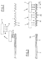
- the reference number 1 indicates a heat-formed blister strip which is conveyed continuously by means of known systems (not shown) in a direction of advancement W and at a predetermined operating speed.
- the dotted lines delimit identical portions 8 of blister strip 1 defining corresponding blister packs which will be formed in successive operating stations (not shown since they are not pertinent to the invention);
- the transversal outline of the blister strip 1 is defined by a whole number (3, in the example shown) of portions 8 of blister strip 1, while the cells 2 of each portion 8 of heat-formed strip 1 are reciprocally arranged at a first distance P1 longitudinally, and at a second distance P2 transversally to the extension of the strip 1.
- the reference number 30 is used generically to indicate an apparatus which is an object of this invention.
- the apparatus is arranged laterally near a section traversed by the blister strip 1, and comprises: a plurality of accumulation channels 3, which are rigidly constrained to a frame (not shown) of the apparatus 30 of the invention, articles 5 (for example pills, tablets, capsules and the like) being contained in line and in mutual contact in the channels, and destined to fill corresponding cells 2 of the blister strip 1; and a robotic device or organ 4, which is shown only schematically in the appended figures since it is substantially of a known type (see US 6-948.608 belonging to the Applicant); the organ 4 is of the three-axle type and is slidingly mounted on a guide 6 (see figure 1 ), which guide is constrained to the frame of the apparatus 30, parallel to the advancement direction W of the blister strip 1, and acts between the terminal sections 3A of the accumulation channels 3, where it collects a predetermined number of articles 5, and predetermined identical adjacent longitudinal regions R1, R2, R3 of the blister strip 1,
- the accumulation channels 3 are arranged inside container modules 7, are identical to each other, and are constrained to the frame; each module has the same number of accumulation channels 3 as the number of transversal rows 9 on a portion 8 of blister strip.
- the accumulation channels 3 (four in the example shown) contained within each module 7 are reciprocally parallel and are distanced by the same amount as the transversal rows 9 of cells 2 of a portion of blister strip 1, that is by the first distance P1.
- the container modules 7, of which a certain number is provided are distanced from one another by a distance P3 which is the same as the distance between the portions 8 ( figure 1 ), are arranged side by side, and are oriented perpendicular to the advancement direction W of the blister strip 1.
- the blister strip 1 is obtained by means of a series of heat-forming operating stages; each stage provides a longitudinal zone of heat-formed strip, which is constituted by a predetermined number of portions 8 which are oriented in transversal and longitudinal rows: advantageously the number of container modules 7 is the same as, or a multiple of, the number of portions 8 provided in a longitudinal row of each zone of heat-formed strip.
- the device 4 comprises gripping organs 70, for example sucker means, which are connected to a source of depression, and which collect a number of articles 5 from each accumulation channel 3 at the terminal sections 3A thereof, the number of articles 5 for each accumulation channel corresponding for example to the number of cells 2 on a transversal row of a portion 8 of blister strip 1 (three in the example shown).
- the regions R1, R2, R3 of blister strip 1 are identical, each being constituted by the same number of consecutively arranged portions 8 of blister strip 1 as the number of container modules 7 which are provided in the apparatus 30 (six in the example shown); the regions R1, R2, R3 are arranged adjacent to each other and all together define a complete longitudinal tract T of blister strip 1.
- the organs 70 also adjust the reciprocal transversal position of the articles 5 once these have been collected from the relative accumulation channels 3, so as to distance the articles 5 by the second distance P2 ( figures 2, 3 ) in the direction of reciprocal contact thereof, that is in the transversal direction, so that the spatial arrangement of the collected articles 5 corresponds perfectly to that of the empty cells 2 of the longitudinal region R1, R2, R3 which are to be filled.
- the apparatus 4 consequently positions itself above the advancing blister strip 1, follows the strip 1 and synchronises itself there-with in a centred position relative to the underlying corresponding longitudinal region R1, R2, R3, and then (after lowering, if necessary) releases the collected articles 5, suitably distanced from one another, into the corresponding empty cells 2 of the region R1, R2, R3.
- the maximum longitudinal travel which the apparatus 4 imposes on the organs 70 is indicated by E R .
- the functioning of the apparatus 30, which is an object of the present invention, is defined by the following description of the method for filling the cells of a heat-formed strip which the apparatus implements, the method also being an object of the invention.
- the method is destined to be implemented continuously and cyclically, a longitudinal tract T of the blister strip 1 being filled during the operations relative to each operating cycle; the blister strip 1, as mentioned above, is constituted in the shown example by the identical adjacent regions R1, R2, R3.
- the method includes:
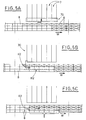
- the organs 70 are positioned above the blister strip and aligned with the first region R1, in their most retracted position K1 with reference to the maximum travel E R imposed on the organs 70 ( figure 4B ); subsequently the organs follow the strip until they are synchronised with the velocity of the strip, in a centred position relative to the region R1, and then they are lowered in order to allow release of the articles into the cells of the first region R1 ( figure 4C ).
- the organs 70 are positioned above the blister strip, and aligned with the second region R2, in an intermediate initial position K2, situated downstream of the retracted position K1 ( figure 5B ); the subsequent operations are the same as those described for the first region R1; in this way the articles are released into the cells of the second region R2 ( figure 5C ).
- the organs 70 are positioned above the blister strip, aligned with the third region R3, in an advanced position K3 which is situated downstream of the intermediate position K2: upon termination of the release of the articles into the cells of the third region R3 ( figure 6C ), the organs 70 are situated near the downstream end of their maximum travel E R .
- the third region R3 having been filled, the abovementioned operations are performed again, care being taken that the new regions R1*, R2*, R3* ( figure 6C ) are correspondingly arranged in good order behind the previous regions.
- the cells are filled by successively filling the cells of regions R1, R2, R3, which extend longitudinally, are mutually side-by-side and identical, and define an overall longitudinal tract T of the strip 1, all of the foregoing taking place with the strip 1 in continuous movement, which has positive effects on the productivity of the operation of filling the cells with articles.
- the number of articles which is collected by the organs 70 from each channel 3 is the same as the number of cells which is provided in each transversal row 9 of the portion 8 of the strip 1; this is extremely advantageous, since during each operating stage of the method, only the cells relative to portions 8, which will constitute corresponding blisters packs, are filled.
- the number of container modules 7 is the same as, or a multiple of, the number of portions 8 provided in a longitudinal row of each zone of strip which is obtained in each heat-forming stage the strip undergoes: this is advantageous for the reliability and productivity of the method provided; obviously the method can be implemented even if the number of modules does not fulfil the just-described condition.
- the parallel accumulation channels 3 which are contained inside each module 7 can also be arranged at a distance which differs from the first distance P1: in this case, the apparatus 30 will have organs 70 which are capable of suitably adjusting the position of the articles 5 which are collected from the accumulation channels 3 each time, so that the position of the articles 5 is the same as the spatial arrangement of the empty cells 2 of the region R1, R2, R3 to be filled.
- the advantage of this invention consists in having defined a method of new conception for filling the cells of a heat-formed strip, which method is constituted by an essential number of operating stages, and the implementation of which provides high reliability and productivity at relatively low costs compared with the advantages which are obtained.
- Another advantage of this invention consists of having defined an apparatus to implement the abovementioned method, which apparatus is reliable, functional, versatile and productive, the costs of which are low if compared with the advantages secured.
- the method which is an object of this invention and the apparatus which implements the method, also an object of the invention can be adapted to a wide range of applications, depending on the number of portions 8 of strip 1 identified transversally to the extension of the blister strip 1; and depending on the characteristics of each portion 8 of strip 1 in terms of the dimensions, number and arrangement of the cells 2 contained therein (the number of cells 2 for each relative longitudinal and transversal row).
- the regions of blister strip 1 which as a whole and on each occasion identify a specific longitudinal tract T of strip 1 can vary in terms of number and dimensions, according to production needs and requirements: in other words, instead of three regions R1, R2, R3 as in the example shown, the longitudinal portion T of the strip can be defined by two regions or by four or more regions, the cells of these regions being involved in the relative operating stages for filling as described above.
Landscapes
- Engineering & Computer Science (AREA)
- Mechanical Engineering (AREA)
- Containers And Plastic Fillers For Packaging (AREA)
- Separation Using Semi-Permeable Membranes (AREA)
Claims (12)
- Un procédé pour remplir des cellules d'une bande alvéolée avec des articles, la bande alvéolée (1) se déplaçant continuellement en avant dans une direction d'avancement (W) à une vitesse de fonctionnement préétablie, caractérisé en ce qu'il comporte, dans cet ordre:- la collecte simultanée d'une pluralité d'articles (5) en contact réciproque et disposés dans une pluralité de rangées parallèles (3) distinctes, le nombre d'articles (5) destinés à être collectés dans chaque rangée (3) correspondante étant prédéterminé;- l'ajustement des positions réciproques occupées par les articles (5) après leur collecte, de telle sorte que les articles (5) sont disposés selon le même arrangement spatial qu'un même nombre de cellules vides (2) d'une première portion longitudinale (R1) prédéterminée de la bande alvéolée (1);- le transfert des articles (5) collectés vers une position située au-dessus de la bande alvéolée et dans l'alignement de la première portion longitudinale (R1) à remplir, puis le transport des articles (5) dans la même direction que la direction d'avancement de la bande alvéolée (1) jusqu'à obtenir la synchronisation avec une vitesse de déplacement de la bande alvéolée (1), lesdits articles (5) étant centrés par rapport aux cellules (2) de la première portion sous-jacente (R1) ;- la libération des articles pour les introduire dans les cellules correspondantes (2) de la première portion (R1) ;- la répétition des phases ci-dessus afin de remplir les cellules (2) d'au moins une deuxième portion longitudinale (R2) de la bande alvéolée (1), ladite deuxième portion (R2) étant identique et contigüe à la première portion (R1), en complétant ainsi le remplissage des cellules d'un tronçon longitudinal (T) de la bande alvéolée (1) formé par la première et la seconde portions (R1, R2) ;- la répétition des phases de remplissage sur d'autres tronçons longitudinaux (T) consécutifs de la bande alvéolée.
- Le procédé selon la revendication 1, caractérisé en ce que la libération des articles (5) est précédée de leur descente vers la portion longitudinale (R1, R2) sous-jacente correspondante de la bande alvéolée.
- Le procédé selon la revendication 1, où les rangées parallèles (3) des articles (5) se trouvent réciproquement à une distance égale à l'espacement des rangées transversales (9) des cellules (2) de la première portion (R1) et de la deuxième portion (R2), et sont orientés perpendiculairement à la direction d'avancement de la bande alvéolée (1) thermoformée, caractérisé en ce que l'ajustement de la position réciproque occupée par les articles (5) collectés espace les articles (5) uniquement par rapport à la direction de contact mutuel, laquelle est transversale à la direction d'avancement de la bande alvéolée (1).
- Le procédé selon la revendication 1, caractérisé en ce que le nombre d'articles (5) collectés dans chaque rangée (3) est un sous-multiple du nombre de cellules (2) contenues dans une rangée transversale de la bande alvéolée (1).
- Un appareil pour remplir des cellules d'une bande thermoformée avec des articles, la bande thermoformée (1) se déplaçant continuellement en avant à une vitesse de préétablie dans une direction d'avancement (W), caractérisé en ce qu'il comprend :- une pluralité de canaux (3), qui sont limités par un cadre et qui contiennent des articles (5), disposés sur une rangée et qui, après être entrés en contact réciproque, s'accumulent près des parties terminales (3A) des canaux (3), lesdites parties terminales (3A) étant parallèles entre elles ; et- un dispositif (4), agissant entre les parties terminales (3A) des canaux d'accumulation (3) et les sections longitudinales identiques et contigües (R1, R2, R3) correspondantes de la bande alvéolée (1) qui avance, ledit dispositif (4) comprenant des organes de préhension (70) pour collecter les articles (5) contenus dans les canaux d'accumulation (3) et ajuster simultanément les positions réciproques occupées par les articles collectés (5), de telle sorte que lesdits articles (5) sont disposés selon le même arrangement spatial qu'un même nombre de cellules vides (2) d'une portion longitudinale (R1, R2, R3) prédéterminée de la bande alvéolée (1), les organes de préhension et d'ajustement (70) se positionnant au-dessus de la bande (1) et suivant la bande (1) jusqu'à ce que la vitesse soit synchronisée avec la vitesse de déplacement de la bande (1), en centrant les articles (5) par rapport aux cellules vides d'une portion longitudinale sous-jacente (R1, R2, R3) correspondante et en libérant enfin les articles (5) dans les cellules vides (2).
- L'appareil selon la revendication 5, caractérisé en ce que les parties terminales (3A) des canaux d'accumulation (3) se trouvent réciproquement à égale distance des rangées transversales (9) des cellules (2) des portions longitudinales (R1, R2, R3) de la bande alvéolée thermoformée (1).
- L'appareil selon la revendication 5, caractérisé en ce que les organes de préhension et d'ajustement (70) espacent les articles (5) uniquement dans une direction de contact mutuel des articles (5).
- L'appareil selon la revendication 5, caractérisé en ce que les organes de préhension et d'ajustement (70) du dispositif (4) collectent, dans chaque canal d'accumulation (3), des articles (5) dont le nombre est un sous-multiple du nombre de cellules (2) contenues dans une rangée transversale (9) de la bande alvéolée (1).
- L'appareil selon la revendication 5 ou 6, caractérisé en ce que les canaux d'accumulation (3) sont disposés sur les côtés de la bande alvéolée (1) et en ce que leurs parties terminales (3A) sont perpendiculaires à la direction d'avancement (W) de la bande alvéolée (1).
- L'appareil selon la revendication 5, 6 ou 9, avec des parties identiques (8) de la bande alvéolée (1) définies dans la bande alvéolée (1), lesdites parties identiques (8) présentant au moins une rangée longitudinale ou transversale de cellules (2), caractérisé en ce que les canaux d'accumulation (3) consistent en des contenants modulaires (7) en nombre égal au nombre de parties (8) de chacune des portions longitudinales (R1, R2, R3).
- L'appareil selon la revendication 10, caractérisé en ce que la distance (P3) entre les contenants modulaires (7) est égale à la distance entre les parties (8).
- L'appareil selon la revendication 10, caractérisé en ce que chaque contenant modulaire (7) contient le même nombre de canaux (3) que de rangées transversales (9) de la portion (8), et en ce que les canaux d'accumulation (3) sont espacés entre eux d'une distance (P1) égale à la distance entre les rangées transversales (9).
Applications Claiming Priority (1)
| Application Number | Priority Date | Filing Date | Title |
|---|---|---|---|
| IT000592A ITBO20070592A1 (it) | 2007-08-27 | 2007-08-27 | Metodo per il riempimento degli alveoli di un nastro alveolato con corrispondenti articoli ed apparato che attua tale metodo |
Publications (2)
| Publication Number | Publication Date |
|---|---|
| EP2030894A1 EP2030894A1 (fr) | 2009-03-04 |
| EP2030894B1 true EP2030894B1 (fr) | 2011-10-05 |
Family
ID=40039937
Family Applications (1)
| Application Number | Title | Priority Date | Filing Date |
|---|---|---|---|
| EP08161189A Not-in-force EP2030894B1 (fr) | 2007-08-27 | 2008-07-25 | Procédé et appareil pour remplir des cellules d'une bande alvéolée avec des articles |
Country Status (4)
| Country | Link |
|---|---|
| US (1) | US7770363B2 (fr) |
| EP (1) | EP2030894B1 (fr) |
| ES (1) | ES2374159T3 (fr) |
| IT (1) | ITBO20070592A1 (fr) |
Families Citing this family (10)
| Publication number | Priority date | Publication date | Assignee | Title |
|---|---|---|---|---|
| ITBO20070178A1 (it) * | 2007-03-14 | 2008-09-15 | Marchesini Group Spa | Dispositivo per il prelievo di articoli da una stazione di alimentazione e per il deposito degli stessi in corrispondenti alveoli di un nastro alveolato |
| IT1401851B1 (it) * | 2010-10-15 | 2013-08-28 | Marchesini Group Spa | Metodo per il trasferimento di articoli prelevati da piu' canali ad una linea di alimentazione di una macchina confezionatrice |
| NL2007384C2 (nl) | 2011-09-09 | 2013-03-12 | Ppm Engineering B V | Systeem en werkwijze voor het verpakken van gedoseerde hoeveelheden vaste medicijnen. |
| CN102730209A (zh) * | 2012-06-13 | 2012-10-17 | 苏州慧捷自动化科技有限公司 | 高精度万能组装填盘机 |
| PT2702979E (pt) | 2012-08-31 | 2015-09-10 | Carefusion Switzerland 317 Sarl | Um equipamento para empacotamento de quantidades receitadas de porções de medicamentos sólidos |
| US10351285B2 (en) | 2014-11-04 | 2019-07-16 | Mts Medication Technologies, Inc. | Systems and methods for automatically verifying packaging of solid pharmaceuticals via robotic technology according to patient prescription data |
| US10179664B2 (en) | 2014-11-05 | 2019-01-15 | Mts Medication Technologies, Inc. | Dispensing canisters for packaging oral solid pharmaceuticals via robotic technology according to patient prescription data |
| WO2018157231A1 (fr) * | 2017-03-01 | 2018-09-07 | Synergie Medicale Brg Inc. | Système de remplissage automatique d'organiseurs de médicaments |
| DE102017130735A1 (de) * | 2017-12-20 | 2019-06-27 | Delphi Salesconsulting Ag | Vorrichtung zur automatisierten Veränderung der Zusammensetzung eines Gemenges |
| EP3521185B1 (fr) * | 2018-02-05 | 2020-07-29 | Uhlmann Pac-Systeme GmbH & Co. KG | Procédé de commande de mouvement d'avance d'une feuille continue dans une machine d'emballage |
Family Cites Families (16)
| Publication number | Priority date | Publication date | Assignee | Title |
|---|---|---|---|---|
| US3499262A (en) * | 1968-02-14 | 1970-03-10 | Kaman Corp | Apparatus for packaging confectionery articles in individual receptacles and grouping the articles for transfer into an upwardly open box or the like |
| CH527732A (de) * | 1969-11-08 | 1972-09-15 | Haensel Otto Gmbh | Vorrichtung zum Einlegen von Süsswarenteilen, insbes. von Pralinen, in Verpackungseinsätze |
| US4677808A (en) * | 1984-03-15 | 1987-07-07 | Sapal, Societe Anonyme Des Plieuses Automatiques | Assembly for assorted packings with different products |
| DE3469875D1 (en) * | 1984-04-28 | 1988-04-21 | Sapal Plieuses Automatiques | Method and apparatus for the orderly introduction of articles, particularly pralines, into packaging containers |
| EP0163092B1 (fr) * | 1984-05-09 | 1988-03-30 | "LOESCH"-Verpackungstechnik GmbH & Co. KG | Dispositif pour déposer des pralines |
| US4667808A (en) * | 1985-06-17 | 1987-05-26 | Simplimatic Engineering Co. | Loading apparatus particularly useful for the loading or unstable containers |
| IT1190555B (it) * | 1986-03-19 | 1988-02-16 | Ferrero Spa | Dispositivo di presa particolarmente per apparecchiature automatiche di sollevamento e trasporto di impianti per il confezionamento di prodotti alimentari |
| DE4208818C2 (de) * | 1992-03-19 | 1994-09-08 | Haensel Otto Gmbh | Verfahren und Vorrichtung zum Einlegen von Artikeln in Verpackungseinsätze |
| US5611193A (en) * | 1995-01-31 | 1997-03-18 | Hudson Control Group, Inc. | Two-axis article loader/unloader |
| ITBO20000357A1 (it) | 2000-06-16 | 2001-12-16 | Marchesini Group Spa | Metodo per il trasferimento di confezioni blister e simili alla lineadi alimentazione di una macchina astucciatrice e dispositivo per attua |
| ITBO20020449A1 (it) * | 2002-07-12 | 2004-01-12 | Marchesini Group Spa | Metodo per la selezione e l'alimentazione di articoli ad un sottostante nastro alveolato ed apparecchiatura che attua tale metodo |
| ITBO20030753A1 (it) * | 2003-12-16 | 2005-06-17 | Packservice S R L | Dispositivo per il trasferimento di articoli in configurazione |
| DE102004006375A1 (de) * | 2004-02-09 | 2005-09-15 | Uhlmann Pac-Systeme Gmbh & Co Kg | Verfahren und Vorrichtung zum Überführen von Produkten aus einem Vorratsgefäß in die Näpfe einer Folie |
| DE102005049882B3 (de) | 2005-10-17 | 2007-02-01 | Uhlmann Pac-Systeme Gmbh & Co. Kg. | Vorrichtung zum geordneten Zuführen und Ablegen zu verpackender Kleinteile in die Näpfe einer Folienbahn |
| ITBO20070179A1 (it) * | 2007-03-14 | 2008-09-15 | Marchesini Group Spa | Dispositivo per il prelievo di articoli da una stazione di alimentazione e per l'inserimento degli stessi in un contenitore |
| ITBO20070178A1 (it) * | 2007-03-14 | 2008-09-15 | Marchesini Group Spa | Dispositivo per il prelievo di articoli da una stazione di alimentazione e per il deposito degli stessi in corrispondenti alveoli di un nastro alveolato |
-
2007
- 2007-08-27 IT IT000592A patent/ITBO20070592A1/it unknown
-
2008
- 2008-07-25 ES ES08161189T patent/ES2374159T3/es active Active
- 2008-07-25 EP EP08161189A patent/EP2030894B1/fr not_active Not-in-force
- 2008-07-29 US US12/181,444 patent/US7770363B2/en not_active Expired - Fee Related
Also Published As
| Publication number | Publication date |
|---|---|
| ITBO20070592A1 (it) | 2009-02-28 |
| EP2030894A1 (fr) | 2009-03-04 |
| ES2374159T3 (es) | 2012-02-14 |
| US20090056283A1 (en) | 2009-03-05 |
| US7770363B2 (en) | 2010-08-10 |
Similar Documents
| Publication | Publication Date | Title |
|---|---|---|
| US7770363B2 (en) | Method for filling cells of a blister strip with articles and an apparatus for implementing the method | |
| US6497083B1 (en) | Packaging apparatus | |
| US4932190A (en) | Method of and apparatus for assembling and wrapping arrays of cigarette packets and the like | |
| US20040173959A1 (en) | Conveying machines | |
| US10486914B2 (en) | Device and method for forming batches | |
| EP1970307B1 (fr) | Dispositif pour saisir des articles d'une station d'alimentation et les déposer dans les alvéoles correspondantes d'une bande de blisters. | |
| US7565781B2 (en) | Conveyor for feeding small objects to a blister-film loader | |
| US8668072B2 (en) | Machine and method for forming groups of products to be cased | |
| US20010003891A1 (en) | Method of and apparatus for accumulating and manipulating arrays of cigarettes and the like | |
| US9624042B2 (en) | Device and method for packaging tubes | |
| JPH04251022A (ja) | 物品の群を形成し移送する装置 | |
| CN109863089B (zh) | 用于扁平产品的份包装的方法和装置 | |
| CN108190818A (zh) | 一种抽真空充氮灌装机 | |
| EP3822178A1 (fr) | Machine et procédé d'emballage pour la production de cartouches jetables | |
| EP2193083B1 (fr) | Procédé et dispositif de remplissage d'emballages de type pliable | |
| US6347709B1 (en) | Method and apparatus for transferring packing units | |
| EP2846756B1 (fr) | Dispositif pour le remplissage de capsules | |
| EP3821732B1 (fr) | Machine et procede d'emballage pour la production de cartouches jetables | |
| CN202389622U (zh) | 一种高速包装机 | |
| US6397563B1 (en) | Method and device for packaging flat products | |
| EP4172044A2 (fr) | Machine d'emballage pour emballage horizontal et vertical d'articles dans une boîte d'emballage | |
| GB1271106A (en) | Assortment assembling apparatus, particularly for food products | |
| US20040195073A1 (en) | Assembly and method for collecting together different goods | |
| EP3822180B1 (fr) | Machine d'emballage et procédé d'emballage pour l'insertion de cartouches jetables dans des emballages coques correspondants | |
| EP2500284B1 (fr) | Machine de formation et de mise en boîte des groupes de cigarettes |
Legal Events
| Date | Code | Title | Description |
|---|---|---|---|
| PUAI | Public reference made under article 153(3) epc to a published international application that has entered the european phase |
Free format text: ORIGINAL CODE: 0009012 |
|
| AK | Designated contracting states |
Kind code of ref document: A1 Designated state(s): AT BE BG CH CY CZ DE DK EE ES FI FR GB GR HR HU IE IS IT LI LT LU LV MC MT NL NO PL PT RO SE SI SK TR |
|
| AX | Request for extension of the european patent |
Extension state: AL BA MK RS |
|
| 17P | Request for examination filed |
Effective date: 20090813 |
|
| AKX | Designation fees paid |
Designated state(s): DE ES FR IT |
|
| GRAP | Despatch of communication of intention to grant a patent |
Free format text: ORIGINAL CODE: EPIDOSNIGR1 |
|
| RIN1 | Information on inventor provided before grant (corrected) |
Inventor name: MONTI, GIUSEPPE |
|
| GRAS | Grant fee paid |
Free format text: ORIGINAL CODE: EPIDOSNIGR3 |
|
| GRAA | (expected) grant |
Free format text: ORIGINAL CODE: 0009210 |
|
| AK | Designated contracting states |
Kind code of ref document: B1 Designated state(s): DE ES FR IT |
|
| REG | Reference to a national code |
Ref country code: DE Ref legal event code: R096 Ref document number: 602008010218 Country of ref document: DE Effective date: 20111222 |
|
| REG | Reference to a national code |
Ref country code: ES Ref legal event code: FG2A Ref document number: 2374159 Country of ref document: ES Kind code of ref document: T3 Effective date: 20120214 |
|
| PLBE | No opposition filed within time limit |
Free format text: ORIGINAL CODE: 0009261 |
|
| STAA | Information on the status of an ep patent application or granted ep patent |
Free format text: STATUS: NO OPPOSITION FILED WITHIN TIME LIMIT |
|
| 26N | No opposition filed |
Effective date: 20120706 |
|
| REG | Reference to a national code |
Ref country code: DE Ref legal event code: R097 Ref document number: 602008010218 Country of ref document: DE Effective date: 20120706 |
|
| REG | Reference to a national code |
Ref country code: FR Ref legal event code: PLFP Year of fee payment: 9 |
|
| REG | Reference to a national code |
Ref country code: FR Ref legal event code: PLFP Year of fee payment: 10 |
|
| PGFP | Annual fee paid to national office [announced via postgrant information from national office to epo] |
Ref country code: ES Payment date: 20170801 Year of fee payment: 10 Ref country code: IT Payment date: 20170728 Year of fee payment: 10 Ref country code: DE Payment date: 20170727 Year of fee payment: 10 Ref country code: FR Payment date: 20170727 Year of fee payment: 10 |
|
| REG | Reference to a national code |
Ref country code: DE Ref legal event code: R119 Ref document number: 602008010218 Country of ref document: DE |
|
| PG25 | Lapsed in a contracting state [announced via postgrant information from national office to epo] |
Ref country code: FR Free format text: LAPSE BECAUSE OF NON-PAYMENT OF DUE FEES Effective date: 20180731 Ref country code: DE Free format text: LAPSE BECAUSE OF NON-PAYMENT OF DUE FEES Effective date: 20190201 |
|
| PG25 | Lapsed in a contracting state [announced via postgrant information from national office to epo] |
Ref country code: IT Free format text: LAPSE BECAUSE OF NON-PAYMENT OF DUE FEES Effective date: 20180725 |
|
| REG | Reference to a national code |
Ref country code: ES Ref legal event code: FD2A Effective date: 20190918 |
|
| PG25 | Lapsed in a contracting state [announced via postgrant information from national office to epo] |
Ref country code: ES Free format text: LAPSE BECAUSE OF NON-PAYMENT OF DUE FEES Effective date: 20180726 |
|
| P01 | Opt-out of the competence of the unified patent court (upc) registered |
Effective date: 20230331 |