EP2030923B1 - Appareil et procédé d'impression et/ou de balayage électronique de surfaces à double face d'une feuille/pli postal - Google Patents
Appareil et procédé d'impression et/ou de balayage électronique de surfaces à double face d'une feuille/pli postal Download PDFInfo
- Publication number
- EP2030923B1 EP2030923B1 EP08014931A EP08014931A EP2030923B1 EP 2030923 B1 EP2030923 B1 EP 2030923B1 EP 08014931 A EP08014931 A EP 08014931A EP 08014931 A EP08014931 A EP 08014931A EP 2030923 B1 EP2030923 B1 EP 2030923B1
- Authority
- EP
- European Patent Office
- Prior art keywords
- conveyor
- sheet material
- pressure differential
- face
- sheet
- Prior art date
- Legal status (The legal status is an assumption and is not a legal conclusion. Google has not performed a legal analysis and makes no representation as to the accuracy of the status listed.)
- Ceased
Links
- 230000009977 dual effect Effects 0.000 title description 5
- 238000000034 method Methods 0.000 title description 3
- 239000000463 material Substances 0.000 claims description 83
- 238000012546 transfer Methods 0.000 claims description 13
- 239000012530 fluid Substances 0.000 claims description 10
- 238000004891 communication Methods 0.000 claims description 8
- 230000007935 neutral effect Effects 0.000 claims description 4
- 238000012545 processing Methods 0.000 description 8
- 238000004519 manufacturing process Methods 0.000 description 3
- 230000008569 process Effects 0.000 description 2
- 238000011144 upstream manufacturing Methods 0.000 description 2
- 230000008859 change Effects 0.000 description 1
- 238000010276 construction Methods 0.000 description 1
- 238000011143 downstream manufacturing Methods 0.000 description 1
- 230000000694 effects Effects 0.000 description 1
- 239000004744 fabric Substances 0.000 description 1
- 230000008676 import Effects 0.000 description 1
- 238000003780 insertion Methods 0.000 description 1
- 230000037431 insertion Effects 0.000 description 1
- 230000007246 mechanism Effects 0.000 description 1
- 230000007704 transition Effects 0.000 description 1
Images



Classifications
-
- B—PERFORMING OPERATIONS; TRANSPORTING
- B65—CONVEYING; PACKING; STORING; HANDLING THIN OR FILAMENTARY MATERIAL
- B65H—HANDLING THIN OR FILAMENTARY MATERIAL, e.g. SHEETS, WEBS, CABLES
- B65H5/00—Feeding articles separated from piles; Feeding articles to machines
- B65H5/22—Feeding articles separated from piles; Feeding articles to machines by air-blast or suction device
- B65H5/222—Feeding articles separated from piles; Feeding articles to machines by air-blast or suction device by suction devices
- B65H5/224—Feeding articles separated from piles; Feeding articles to machines by air-blast or suction device by suction devices by suction belts
-
- B—PERFORMING OPERATIONS; TRANSPORTING
- B65—CONVEYING; PACKING; STORING; HANDLING THIN OR FILAMENTARY MATERIAL
- B65H—HANDLING THIN OR FILAMENTARY MATERIAL, e.g. SHEETS, WEBS, CABLES
- B65H11/00—Feed tables
- B65H11/007—Feed tables with front stop arrangements
-
- B—PERFORMING OPERATIONS; TRANSPORTING
- B65—CONVEYING; PACKING; STORING; HANDLING THIN OR FILAMENTARY MATERIAL
- B65H—HANDLING THIN OR FILAMENTARY MATERIAL, e.g. SHEETS, WEBS, CABLES
- B65H2301/00—Handling processes for sheets or webs
- B65H2301/30—Orientation, displacement, position of the handled material
- B65H2301/32—Orientation of handled material
- B65H2301/321—Standing on edge
-
- B—PERFORMING OPERATIONS; TRANSPORTING
- B65—CONVEYING; PACKING; STORING; HANDLING THIN OR FILAMENTARY MATERIAL
- B65H—HANDLING THIN OR FILAMENTARY MATERIAL, e.g. SHEETS, WEBS, CABLES
- B65H2301/00—Handling processes for sheets or webs
- B65H2301/40—Type of handling process
- B65H2301/44—Moving, forwarding, guiding material
- B65H2301/447—Moving, forwarding, guiding material transferring material between transport devices
- B65H2301/4473—Belts, endless moving elements on which the material is in surface contact
- B65H2301/44735—Belts, endless moving elements on which the material is in surface contact suction belt
-
- B—PERFORMING OPERATIONS; TRANSPORTING
- B65—CONVEYING; PACKING; STORING; HANDLING THIN OR FILAMENTARY MATERIAL
- B65H—HANDLING THIN OR FILAMENTARY MATERIAL, e.g. SHEETS, WEBS, CABLES
- B65H2701/00—Handled material; Storage means
- B65H2701/10—Handled articles or webs
- B65H2701/19—Specific article or web
- B65H2701/1916—Envelopes and articles of mail
-
- B—PERFORMING OPERATIONS; TRANSPORTING
- B65—CONVEYING; PACKING; STORING; HANDLING THIN OR FILAMENTARY MATERIAL
- B65H—HANDLING THIN OR FILAMENTARY MATERIAL, e.g. SHEETS, WEBS, CABLES
- B65H2801/00—Application field
- B65H2801/39—Scanning
Definitions
- This invention relates to apparatus for manipulating sheet material and, more particularly, to an apparatus for providing equal access to dual face surfaces of a sheet/mailpiece for printing/scanning on each side thereof.
- Material handling systems frequently require that sheet material, such as the internal mailpiece contents or mailpiece envelopes, be turned over to match a specific downstream requirement.
- mailpiece fabrication equipment typically requires that mailpiece content material be oriented face-up or face down depending upon the orientation of a receiving envelope This requirement has come under increasing demand as new and old equipment have, over the course of time, been merged. That is, some mailpiece fabrication systems require a face-up orientation while others employ a face-down presentation. Effective utilization and coordination of all systems/machines becomes inefficient when specific mailpiece fabrication jobs can only be processed on specific machines.
- US-A-6 139 004 describes a material strip handling apparatus comprising a lower vacuum conveyor and an upper vacuum conveyor.
- the lower vacuum conveyor conveys the strips of material which desirably are evenly spaced on the conveyance surface.
- the vacuum of the conveyor holds the strips of material with a controlled vacuum via a vacuum chamber.
- the vacuum of the lower conveyor holds the strips of material with a controlled vacuum to a tangent region of the lower vacuum conveyor with the upper vacuum conveyor.
- the strips of material are individually and successively transferred onto the upper vacuum conveyor.
- the vacuum of the lower vacuum conveyor is extinguished or otherwise ceases to hold the material strips thereto by vacuum means.
- a vacuum is created, generated or provided within the upper vacuum conveyor.
- Such vacuum may be so provided by means of a vacuum chamber or box and an associated vacuum-supplying hose or duct. The application of such a vacuum serves to hold the material strips adjacent the conveyance surface.
- various inversion modules have been developed to reorient the envelope or mailpiece content material for printing or scanning purposes. That is, a requirement often exists for a mailpiece envelope to have information printed on both face surfaces such as a destination address on one side thereof and a return address on the other side (typically on the rear face of the envelope flap). At other times, a sheet may have content material printed on one side while a destination address is printed on the opposite side such that, when folded, the destination address may be aligned with and seen through a transparent window of an envelope.
- One apparatus for inverting the orientation of a mailpiece envelope, or its content material includes a twist module wherein the sheet material is directed linearly along a spiral path, typically affected by a series of twisted belts or chords. While such twist modules retain the respective leading and trailing edge position of the sheet material, such modules require a lengthy axial path to change the face-up/ face-down orientation of the sheet material. Furthermore, twist modules are not reconfigurable to handle straight runs wherein sheet material inversion is not required. Consequently, a substitute module or entirely separate mechanism must be introduced to reconfigure the sheet material handling equipment.
- a sheet handling apparatus for conveying sheet material along a feed path, comprising, first and second conveyor modules having first and second conveyor surfaces, respectively, for driving the sheet material along the feed path, the conveyor modules being arranged such that at least a portion of the first conveyor surface opposes at least a portion of the second conveyor surface along a face-to-face interface; a means for developing a pressure differential across the first and second conveyor surfaces to hold the sheet material on one of the conveyor surfaces and transfer the sheet material from the first to the second conveyor surfaces during transport; and a processor operative to independently control the pressure differential means such that sheet material may be transferred from one conveyor module to the other conveyor module by controlling the pressure differential developed across each of the first and second conveyor surfaces when the sheet material is interposed between the face-to-face interface, wherein the first and second conveyor surfaces each include a plurality of openings therein, and wherein the pressure differential means associated with each of the first and second conveyor modules includes first and second pneumatic pump and a plenum defining first and second chambers disposed in
- a sheet handling apparatus for conveying sheet material/mailpieces along a feed path which facilitates access to the dual face surfaces thereof for the purpose of printing, and/or scanning information contained, thereon.
- the sheet handling apparatus includes first and second conveyor modules each having a conveyor surface, a portion of which is disposed in opposing, face-to-face relation with a portion of the other conveyor surface. Furthermore, the conveyor surfaces cooperate with a means for developing a pressure differential across the conveyor surfaces to hold the sheet material on the conveyor surfaces and transfer the sheet material across the modules during transport.
- a processor controls the pressure differential means such that the sheet material is held against the conveyor surfaces by a negative pressure differential developed across the conveyor surface and transferred from one conveyor surface to the other by controlling the pressure differential of both modules when the sheet material is interposed between the face-to-face interface. Furthermore, the remaining end portions of each conveyor surface are oppositely disposed and openly accessible to perform other sheet material processes. For example, the sheet material may be scanned along and/or printed on each face surface.
- sheet material means any page, document, or media wherein the dimensions and stiffness properties in a third dimension are but a small fraction, e.g., 1/100th of the dimensions and stiffness characteristics in the other two dimensions. As such, the sheet material is substantially "flat” and flexible about axes parallel to the plane of the sheet.
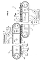
- FIG. 1 shows an isolated perspective view of the sheet handling apparatus 10 according to the present invention.
- the sheet handling apparatus 10 includes first and second conveyor modules 12, 14 each having roller-driven conveyor surfaces 12C, 14C, a means 16 for developing a pressure differential across the conveyor surfaces 12C, 14C of the conveyor modules 12, 14, and a processor 20 for independently controlling the pressure differential means 16.
- the conveyor modules 12, 14 are arranged such that an end portion of one conveyor surface 14C opposes the other conveyor surface 12C along a face-to-face interface FF. Furthermore, while the remaining portions 12EP, 14EP of the conveyor modules 12, 14 are diametrically opposite, i.e., 180° out-of-phase, the end portions 12EP, 14EP are openly accessible for other sheet material processes. The import of this arrangement/feature will be discussed in greater detail in subsequent paragraphs when discussing the operation for controlling the sheet handling apparatus.
- the conveyor surface 12C is composed of a flexible material which is porous or includes a plurality of openings/apertures 12CO to permit the passage of air therethrough.
- the conveyor surface 12C is furthermore, disposed about a pair of rollers 22, 24 to produce linear surface segments 26 between the rollers 22, 24.
- the rollers 22, 24 are driven in the direction of arrows D, though the motor(s) for driving the rollers 22, 24 is not shown.
- the means 16 for developing a pressure differential across the conveyor surface 12C includes, inter alia, one or more pneumatic pumps S 1 , S 2 and a plenum 30 disposed in fluid communication with the pneumatic pumps S 1 , S 2 ,.
- the plenum 30 is disposed between the linear segments 26 of the conveyor surface 12C and the rollers 22, 24 at each end of the conveyor module 12.
- the plenum 30 includes a plurality of apertures 30A disposed through a sidewall structure 30W of the plenum 30.
- the sidewall structure 30W is disposed adjacent the conveyor surface 12C and, in addition to tensile loads which may be imposed by the rollers 22, 24 on the conveyor surface 12C, the sidewall structure 30W provides a degree of lateral and/or vertical support for the conveyor surface 12C.
- the apertures 30A are sufficiently close to the conveyor surface 12C such that air/fluid will flow substantially normal to the conveyor surface 12C (i.e., through the openings 12CO) rather than in a direction parallel to and/or between the sidewall structure 30W and the interior conveyor surface 12C.
- the plenum 30 comprises at least one chamber 34-1, but may include additional chambers 34-2 to facilitate the transfer of sheet material from an upstream conveyor module 12 to a downstream conveyor module 14.
- additional chambers 34-2 to facilitate the transfer of sheet material from an upstream conveyor module 12 to a downstream conveyor module 14.
- the pneumatic pumps S 1 , S 2 are capable of generating a positive, negative and/or neutral pressure differential, P, V, N, respectively, across the conveyor surface 12C.
- a command or signal is issued by the processor 20 to the pneumatic pumps S 1 , S 2 to generate a vacuum V (see Fig. 2 ) or low pressure within one or both of the chambers 34-1, 34-2.
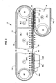
- FIGs 3 and 4 the operation for controlling the sheet handling apparatus 10 is depicted. While sheet material 40 may be adequately conveyed and handled by conveyor modules having a single-chambered plenum, the figures emphasize the advantages of a multi-chambered plenum 30 to enhance the control/transfer of sheet material from one conveyor module 12 to another module 14.
- sheet material 40 is introduced and is held against the conveyor surface 12C of the first conveyor module 12 by a vacuum V created in the chambers 34-1 and 34-2 of the plenum 30.
- the pressure differential is maintained across the conveyor surface 12C by the fluid communication established between the apertures 30A of the sidewall structure 30W and the openings 12CO of the conveyor surface 12C, i.e., even as the conveyor surface 13C slides across the sidewall surface 30W. Even as the conveyor surface 12C transitions from one chamber 34-1 to the next 34-2, the sheet material 40 continues to be urged against the conveyor surface 12C inasmuch as the pneumatic pump S 2 continues to draw a vacuum in the second chamber 34-2.
- a positive pressure differential P may be established in the second chamber 34-2 of the first conveyor module 12. More specifically, a negative pressure differential may be maintained in both first and second chambers 34-1, 34-2, via the first and second pneumatic pumps S 1 , S 2 until a sheet of material 40 has fully entered the interface region, between the first and second conveyors 12, 14.
- Various sensing apparatus may be employed, e.g., leading edge photo-optic sensors (not shown), to detect the position of the sheet material 40 along the feed path FP. When it is determined that the sheet material 40 is correctly positioned, the pneumatic pump S 2 converts to pressurize the chamber 34-2 and produce a positive pressure differential across the conveyor surface 12C.
- the sheet material 40 is urged from the conveyor surface 12C to the opposing conveyor surface 14C.
- the negative pressure differential maintains the sheet material 40 in position as it continues along the feed path, i.e., provided by the conveyor surface 14C of the second module 14.
- various processing devices may be disposed adjacent each of the accessible end portions 12EP, 14EP of the conveyor surfaces 12C, 14C.
- various mailpiece processing operations may be performed on the exposed face surfaces of the mailpieces.
- a first printer 50a (see Figs. 1 and 2 ) disposed adjacent the first exposed end portion 12EP of the first conveyor surface 12C may print a destination address on one side of a mailpiece envelope 54 traveling along the first conveyor surface 12C
- a second printer 50b disposed adjacent the second exposed end portion 14EP of the second conveyor surface 14C may print a return address on the opposite side of the envelope 54 as it travels along the second conveyor surface 14C.
- a first scanner 60a located adjacent to or substituting for the printer 50a
- the present invention provides an apparatus for transferring sheet material from one conveyor surface to another. Complexity is minimized and reliability optimized by reducing the number of moving parts. That is, aside from a common conveyor system, the apparatus employs a pneumatic system to hold, transfer and convey the sheet material. Moreover, the apparatus provides access to dual face surfaces of the sheet material, e.g., a mailpiece envelope, to perform various other processing operations such as printing and/or scanning.
- the sheet handling apparatus 10 is a device capable of transporting sheet material 40 along a co-planar feed path which prepares or presents the sheet material 40 in a suitable orientation for use by a downstream processing device. That is, the sheet handling apparatus 10 may be used to convey, transfer and deliver sheet material so as to present one face surface or another to a subsequent processing station including, but not limited to a printing and/or scanning station.
Landscapes
- Engineering & Computer Science (AREA)
- Mechanical Engineering (AREA)
- Delivering By Means Of Belts And Rollers (AREA)
- Separation, Sorting, Adjustment, Or Bending Of Sheets To Be Conveyed (AREA)
- Registering Or Overturning Sheets (AREA)
Claims (5)
- Appareil (10) de manipulation de feuilles pour transporter un matériau en feuille le long d'un trajet (FP) d'alimentation, comprenant,
des premier et deuxième modules (12, 14) de transport ayant des première et deuxième surfaces (12C, 14C) de transport, respectivement, pour entraîner le matériau en feuille le long du trajet d'alimentation, les modules (12, 14) de transport étant agencés de sorte qu'au moins une partie de la première surface (12C) de transport s'oppose à au moins une partie de la deuxième surface (14C) de transport le long d'une interface en face-à-face (FF);
un moyen (16) destiné au développement d'un différentiel de pression à travers les première et deuxième surfaces (12C, 14C) de transport pour maintenir le matériau en feuille sur l'une des surfaces de transport et transférer le matériau en feuille de la première à la deuxième surface de transport pendant le transport ; et
un processeur (20) fonctionnant pour commander indépendamment un moyen de différentiel de pression de sorte que le matériau en feuille puisse être transféré d'un module (12) de transport à l'autre module (14) de transport en commandant le différentiel de pression développé à travers chacune des première et deuxième surfaces (12C, 14C) de transport lorsque le matériau en feuille est interposé entre l'interface en face-à-face (FF),
dans lequel les première et deuxième surfaces (12C, 14C) de transport comportent chacune une pluralité d'ouvertures (12CO) dedans, et dans lequel le moyen de différentiel de pression associé à chacun des premier et deuxième modules de transport comporte des première et deuxième pompes (S1, S2) pneumatiques et un plénum (30) définissant des première et deuxième chambres (34-1, 34-2) agencées en communication par fluide avec des pompes (S1, S2) pneumatiques respectives, chaque chambre, en outre, définissant une structure (30W) de paroi latérale ayant une pluralité d'orifices (30A) disposés de manière adjacente à l'intérieur de la surface (12C, 14C) de transport respective de sorte que l'air puisse passer à travers les ouvertures de celle-ci et à travers les orifices (30A) du plénum pour produire un différentiel de pression à travers la surface de transport, la première pompe (S1) pneumatique étant disposée en communication par fluide avec la première chambre (34-1) et la deuxième pompe (S2) pneumatique étant disposée en communication par fluide avec la deuxième chambre (34-2), et dans lequel la deuxième pompe (S2) pneumatique est commandée indépendamment par le processeur (20) pour produire un différentiel de pression positif ou neutre à travers une partie de la surface de transport correspondant à l'interface en face-à-face pour transférer un matériau en feuille à partir d'un module (12) de transport à l'autre module (14) de transport. - Appareil de manipulation de feuilles selon la revendication 1, dans lequel un différentiel de pression négatif est développé à travers l'au moins une des surfaces (12C, 14C) de transport pour transporter le matériau en feuille le long du trajet (FP) d'alimentation.
- Appareil de manipulation de feuilles selon la revendication 2, dans lequel le différentiel de pression à travers la première surface de transport est neutralisé lorsqu'un différentiel de pression négatif est développé à travers la deuxième surface de transport pour transférer le matériau en feuille du premier au deuxième module de transport.
- Appareil de manipulation de feuilles selon la revendication 3, dans lequel le différentiel de pression à travers la première surface (12C) de transport est neutralisé lorsqu'un différentiel de pression négatif est développé à travers la deuxième surface de transport pour transférer le matériau en feuille du premier au deuxième module de transport le long de l'interface en face-à-face (FF).
- Appareil de manipulation de feuilles selon l'une quelconque des revendications précédentes, dans lequel les première et deuxième surfaces de transport définissent un trajet (FP) d'alimentation coplanaire essentiellement linéaire, pour transporter le matériau en feuille.
Applications Claiming Priority (1)
| Application Number | Priority Date | Filing Date | Title |
|---|---|---|---|
| US11/848,968 US20090057998A1 (en) | 2007-08-31 | 2007-08-31 | Apparatus and Method for Printing And/Or Electronically Scanning Dual Face Surfaces of a Sheet/Mailpiece |
Publications (3)
| Publication Number | Publication Date |
|---|---|
| EP2030923A2 EP2030923A2 (fr) | 2009-03-04 |
| EP2030923A3 EP2030923A3 (fr) | 2011-08-03 |
| EP2030923B1 true EP2030923B1 (fr) | 2012-10-03 |
Family
ID=40130542
Family Applications (1)
| Application Number | Title | Priority Date | Filing Date |
|---|---|---|---|
| EP08014931A Ceased EP2030923B1 (fr) | 2007-08-31 | 2008-08-22 | Appareil et procédé d'impression et/ou de balayage électronique de surfaces à double face d'une feuille/pli postal |
Country Status (2)
| Country | Link |
|---|---|
| US (1) | US20090057998A1 (fr) |
| EP (1) | EP2030923B1 (fr) |
Families Citing this family (7)
| Publication number | Priority date | Publication date | Assignee | Title |
|---|---|---|---|---|
| JP5246637B2 (ja) * | 2007-09-07 | 2013-07-24 | デュプロ精工株式会社 | 用紙反転装置 |
| US8091885B2 (en) * | 2009-07-10 | 2012-01-10 | Northrop Grumman Systems Corporation | Mail doubles detection and correction system |
| US8939274B1 (en) | 2014-01-15 | 2015-01-27 | Xante Corporation | Envelope feeder having dual aligned conveyors |
| EP3020559B1 (fr) * | 2014-11-13 | 2018-02-28 | OCE-Technologies B.V. | Mécanisme de transport et procédé pour transporter un support d'impression dans un système d'impression |
| US11254120B2 (en) * | 2018-08-30 | 2022-02-22 | Riso Kagaku Corporation | Conveyance device and image inspection device |
| US11313807B2 (en) * | 2018-08-30 | 2022-04-26 | Riso Kagaku Corporation | Image inspection device |
| EP3763646B1 (fr) * | 2019-07-11 | 2021-08-11 | Müller Apparatebau GmbH | Dispositif et procédé de transfert des feuilles entre des unités de transport |
Family Cites Families (11)
| Publication number | Priority date | Publication date | Assignee | Title |
|---|---|---|---|---|
| DE1561189B1 (de) * | 1967-05-26 | 1971-05-13 | Telefunken Patent | Einrichtung zur vereinzelten abgabe von flachen sendungen |
| DE1817101B2 (de) * | 1968-12-27 | 1972-04-13 | Telefunken Patentverwertungsgesellschaft Mbh, 7900 Ulm | Einrichtung zum vereinzeln von flachen sendungen wie insbesondere briefsendungen aus einem stapel |
| DE2620138A1 (de) * | 1976-05-07 | 1977-11-24 | Hoechst Ag | Blattfoerdervorrichtung fuer eine vervielfaeltigungsmaschine |
| DE3040021A1 (de) * | 1980-10-23 | 1982-05-13 | Windmöller & Hölscher, 4540 Lengerich | Vorrichtung zum bilden und stapeln von von einer folienschlauchbahn abgetrennten abschnitten |
| US5074547A (en) * | 1988-02-23 | 1991-12-24 | The Dow Chemical Company | Multiple delivery system |
| US5445369A (en) * | 1993-05-18 | 1995-08-29 | Golicz; Roman M. | Method of and apparatus for moving documents |
| DE4416286C2 (de) * | 1994-05-07 | 1999-10-28 | Heidelberger Druckmasch Ag | Vorrichtung zur Anpassung des Unterdruckes in einem Saugbandzuführtisch eines Bogenanlegers |
| DE19845214A1 (de) * | 1998-10-01 | 2000-04-06 | Heidelberger Druckmasch Ag | Druckmaschinenzylinder, insbesondere Gegendruckzylinder für eine Bogenrotationsmaschine |
| US6139004A (en) * | 1999-07-01 | 2000-10-31 | Kimberly-Clark Worldwide, Inc. | Assembly and method for rotating and placing strip of material on a substrate |
| DE10213705C5 (de) * | 2001-04-26 | 2017-01-05 | Heidelberger Druckmaschinen Ag | Vorrichtung zum Fördern eines Bogenstroms von einem Bogenstapel zu einer bogenverarbeitenden Maschine |
| US7014187B2 (en) * | 2003-06-12 | 2006-03-21 | Lockheed Martin Corporation | Vacuum plenum system for facilitating the high-speed conveyance of mail pieces |
-
2007
- 2007-08-31 US US11/848,968 patent/US20090057998A1/en not_active Abandoned
-
2008
- 2008-08-22 EP EP08014931A patent/EP2030923B1/fr not_active Ceased
Also Published As
| Publication number | Publication date |
|---|---|
| US20090057998A1 (en) | 2009-03-05 |
| EP2030923A2 (fr) | 2009-03-04 |
| EP2030923A3 (fr) | 2011-08-03 |
Similar Documents
| Publication | Publication Date | Title |
|---|---|---|
| EP2030923B1 (fr) | Appareil et procédé d'impression et/ou de balayage électronique de surfaces à double face d'une feuille/pli postal | |
| JP3868965B2 (ja) | 汎用で融通性のある複数プリンタ・複数仕上げ機シート統合システム | |
| US6572520B2 (en) | Apparatus for transporting envelope blanks in an envelope making machine | |
| JP4629447B2 (ja) | 印刷システム、及び印刷システム動作方法 | |
| US8540235B2 (en) | Conveying apparatus for envelopes and related methods | |
| JP4776991B2 (ja) | 多方向性通路モジュールを用いる可撓性の用紙の通路 | |
| US6102391A (en) | Right angle transfer apparatus | |
| US5554094A (en) | Folding apparatus | |
| US5318285A (en) | Roller/guide plate assembly for ninety degree document transfer unit | |
| US6164640A (en) | Apparatus for directionally reorienting sheets | |
| CA2472870C (fr) | Appareil et methode pour accumuler les feuilles | |
| US10160257B2 (en) | Orientation changing apparatus and enclosing-and-sealing system | |
| US7591454B2 (en) | Paper handling system material feed path arrangement | |
| JP2001139210A (ja) | 個々のシートを搬送及び排出するための装置 | |
| US8531699B2 (en) | Item transport system with pneumatic aligner | |
| EP2202190B1 (fr) | Appareil et procédé pour collecter des documents | |
| US7527262B2 (en) | Offsetting device for mail stackers | |
| US20100059335A1 (en) | Transporting apparatus for web products and related methods | |
| JPS6137102Y2 (fr) | ||
| JP3727612B2 (ja) | 書類処理装置および書類処理方法 | |
| JP2001097591A (ja) | 紙葉類搬送装置 | |
| CA2558631A1 (fr) | Appareil et methode pour accumuler les feuilles | |
| JP2008280096A (ja) | 用紙処理装置 | |
| JP2005066563A (ja) | 紙葉類処理装置 | |
| JPH07228393A (ja) | 紙葉類搬送装置 |
Legal Events
| Date | Code | Title | Description |
|---|---|---|---|
| PUAI | Public reference made under article 153(3) epc to a published international application that has entered the european phase |
Free format text: ORIGINAL CODE: 0009012 |
|
| AK | Designated contracting states |
Kind code of ref document: A2 Designated state(s): AT BE BG CH CY CZ DE DK EE ES FI FR GB GR HR HU IE IS IT LI LT LU LV MC MT NL NO PL PT RO SE SI SK TR |
|
| AX | Request for extension of the european patent |
Extension state: AL BA MK RS |
|
| PUAL | Search report despatched |
Free format text: ORIGINAL CODE: 0009013 |
|
| AK | Designated contracting states |
Kind code of ref document: A3 Designated state(s): AT BE BG CH CY CZ DE DK EE ES FI FR GB GR HR HU IE IS IT LI LT LU LV MC MT NL NO PL PT RO SE SI SK TR |
|
| AX | Request for extension of the european patent |
Extension state: AL BA MK RS |
|
| RIC1 | Information provided on ipc code assigned before grant |
Ipc: B65H 5/22 20060101AFI20110629BHEP |
|
| 17P | Request for examination filed |
Effective date: 20120125 |
|
| GRAP | Despatch of communication of intention to grant a patent |
Free format text: ORIGINAL CODE: EPIDOSNIGR1 |
|
| AKX | Designation fees paid |
Designated state(s): DE FR GB |
|
| GRAS | Grant fee paid |
Free format text: ORIGINAL CODE: EPIDOSNIGR3 |
|
| GRAA | (expected) grant |
Free format text: ORIGINAL CODE: 0009210 |
|
| AK | Designated contracting states |
Kind code of ref document: B1 Designated state(s): DE FR GB |
|
| REG | Reference to a national code |
Ref country code: GB Ref legal event code: FG4D |
|
| REG | Reference to a national code |
Ref country code: DE Ref legal event code: R096 Ref document number: 602008019095 Country of ref document: DE Effective date: 20121129 |
|
| PLBE | No opposition filed within time limit |
Free format text: ORIGINAL CODE: 0009261 |
|
| STAA | Information on the status of an ep patent application or granted ep patent |
Free format text: STATUS: NO OPPOSITION FILED WITHIN TIME LIMIT |
|
| 26N | No opposition filed |
Effective date: 20130704 |
|
| REG | Reference to a national code |
Ref country code: DE Ref legal event code: R097 Ref document number: 602008019095 Country of ref document: DE Effective date: 20130704 |
|
| REG | Reference to a national code |
Ref country code: FR Ref legal event code: PLFP Year of fee payment: 9 |
|
| REG | Reference to a national code |
Ref country code: FR Ref legal event code: PLFP Year of fee payment: 10 |
|
| REG | Reference to a national code |
Ref country code: FR Ref legal event code: PLFP Year of fee payment: 11 |
|
| PGFP | Annual fee paid to national office [announced via postgrant information from national office to epo] |
Ref country code: FR Payment date: 20180827 Year of fee payment: 11 Ref country code: DE Payment date: 20180829 Year of fee payment: 11 |
|
| PGFP | Annual fee paid to national office [announced via postgrant information from national office to epo] |
Ref country code: GB Payment date: 20180828 Year of fee payment: 11 |
|
| REG | Reference to a national code |
Ref country code: DE Ref legal event code: R082 Ref document number: 602008019095 Country of ref document: DE Representative=s name: HOFFMANN - EITLE PATENT- UND RECHTSANWAELTE PA, DE Ref country code: DE Ref legal event code: R081 Ref document number: 602008019095 Country of ref document: DE Owner name: DMT SOLUTIONS GLOBAL CORP. (N.D.GES.D. STAATES, US Free format text: FORMER OWNER: PITNEY BOWES, INC., STAMFORD, CONN., US |
|
| REG | Reference to a national code |
Ref country code: GB Ref legal event code: 732E Free format text: REGISTERED BETWEEN 20191128 AND 20191204 |
|
| REG | Reference to a national code |
Ref country code: DE Ref legal event code: R119 Ref document number: 602008019095 Country of ref document: DE |
|
| GBPC | Gb: european patent ceased through non-payment of renewal fee |
Effective date: 20190822 |
|
| PG25 | Lapsed in a contracting state [announced via postgrant information from national office to epo] |
Ref country code: DE Free format text: LAPSE BECAUSE OF NON-PAYMENT OF DUE FEES Effective date: 20200303 Ref country code: FR Free format text: LAPSE BECAUSE OF NON-PAYMENT OF DUE FEES Effective date: 20190831 |
|
| PG25 | Lapsed in a contracting state [announced via postgrant information from national office to epo] |
Ref country code: GB Free format text: LAPSE BECAUSE OF NON-PAYMENT OF DUE FEES Effective date: 20190822 |