EP2030945A2 - Gerbe destinée à la réception d'un liquide pouvant en être extrait, dotée d'une ouverture pour la réception d'un robinet de tirage - Google Patents
Gerbe destinée à la réception d'un liquide pouvant en être extrait, dotée d'une ouverture pour la réception d'un robinet de tirage Download PDFInfo
- Publication number
- EP2030945A2 EP2030945A2 EP08169909A EP08169909A EP2030945A2 EP 2030945 A2 EP2030945 A2 EP 2030945A2 EP 08169909 A EP08169909 A EP 08169909A EP 08169909 A EP08169909 A EP 08169909A EP 2030945 A2 EP2030945 A2 EP 2030945A2
- Authority
- EP
- European Patent Office
- Prior art keywords
- tube
- opening
- outer sleeve
- tap
- container
- Prior art date
- Legal status (The legal status is an assumption and is not a legal conclusion. Google has not performed a legal analysis and makes no representation as to the accuracy of the status listed.)
- Withdrawn
Links
- 239000007788 liquid Substances 0.000 title claims abstract description 57
- 230000001681 protective effect Effects 0.000 claims description 35
- 238000007789 sealing Methods 0.000 claims description 10
- 239000012530 fluid Substances 0.000 claims description 9
- 230000008878 coupling Effects 0.000 claims description 7
- 238000010168 coupling process Methods 0.000 claims description 7
- 238000005859 coupling reaction Methods 0.000 claims description 7
- 235000013361 beverage Nutrition 0.000 claims description 5
- 238000004891 communication Methods 0.000 claims description 3
- 230000001174 ascending effect Effects 0.000 abstract 1
- 239000011324 bead Substances 0.000 description 6
- 235000013405 beer Nutrition 0.000 description 5
- 238000010079 rubber tapping Methods 0.000 description 5
- 239000004033 plastic Substances 0.000 description 4
- 239000000463 material Substances 0.000 description 3
- 238000000034 method Methods 0.000 description 2
- 238000003825 pressing Methods 0.000 description 2
- 229910000831 Steel Inorganic materials 0.000 description 1
- 229910052782 aluminium Inorganic materials 0.000 description 1
- XAGFODPZIPBFFR-UHFFFAOYSA-N aluminium Chemical compound [Al] XAGFODPZIPBFFR-UHFFFAOYSA-N 0.000 description 1
- 238000005034 decoration Methods 0.000 description 1
- 230000001419 dependent effect Effects 0.000 description 1
- 230000000994 depressogenic effect Effects 0.000 description 1
- 230000000694 effects Effects 0.000 description 1
- 239000013013 elastic material Substances 0.000 description 1
- 230000002349 favourable effect Effects 0.000 description 1
- 239000011521 glass Substances 0.000 description 1
- 210000003127 knee Anatomy 0.000 description 1
- 238000004519 manufacturing process Methods 0.000 description 1
- 229910052751 metal Inorganic materials 0.000 description 1
- 239000002184 metal Substances 0.000 description 1
- 230000035515 penetration Effects 0.000 description 1
- 230000002093 peripheral effect Effects 0.000 description 1
- 230000003068 static effect Effects 0.000 description 1
- 239000010959 steel Substances 0.000 description 1
- 238000003860 storage Methods 0.000 description 1
- 239000002023 wood Substances 0.000 description 1
Images


Classifications
-
- B—PERFORMING OPERATIONS; TRANSPORTING
- B67—OPENING, CLOSING OR CLEANING BOTTLES, JARS OR SIMILAR CONTAINERS; LIQUID HANDLING
- B67D—DISPENSING, DELIVERING OR TRANSFERRING LIQUIDS, NOT OTHERWISE PROVIDED FOR
- B67D1/00—Apparatus or devices for dispensing beverages on draught
- B67D1/08—Details
- B67D1/12—Flow or pressure control devices or systems, e.g. valves, gas pressure control, level control in storage containers
- B67D1/14—Reducing valves or control taps
- B67D1/1405—Control taps
- B67D1/145—Control taps comprising a valve shutter movable in a direction perpendicular to the valve seat
- B67D1/1466—Control taps comprising a valve shutter movable in a direction perpendicular to the valve seat the valve shutter being opened in a direction opposite to the liquid flow
-
- B—PERFORMING OPERATIONS; TRANSPORTING
- B67—OPENING, CLOSING OR CLEANING BOTTLES, JARS OR SIMILAR CONTAINERS; LIQUID HANDLING
- B67D—DISPENSING, DELIVERING OR TRANSFERRING LIQUIDS, NOT OTHERWISE PROVIDED FOR
- B67D1/00—Apparatus or devices for dispensing beverages on draught
- B67D1/04—Apparatus utilising compressed air or other gas acting directly or indirectly on beverages in storage containers
- B67D1/0462—Squeezing collapsible or flexible beverage containers, e.g. bag-in-box containers
-
- B—PERFORMING OPERATIONS; TRANSPORTING
- B67—OPENING, CLOSING OR CLEANING BOTTLES, JARS OR SIMILAR CONTAINERS; LIQUID HANDLING
- B67D—DISPENSING, DELIVERING OR TRANSFERRING LIQUIDS, NOT OTHERWISE PROVIDED FOR
- B67D1/00—Apparatus or devices for dispensing beverages on draught
- B67D1/08—Details
- B67D1/0801—Details of beverage containers, e.g. casks, kegs
- B67D1/0802—Dip tubes
-
- B—PERFORMING OPERATIONS; TRANSPORTING
- B67—OPENING, CLOSING OR CLEANING BOTTLES, JARS OR SIMILAR CONTAINERS; LIQUID HANDLING
- B67D—DISPENSING, DELIVERING OR TRANSFERRING LIQUIDS, NOT OTHERWISE PROVIDED FOR
- B67D3/00—Apparatus or devices for controlling flow of liquids under gravity from storage containers for dispensing purposes
- B67D3/04—Liquid-dispensing taps or cocks adapted to seal and open tapping holes of casks, e.g. for beer
- B67D3/045—Liquid-dispensing taps or cocks adapted to seal and open tapping holes of casks, e.g. for beer with a closing element having a linear movement, in a direction parallel to the seat
-
- B—PERFORMING OPERATIONS; TRANSPORTING
- B67—OPENING, CLOSING OR CLEANING BOTTLES, JARS OR SIMILAR CONTAINERS; LIQUID HANDLING
- B67D—DISPENSING, DELIVERING OR TRANSFERRING LIQUIDS, NOT OTHERWISE PROVIDED FOR
- B67D1/00—Apparatus or devices for dispensing beverages on draught
- B67D1/08—Details
- B67D1/0801—Details of beverage containers, e.g. casks, kegs
- B67D2001/0822—Pressurised rigid containers, e.g. kegs, figals
- B67D2001/0824—Pressurised rigid containers, e.g. kegs, figals with dip tubes
Definitions
- the present invention is directed to a one-way dispensing tap for dispensing liquid from a pressurized liquid container modified from known dispensing taps so as to be preferably mounted in the upper portion of the side wall of the liquid container.
- the invention also relates to a liquid container with a corresponding opening for and with this tap.
- the inner tube further has an outlet opening, so that when the two inlet openings are above one another, liquid can enter the tap and can be tapped through the outlet opening. To close this tap, the inner tube must be fully reinserted into the outer tube.
- a disadvantage of this configuration is that to shut off the inner tube must always be pushed back into the outer tube after the pin. If the pipe slips, this can lead to unwanted liquid leakage.
- this nozzle comprises an outer tube and an inner tube which is slidably disposed in the outer tube.
- the liquid outlet opening is arranged in an outer region of the wall of the inner tube, which must be pulled out correspondingly far from the outer tube at the beginning of the first tapping operation.
- the actuator for this valve consists of an elastic button with a spout which engages around the bead of an extension of a valve stem, which in turn opens into the cone of the valve. Pressing the button opens the valve and liquid flows through the inner tube to the outlet. When the button is released, the valve closes due to the restoring force exerted by the elastic grommet surrounding the bead and supported by the internal pressure in the container.
- this opening is closed by means of a protective sheath sealingly pushed over the inner portion of the outer tube and having a smaller diameter tubular extension at the front.
- the inner tube is frontally provided with a pin which is dimensioned so that it extends in the initial state, in which the inner tube is fully inserted into the outer tube, in the tubular extension of the protective sheath and sealingly seals.
- a remainder hole is provided, which can be brought on further withdrawal of the inner tube with a corresponding bore with this to cover, so that liquid residues can get into the tap by tilting the container.
- a disadvantage of the systems described so far is that the nozzle must be located very far down in the side wall of the liquid container, so that the container can be emptied sufficiently. Due to the confined space below the tap, the container must be placed towards the spigot on a tapping trestle or table edge to allow liquid to be dispensed into a corresponding receptacle, e.g. a beer glass, to tap. It is therefore either easy to overturn or requires its own dedicated stand device. In addition, the pin is uncomfortable because of the low-lying tap.
- Such a system could be operated using an internal pressure reservoir or an internal pressurized gas cartridge.
- pressure sources are known in principle.
- the shows DE 298 22 430 a beverage container, eg a beer keg, in which a high-pressure bottle is positioned.
- a high pressure source in the center, on the bottom or on the lid of the drum.
- the proposed for such a system tap and possibly other accessories should therefore not extend too far into the middle of the container if possible, to allow the widest possible variety of mounting options for the pressure source.
- Object of the present invention is to provide a tap with the above-described as desirable requirement profile.
- a container / container for receiving a liquid dispensable therefrom which / which has a bottom side, a side wall and a lid or end face and an opening for attaching a tap and the / is characterized in that this opening is located in the side wall of the container / container, in an area which is closer to the top or end side than to the bottom side of the side wall.
- the opening is preferably mounted in the area above the peripheral bulge, which is modeled on a barrel hoop earlier wooden barrels, or in the absence such bulge at a height that corresponds to the so defined in the relation of the dimensions.
- the side wall has a single opening.
- the invention provides a tap that can be mounted in said opening of the liquid container, without appreciably occupy space, and with which you can tap with sufficient pressure within the container liquid even if the liquid level is lower than the tap even.
- the tap according to the invention is such according to claim 1 or claim 2 or a tap combination pipe according to claim 8.
- the dependent claims define preferred embodiments of this tap.
- the tap according to the invention can in principle be made of any material; however, it preferably consists of plastic and most preferably a combination of harder and more yielding plastic parts. It is completely manufactured and then used in the designated opening of the still empty liquid container, such as a 5 liter beer jar, sealing.
- the tap preferably has on its outer sleeve a latching mechanism, which may be formed as in the prior art.
- the outer sleeve carry two circumferential flanges or locking wedge-wreaths, between which there is a sealing ring.
- the edges of this opening come to rest on the seal and are held by the flanges or the locking wedge rings.
- the sealingly arranged in the inner channel of the outer sleeve tube is a sliding tube and has on its outwardly facing side a handle which is located in the mounted state outside the fluid container. In addition, it has near its axially outer end an outlet opening for the liquid to be tapped.
- the handle is designed so that by pulling and possibly also turning the sliding tube comfortably between a position in which the outlet opening protrudes from the outer sleeve, and a closed position in which the sliding tube is inserted into the sleeve so far that this Outlet opening completely covered, can be pulled. This process is usually required only once in the tap according to the invention, since Preferably, a valve device is provided, which prevents the operation of the free access of liquid to the outlet opening.
- the closed position in which the sliding tube is inserted so far into the sleeve that it completely covers the outlet opening, is generally identical to the state of the sliding tube that is completely inserted into the outer sleeve.
- locking can be realized in any way, for example by providing a sliding hole or opening in the outer Sleeve which can cooperate with a sliding block attached in the lower region of the sliding tube or the like.
- a sliding hole or opening in the outer Sleeve which can cooperate with a sliding block attached in the lower region of the sliding tube or the like.
- a channel-shaped recess may be provided, which serves as a guide for a corresponding locking tab.
- valve device if it is provided, also in a suitable manner as in DE 198 35 569 A1 be realized proposed.
- the valve itself is located within the slide tube at any point further inwardly relative to the outlet opening.
- it is arranged in the central region of the inner wall of the sliding tube and comprises, as in the DE 198 35 569 A1 described, a valve seat which is formed by an annular collar on the inside of the sliding tube and forms a conical seat, which can be sealed by means of a conical valve cone.
- This is connected to a valve stem or formed integrally therewith, wherein the valve stem in turn may be provided at its outside end with annular beads or grooves, which can cooperate with corresponding structures of a spout.
- the spout is elastic and can be integrally connected to an externally depressible bellows made of also elastic material such as rubber.
- an externally depressible bellows made of also elastic material such as rubber.
- the sliding tube has at its inner end side openings or openings through which the liquid to be tapped can get into the interior of the tube. This However, it should only be possible when the liquid container is put into use and the pin is started. Therefore, it is necessary to prevent the liquid from entering the pusher tube before starting a first tapping operation.
- this has a first, tubular part which is pushed onto an axially-facing inner end part of the outer sleeve (which in these embodiments is continuously tubular and open at its inner end) to the extent that said (n ), optionally existing opening (s) or bore (s) in the lateral region of the outer sleeve sealingly covered.
- the protective cover has an axially inwardly adjoining part with a tubular recess which can cooperate with a located on the inner end face of the sliding tube pin which projects beyond the pipe wall in the axial direction, such that in the fully inserted state of the sliding tube this pin sealingly closes said tubular recess.
- this part of the tap according to the invention is on the DE 198 35 569 A1 directed.
- the outer sleeve is shaped so that it can take over the functions of the protective cover. You should then have no side opening.
- the protective sleeve also has, as described above for the protective sleeve, an axially adjoining part with a tubular recess which can cooperate with a pin located on the inner end face of the sliding tube, which protrudes in the axial direction beyond the slider tube wall. that in the fully inserted state of the sliding tube this pin sealingly closes said tubular recess.
- the protective cover or the outer sleeve in the axial direction of the nozzle is closed at the front, but laterally has an opening which has a means for sealingly coupling a pipe or hose, which is to serve as a riser, and in the outwardly pushed state of the tube in Fluid communication with the interior of the sliding tube is.
- This opening can be configured in various ways.
- a protective sheath which follows the contour of the outer sleeve and an outer, annular region of the end face on the front side of the outer sleeve and then merges into a tube whose inside diameter said tubular Recess forms.
- this smaller diameter tube there is a lateral opening or recess surrounded by an annular bead or flange such that a tube or hose can be coupled thereto which should extend to the bottom of the fluid container and serves as a riser.
- This tube or hose can either be pulled outside over the annular bead or flange or inserted into this.
- the materials of both components or their diameters are selected to seal against each other under stiction.
- This embodiment can be realized in a second alternative without protective cover, when the outer sleeve is realized as described above. Then, there is a side opening or recess surrounded by an annular bead or flange in the above-described axially-inwardly-adjacent part of the outer sleeve having said tubular recess.
- the tubular recess of either the protective sheath or the correspondingly shaped outer sleeve opens in the axial direction in a channel which bent or knee-shaped leads to a laterally mounted opening in the protective sleeve or in the outer sleeve.
- both the protective cover and the outer sleeve, one-piece, but optionally also be formed in two parts, in the latter case, one of the parts of the protective cover, the first tubular part and the comprises tubular recess and the second part, which encloses the curved channel, may be configured as an adapter with a recess which can be pushed onto the outer wall of said tubular recess or otherwise secured thereto.
- the outer sleeve is either completely closed on the side completely, or it has only the already mentioned gate opening or a similar opening in connection with the locking of the sliding tube in the extended state, which is then covered by the protective cover. A residual emptying opening is not necessary.
- the retractable tap consists of seven or eight parts, namely an elastic cap which is integrally formed with said spout, a valve stem having an extension which cooperates in the manner described with the spout, a poppet, which can be slid onto and latched onto the valve lifter, the sliding tube with handle and, if necessary, a bore for the locking mechanism, for example the aforementioned link hole, the outer sleeve, an insert part which can be inserted into the inner muzzle of the sliding tube and the pin, frontal inlet openings for liquid and optionally components for the locking mechanism such as a sliding block comprises, and the one or two-piece protective cover.
- a tap with the features according to the invention fulfills the requirements set. It is protected against the ingress of liquid before first use. It has means for sealingly coupling a pipe or hose through which liquid is pressed into the tap at positive pressure in the container even when the liquid level is below the tap. He needs no residual emptying opening. And due to the fact that the coupling means for the pipe or hose is mounted laterally and thus can point downwards when installed, the tap can be used in combination with any pressurization systems, even if these are e.g. extend centrally from the cover or the inner top of the container further down than in the height in which the tap is mounted.
- the tap according to the invention can be used in combination with any container shapes and sizes. It is favorable for larger containers, eg with a capacity of 3I, 5I or more. In recent years, cans are also in of this size came into use.
- the tap can be used favorably in combination with so-called can kegs, which may be formed in two parts (container body from bottom wall and side wall with lid) or in three parts (bottom, side wall and lid), wherein the lid and possibly also the bottom of a common Doppelfalzver gleich or otherwise crimped on the container body or the side wall is / are.
- Such canned kegs can be modeled on that of old barrels; they often have a radially symmetric or approximately radially symmetric shape (eg with the wood structure of old barrels imitating polygonality). Decorations reminiscent of the old FassDelete can be mounted circumferentially at the corresponding locations of the side wall.
- the containers may stand on their floor or on a rim structure formed by the floor area.
- the tap according to the invention can then be arranged in an upper region of the side wall, so that the container or the can barrel is provided at its production with an opening in the side wall at the location provided for this purpose.
- FIG. 1 is an embodiment of the tap according to the invention according to claim 1 in conjunction with claim 6, that is, a tap 1 with a one-piece protective cover 16, which is shown in this figure in a detached state.
- the nozzle comprises an outer sleeve 2 with locking lugs 3 and a displaceably arranged in the sleeve 2 tube 4.
- the locking lugs are used for attachment to the liquid container.
- a pin 15 is attached at the inner end face 13 of the sliding tube 4, which has not visible in the figure inlet openings.
- this tube ends in the handle. 5
- the protective cover 16 is pushed with its tubular part 19 on the axially inner end portion 2 'of the outer sleeve (which has a slightly smaller outer diameter for this purpose than the remaining part) until the end face 13 of the sliding tube 4 abuts against the wall 24 , In this case, the tubular recess 20 of the protective cover sealingly engages around the pin 15. In this position, the tap is delivered and mounted.
- a lateral in the installed state downwardly facing opening 21, in whose side wall 22 a hose or a Hose coupling can be inserted.
- This hose serves as a riser, as in FIG. 7 shown.
- FIG. 2 shows an embodiment that is different from that of Fig. 1 differs in that the protective cover is formed in two parts, ie an embodiment according to claim 1 in conjunction with claim 7.
- the tap 1 corresponds to that of FIG. 1
- the protective cover consists of a first part 18 which has two tubular sections 19 ', 20'.
- the first of these parts has a diameter such that it can be slidably pushed onto the outer sleeve of the nozzle, while the second can sealingly enclose the pin 15.
- On the outer wall 24 ' can be an adapter 17 postpone.
- the pin 15 When the assembled dispensing tap is put into operation, the pin 15 is withdrawn from the recess 20 ', and there is a fluid connection between the downwardly facing opening 21' of the adapter and the inlet openings in the end wall 13 via the tubular knee 23 formed in the adapter part 25. Again, a hose or hose adapter or the like is inserted into the side wall 22 'of the opening 21' to provide a riser.
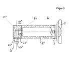
- FIG. 3 is an embodiment of the tap according to claim 2 in conjunction with claim 7 to see.
- the outer sleeve is formed in two parts.
- At the end of the first part 2 it has an extension 29, in which the tubular recess 20" for sealingly encompassing the pin 15 (not shown here) is located.
- an adapter 17 attached, which corresponds to the adapter 17, as in FIG. 2 is shown.
- an intermediate piece 28 is introduced, via which a riser tube or hose can be connected to the adapter.
- FIG. 4 shows a specific embodiment of a valve assembly, as it can be used in the tap according to the invention and from the DE 198 35 560 A1 is known. It can be seen in the wall of the sliding tube 4 annularly formed bulge 6, which cooperates with a conical valve cone 7. This is actuated by a valve stem 8, which has an annular recess 11 in its upper end into which an annular bulge 10 of a rubber grommet engages, which is integrally formed on a rubber bellows 9. It can be seen in this figure, the locking lugs 3 and a collar 30, which serve as a locking means for locking the tap in the container opening. For sealing a sealing means 29 is provided, which may for example consist of a resilient plastic material ring.
- FIG. 5 is the tap 1 according to FIG. 2 with the attached first part of the protective cover 18, but shown without adapter in the position in which the sliding tube 4 are pulled outwards, so that liquid can flow through inlet openings 13 'in the end face 13.
- the reference numerals correspond to those of FIGS. 1, 2 and 4 ,
- FIG. 6 is an embodiment of the tap with two-piece protective cover to see, however, as in FIG. 5 only the part 18 of the protective sheath is shown, which has small detent grooves 31 in its axial outer side in this figure.
- the locking of the sliding tube 4 is shown on the outer sleeve 2 by means of a link hole in cooperation with a sliding block, as set forth in the description.
- FIG. 7 shows a tap as in FIG. 3 shown, installed in a liquid container, which is a can barrel with circumferential bulges 33, which are modeled on former barrel hoops.
- the keg has a bottom part 37, a side wall 32 and a lid part 38; the tap is sealingly mounted in the side opening 36.
- a hose 34 is fastened to the opening 21 "via the intermediate piece 28 and serves as a riser pipe, the presence of a pressure reservoir 35 being indicated by dashed lines.
Landscapes
- Engineering & Computer Science (AREA)
- Mechanical Engineering (AREA)
- Containers And Packaging Bodies Having A Special Means To Remove Contents (AREA)
- Devices For Dispensing Beverages (AREA)
- Closures For Containers (AREA)
- Table Devices Or Equipment (AREA)
- Thermally Insulated Containers For Foods (AREA)
Priority Applications (1)
| Application Number | Priority Date | Filing Date | Title |
|---|---|---|---|
| EP08169909A EP2030945A3 (fr) | 2004-06-25 | 2005-06-24 | Gerbe destinée à la réception d'un liquide pouvant en être extrait, dotée d'une ouverture pour la réception d'un robinet de tirage |
Applications Claiming Priority (3)
| Application Number | Priority Date | Filing Date | Title |
|---|---|---|---|
| EP04014958 | 2004-06-25 | ||
| EP08169909A EP2030945A3 (fr) | 2004-06-25 | 2005-06-24 | Gerbe destinée à la réception d'un liquide pouvant en être extrait, dotée d'une ouverture pour la réception d'un robinet de tirage |
| EP05758391A EP1763486B1 (fr) | 2004-06-25 | 2005-06-24 | Robinet de prise a usage unique pour recipient de liquide sous pression |
Related Parent Applications (2)
| Application Number | Title | Priority Date | Filing Date |
|---|---|---|---|
| EP05758391A Division EP1763486B1 (fr) | 2004-06-25 | 2005-06-24 | Robinet de prise a usage unique pour recipient de liquide sous pression |
| EP05758391.6 Division | 2005-06-24 |
Publications (2)
| Publication Number | Publication Date |
|---|---|
| EP2030945A2 true EP2030945A2 (fr) | 2009-03-04 |
| EP2030945A3 EP2030945A3 (fr) | 2010-04-14 |
Family
ID=34925486
Family Applications (2)
| Application Number | Title | Priority Date | Filing Date |
|---|---|---|---|
| EP08169909A Withdrawn EP2030945A3 (fr) | 2004-06-25 | 2005-06-24 | Gerbe destinée à la réception d'un liquide pouvant en être extrait, dotée d'une ouverture pour la réception d'un robinet de tirage |
| EP05758391A Expired - Lifetime EP1763486B1 (fr) | 2004-06-25 | 2005-06-24 | Robinet de prise a usage unique pour recipient de liquide sous pression |
Family Applications After (1)
| Application Number | Title | Priority Date | Filing Date |
|---|---|---|---|
| EP05758391A Expired - Lifetime EP1763486B1 (fr) | 2004-06-25 | 2005-06-24 | Robinet de prise a usage unique pour recipient de liquide sous pression |
Country Status (11)
| Country | Link |
|---|---|
| US (1) | US8091745B2 (fr) |
| EP (2) | EP2030945A3 (fr) |
| CN (1) | CN101031498B (fr) |
| AT (1) | ATE421481T1 (fr) |
| AU (1) | AU2005256508B2 (fr) |
| CA (1) | CA2574257C (fr) |
| DE (3) | DE202005021165U1 (fr) |
| DK (1) | DK1763486T3 (fr) |
| ES (1) | ES2321018T3 (fr) |
| PL (1) | PL1763486T3 (fr) |
| WO (1) | WO2006000437A1 (fr) |
Families Citing this family (13)
| Publication number | Priority date | Publication date | Assignee | Title |
|---|---|---|---|---|
| DE102005022446B3 (de) * | 2005-05-14 | 2006-10-19 | Grittmann, Günter | Partyfass |
| NL1032893C2 (nl) * | 2006-11-17 | 2008-05-20 | Heineken Supply Chain Bv | Container voor het afgeven van drank. |
| EP1990309B1 (fr) * | 2007-05-09 | 2012-09-26 | Kurt Oberhofer | Récipient contenant une source de gaz sous pression de CO2 et protection anti-surpression |
| DE102009029453A1 (de) * | 2009-09-15 | 2011-03-24 | Plastic Solution Ningbo Patents Ltd. | Vorrichtung zur Aufnahme und Abgabe von Getränken |
| US20110226771A1 (en) * | 2010-03-17 | 2011-09-22 | Silgan Containers Llc | Container assembly with strainer |
| WO2011160658A1 (fr) * | 2010-06-22 | 2011-12-29 | Erwin Promoli | Robinet distributeur |
| NL2012469B1 (en) | 2014-03-18 | 2015-12-15 | Ipn Ip Bv | A liquid dispensing tap and liquid container provided with said tap. |
| US10036289B2 (en) | 2016-05-25 | 2018-07-31 | Honorio Y. Lim, Jr. | Oil level monitoring system |
| US12098010B2 (en) * | 2018-04-05 | 2024-09-24 | Square Keg, LLC | Container for storing, transporting and dispensing a beverage |
| DE102019207134A1 (de) * | 2019-05-16 | 2020-11-19 | Oam Gmbh | Getränkebehälter und eine Zapfeinrichtung für einen Getränkebehälter |
| DE102019213421A1 (de) * | 2019-09-04 | 2021-03-04 | Oam Gmbh | Zapfhahn und Behälter oder Bierfass mit einem Zapfhahn |
| EP3868704A1 (fr) * | 2020-02-18 | 2021-08-25 | AS Strömungstechnik GmbH | Tuyau pour un système de soutirage et procédé de soutirage du liquide d'un récipient au moyen d'un système de soutirage |
| US11873207B2 (en) * | 2021-11-30 | 2024-01-16 | World Wide Hagerty Inc. | Beverage-dispensing keg |
Citations (7)
| Publication number | Priority date | Publication date | Assignee | Title |
|---|---|---|---|---|
| US4923095A (en) | 1987-04-06 | 1990-05-08 | Adolph Coors Company | Apparatus and method for generating pressures for a disposable container |
| US5333763A (en) | 1992-10-30 | 1994-08-02 | Quoin Industrial Inc. | Pressure activation device |
| US5769282A (en) | 1996-04-12 | 1998-06-23 | Quoin Industrial, Inc. | Pressure generation system for a container |
| DE29822430U1 (de) | 1998-12-16 | 1999-04-01 | Schmalbach-Lubeca AG, 40880 Ratingen | Vorrichtung zum Positionieren einer Hochdruckflasche in Getränkebehältern |
| DE19825929A1 (de) | 1997-12-13 | 1999-06-17 | Huber Verpackungen Gmbh & Co | Zapfhahn zur Entnahme von Fluid aus einem Behälter |
| DE19835560A1 (de) | 1998-08-06 | 2000-02-10 | Volkswagen Ag | Kraftschluß-Verbindung |
| DE19835569A1 (de) | 1998-08-06 | 2000-02-17 | Guenter Grittmann | Versenkbarer Zapfhahn |
Family Cites Families (18)
| Publication number | Priority date | Publication date | Assignee | Title |
|---|---|---|---|---|
| US1080273A (en) * | 1911-05-11 | 1913-12-02 | Everlyn Albert Fountain | Telescopic bib-cock. |
| US1744216A (en) * | 1924-10-27 | 1930-01-21 | Draper Mfg Co | Faucet construction |
| BE371486A (fr) * | 1929-08-16 | |||
| GB342067A (en) * | 1929-12-06 | 1931-01-29 | Cornelius Chambers | Improvements in or relating to apparatus for dispensing liquids |
| US2112317A (en) * | 1937-12-29 | 1938-03-29 | Chancey M Valentine | Shipping and dispensing barrel |
| US2751119A (en) * | 1952-04-28 | 1956-06-19 | Sr Eugene S Manning | Milk bottle tap |
| US3039656A (en) * | 1958-12-11 | 1962-06-19 | Aircraft Armaments Inc | Extensible faucet for pressurized containers |
| US2992763A (en) * | 1959-07-31 | 1961-07-18 | Rufino O Huertas | Can faucet |
| US3243085A (en) * | 1962-07-05 | 1966-03-29 | Reynolds Metals Co | Dispensing container having a gas pressure container therein |
| US4742851A (en) * | 1986-07-17 | 1988-05-10 | The Coleman Company, Inc. | Dripless faucet for beverage containers |
| US4997108A (en) * | 1988-07-04 | 1991-03-05 | Hideaki Hata | Tap and liquid dispenser using the same |
| US5096092A (en) * | 1990-03-13 | 1992-03-17 | Mmm, Ltd. | Food dispensing apparatus utilizing inflatable bladder |
| US5110012A (en) * | 1991-01-11 | 1992-05-05 | Scholle Corporation | Beverage container with regulated pressure |
| CN2176339Y (zh) * | 1993-05-26 | 1994-09-07 | 青岛精工仪表厂 | 罐装饮料的提取龙头 |
| DE20212710U1 (de) * | 2002-08-19 | 2002-11-28 | Beuschel Dieter | Modifiziertes Fass mit ventilartigen Anschlüssen |
| DE102004047252A1 (de) * | 2004-09-29 | 2006-04-13 | Kurt Oberhofer | Flüssigkeitsbehälter |
| EP1688813A1 (fr) * | 2005-02-02 | 2006-08-09 | Impress GmbH & Co. oHG | Régulateur de pression avec dispositif de perçage pour cartouche de gas étant montable à l'intérieur de la fermeture d'un fût |
| DE102005022446B3 (de) * | 2005-05-14 | 2006-10-19 | Grittmann, Günter | Partyfass |
-
2005
- 2005-06-24 US US11/571,157 patent/US8091745B2/en not_active Expired - Fee Related
- 2005-06-24 DE DE202005021165U patent/DE202005021165U1/de not_active Expired - Lifetime
- 2005-06-24 WO PCT/EP2005/006857 patent/WO2006000437A1/fr not_active Ceased
- 2005-06-24 AU AU2005256508A patent/AU2005256508B2/en not_active Ceased
- 2005-06-24 CA CA2574257A patent/CA2574257C/fr not_active Expired - Lifetime
- 2005-06-24 PL PL05758391T patent/PL1763486T3/pl unknown
- 2005-06-24 AT AT05758391T patent/ATE421481T1/de active
- 2005-06-24 CN CN2005800285749A patent/CN101031498B/zh not_active Expired - Fee Related
- 2005-06-24 DE DE502005006540T patent/DE502005006540D1/de not_active Expired - Lifetime
- 2005-06-24 EP EP08169909A patent/EP2030945A3/fr not_active Withdrawn
- 2005-06-24 DK DK05758391T patent/DK1763486T3/da active
- 2005-06-24 EP EP05758391A patent/EP1763486B1/fr not_active Expired - Lifetime
- 2005-06-24 ES ES05758391T patent/ES2321018T3/es not_active Expired - Lifetime
- 2005-06-24 DE DE202005021164U patent/DE202005021164U1/de not_active Expired - Lifetime
Patent Citations (7)
| Publication number | Priority date | Publication date | Assignee | Title |
|---|---|---|---|---|
| US4923095A (en) | 1987-04-06 | 1990-05-08 | Adolph Coors Company | Apparatus and method for generating pressures for a disposable container |
| US5333763A (en) | 1992-10-30 | 1994-08-02 | Quoin Industrial Inc. | Pressure activation device |
| US5769282A (en) | 1996-04-12 | 1998-06-23 | Quoin Industrial, Inc. | Pressure generation system for a container |
| DE19825929A1 (de) | 1997-12-13 | 1999-06-17 | Huber Verpackungen Gmbh & Co | Zapfhahn zur Entnahme von Fluid aus einem Behälter |
| DE19835560A1 (de) | 1998-08-06 | 2000-02-10 | Volkswagen Ag | Kraftschluß-Verbindung |
| DE19835569A1 (de) | 1998-08-06 | 2000-02-17 | Guenter Grittmann | Versenkbarer Zapfhahn |
| DE29822430U1 (de) | 1998-12-16 | 1999-04-01 | Schmalbach-Lubeca AG, 40880 Ratingen | Vorrichtung zum Positionieren einer Hochdruckflasche in Getränkebehältern |
Also Published As
| Publication number | Publication date |
|---|---|
| EP2030945A3 (fr) | 2010-04-14 |
| ES2321018T3 (es) | 2009-06-01 |
| US8091745B2 (en) | 2012-01-10 |
| AU2005256508B2 (en) | 2010-09-23 |
| CN101031498A (zh) | 2007-09-05 |
| DE502005006540D1 (de) | 2009-03-12 |
| DE202005021165U1 (de) | 2007-05-31 |
| CA2574257A1 (fr) | 2006-01-05 |
| DK1763486T3 (da) | 2009-05-18 |
| CA2574257C (fr) | 2013-12-17 |
| ATE421481T1 (de) | 2009-02-15 |
| WO2006000437A1 (fr) | 2006-01-05 |
| AU2005256508A1 (en) | 2006-01-05 |
| EP1763486B1 (fr) | 2009-01-21 |
| EP1763486A1 (fr) | 2007-03-21 |
| DE202005021164U1 (de) | 2007-06-06 |
| PL1763486T3 (pl) | 2009-09-30 |
| CN101031498B (zh) | 2011-08-24 |
| US20080041892A1 (en) | 2008-02-21 |
Similar Documents
| Publication | Publication Date | Title |
|---|---|---|
| EP2121505B1 (fr) | Dispositif de débit de boisson de type un fût jetable | |
| EP0912407B1 (fr) | Contenant de liquides pour boissons, tel que canette, tonnelet pour fetes ou fut | |
| DE60209540T2 (de) | Zapfventil | |
| EP1763486B1 (fr) | Robinet de prise a usage unique pour recipient de liquide sous pression | |
| EP1102719B1 (fr) | Cannelle escamotable | |
| DE1411626A1 (de) | Einwandiger Metallbehaelter,insbesondere Bierfass | |
| DE102005022446B3 (de) | Partyfass | |
| DE10113109A1 (de) | Verschließbare Abgabevorrichtung zur Abgabe eines in einem Behälter enthaltenen flüssigen, viskosen oder pastösen Mediums | |
| EP0270878B1 (fr) | Dispositif pour soutirer de la bière à partir de récipients, notamment de tonnelets | |
| DE60212360T2 (de) | Vorrichtung zur dosierten abgabe von flüssigen oder gelförmigen medien | |
| EP2384307B1 (fr) | Dispositif de soutirage | |
| EP2295372B1 (fr) | Chapiteau destiné à tirer par pression pour conteneur à bière et procédé de fonctionnement de celui-ci | |
| EP1648813A1 (fr) | Restricteur de mousse | |
| EP3216751B1 (fr) | Dispositif de soutirage, fût et procédé de soutirage | |
| EP2358628B1 (fr) | Contenant et procédé de remplissage d'un contenant | |
| DE10200748A1 (de) | Verschließbare Abgabevorrichtung zur Abgabe eines in einem Behälter enthaltenen flüssigen, viskosen oder pastösen Mediums | |
| DE29722034U1 (de) | Behälter für Flüssigkeiten, insbesondere Getränke | |
| WO2017129176A1 (fr) | Dispositif de fermeture de récipients | |
| DE10028527C2 (de) | Verschluss mit einem Ausgießer für Behälter | |
| DE9300928U1 (de) | Flaschenzapfanlage | |
| DE29623783U1 (de) | Flüssigkeitsbehälter für Getränke, wie Dose, Partyfaß oder Gebinde | |
| DE1186769B (de) | Vorrichtung zum Ausschenken fuer unter Druck stehende Fluessigkeiten, beispielsweise Bier | |
| WO1999031008A1 (fr) | Contenant et robinet de prise pour liquides, en particulier pour boissons | |
| DE102011004393A1 (de) | Verschlusseinrichtung für einen Getränkebehälter | |
| DE1532652B1 (de) | Zapfvorrichtung zum Aufsetzen auf einen Spundlochverschluss |
Legal Events
| Date | Code | Title | Description |
|---|---|---|---|
| PUAI | Public reference made under article 153(3) epc to a published international application that has entered the european phase |
Free format text: ORIGINAL CODE: 0009012 |
|
| AC | Divisional application: reference to earlier application |
Ref document number: 1763486 Country of ref document: EP Kind code of ref document: P |
|
| AK | Designated contracting states |
Kind code of ref document: A2 Designated state(s): AT BE BG CH CY CZ DE DK EE ES FI FR GB GR HU IE IS IT LI LT LU MC NL PL PT RO SE SI SK TR |
|
| AX | Request for extension of the european patent |
Extension state: AL BA HR LV MK YU |
|
| PUAL | Search report despatched |
Free format text: ORIGINAL CODE: 0009013 |
|
| AK | Designated contracting states |
Kind code of ref document: A3 Designated state(s): AT BE BG CH CY CZ DE DK EE ES FI FR GB GR HU IE IS IT LI LT LU MC NL PL PT RO SE SI SK TR |
|
| AX | Request for extension of the european patent |
Extension state: AL BA HR LV MK YU |
|
| RIC1 | Information provided on ipc code assigned before grant |
Ipc: B65D 1/20 20060101ALI20100305BHEP Ipc: B67D 1/08 20060101ALI20100305BHEP Ipc: B67D 1/04 20060101ALI20100305BHEP Ipc: B67D 3/04 20060101ALI20100305BHEP Ipc: B67D 1/14 20060101AFI20090120BHEP |
|
| AKY | No designation fees paid | ||
| STAA | Information on the status of an ep patent application or granted ep patent |
Free format text: STATUS: THE APPLICATION IS DEEMED TO BE WITHDRAWN |
|
| 18D | Application deemed to be withdrawn |
Effective date: 20101015 |