EP2031208A2 - Axialgebläse zum Kühlen der unteren Motorhaube einer Landwirtschaftsmaschine - Google Patents
Axialgebläse zum Kühlen der unteren Motorhaube einer Landwirtschaftsmaschine Download PDFInfo
- Publication number
- EP2031208A2 EP2031208A2 EP08162261A EP08162261A EP2031208A2 EP 2031208 A2 EP2031208 A2 EP 2031208A2 EP 08162261 A EP08162261 A EP 08162261A EP 08162261 A EP08162261 A EP 08162261A EP 2031208 A2 EP2031208 A2 EP 2031208A2
- Authority
- EP
- European Patent Office
- Prior art keywords
- axial fan
- chord
- main profile
- profile
- rotor
- Prior art date
- Legal status (The legal status is an assumption and is not a legal conclusion. Google has not performed a legal analysis and makes no representation as to the accuracy of the status listed.)
- Withdrawn
Links
- 238000001816 cooling Methods 0.000 title claims abstract description 20
- 238000011161 development Methods 0.000 claims abstract description 3
- 238000005259 measurement Methods 0.000 claims description 5
- 238000005452 bending Methods 0.000 claims description 3
- 238000000926 separation method Methods 0.000 abstract description 2
- 238000010586 diagram Methods 0.000 description 4
- 238000009826 distribution Methods 0.000 description 4
- 230000003068 static effect Effects 0.000 description 4
- 230000000052 comparative effect Effects 0.000 description 2
- 238000004519 manufacturing process Methods 0.000 description 2
- 238000012545 processing Methods 0.000 description 2
- 238000001228 spectrum Methods 0.000 description 2
- 238000010521 absorption reaction Methods 0.000 description 1
- 230000001133 acceleration Effects 0.000 description 1
- 230000002730 additional effect Effects 0.000 description 1
- 230000005540 biological transmission Effects 0.000 description 1
- 238000004364 calculation method Methods 0.000 description 1
- 238000002485 combustion reaction Methods 0.000 description 1
- 230000003750 conditioning effect Effects 0.000 description 1
- 238000009795 derivation Methods 0.000 description 1
- 239000002283 diesel fuel Substances 0.000 description 1
- 238000007599 discharging Methods 0.000 description 1
- 230000000694 effects Effects 0.000 description 1
- 238000002474 experimental method Methods 0.000 description 1
- 239000012530 fluid Substances 0.000 description 1
- 239000007788 liquid Substances 0.000 description 1
- 239000000463 material Substances 0.000 description 1
- 238000012986 modification Methods 0.000 description 1
- 230000004048 modification Effects 0.000 description 1
- 238000011160 research Methods 0.000 description 1
- 238000004088 simulation Methods 0.000 description 1
- 238000012360 testing method Methods 0.000 description 1
- 238000011144 upstream manufacturing Methods 0.000 description 1
- 238000009423 ventilation Methods 0.000 description 1
Images

Classifications
-
- F—MECHANICAL ENGINEERING; LIGHTING; HEATING; WEAPONS; BLASTING
- F01—MACHINES OR ENGINES IN GENERAL; ENGINE PLANTS IN GENERAL; STEAM ENGINES
- F01P—COOLING OF MACHINES OR ENGINES IN GENERAL; COOLING OF INTERNAL-COMBUSTION ENGINES
- F01P5/00—Pumping cooling-air or liquid coolants
- F01P5/02—Pumping cooling-air; Arrangements of cooling-air pumps, e.g. fans or blowers
-
- F—MECHANICAL ENGINEERING; LIGHTING; HEATING; WEAPONS; BLASTING
- F04—POSITIVE - DISPLACEMENT MACHINES FOR LIQUIDS; PUMPS FOR LIQUIDS OR ELASTIC FLUIDS
- F04D—NON-POSITIVE-DISPLACEMENT PUMPS
- F04D29/00—Details, component parts, or accessories
- F04D29/26—Rotors specially for elastic fluids
- F04D29/32—Rotors specially for elastic fluids for axial flow pumps
- F04D29/325—Rotors specially for elastic fluids for axial flow pumps for axial flow fans
- F04D29/326—Rotors specially for elastic fluids for axial flow pumps for axial flow fans comprising a rotating shroud
-
- F—MECHANICAL ENGINEERING; LIGHTING; HEATING; WEAPONS; BLASTING
- F04—POSITIVE - DISPLACEMENT MACHINES FOR LIQUIDS; PUMPS FOR LIQUIDS OR ELASTIC FLUIDS
- F04D—NON-POSITIVE-DISPLACEMENT PUMPS
- F04D29/00—Details, component parts, or accessories
- F04D29/26—Rotors specially for elastic fluids
- F04D29/32—Rotors specially for elastic fluids for axial flow pumps
- F04D29/325—Rotors specially for elastic fluids for axial flow pumps for axial flow fans
- F04D29/327—Rotors specially for elastic fluids for axial flow pumps for axial flow fans with non identical blades
-
- F—MECHANICAL ENGINEERING; LIGHTING; HEATING; WEAPONS; BLASTING
- F04—POSITIVE - DISPLACEMENT MACHINES FOR LIQUIDS; PUMPS FOR LIQUIDS OR ELASTIC FLUIDS
- F04D—NON-POSITIVE-DISPLACEMENT PUMPS
- F04D29/00—Details, component parts, or accessories
- F04D29/26—Rotors specially for elastic fluids
- F04D29/32—Rotors specially for elastic fluids for axial flow pumps
- F04D29/38—Blades
- F04D29/384—Blades characterised by form
-
- F—MECHANICAL ENGINEERING; LIGHTING; HEATING; WEAPONS; BLASTING
- F04—POSITIVE - DISPLACEMENT MACHINES FOR LIQUIDS; PUMPS FOR LIQUIDS OR ELASTIC FLUIDS
- F04D—NON-POSITIVE-DISPLACEMENT PUMPS
- F04D29/00—Details, component parts, or accessories
- F04D29/26—Rotors specially for elastic fluids
- F04D29/32—Rotors specially for elastic fluids for axial flow pumps
- F04D29/38—Blades
- F04D29/388—Blades characterised by construction
Definitions
- the present invention refers to an axial fan for cooling the underhood of farm machines and earthmovers in general.
- the underhood of modern farm machines is characterised by the simultaneous presence of several radiating elements not only intended for cooling the engine, but also for cooling the oil present in the transmission and hydraulic system.
- the condenser of the cockpit conditioning system is almost always present on the farm machines.
- intercooler An element becoming more and more indispensable to allow farm machines equipped with turbocharged engines meet the requirements provided for by the antipollution directives in force is the so-called "intercooler", that is an air/air or air/liquid heat exchanger of a quite considerable size, in that the temperature of the comburant air entering the engine must not exceed the value of 50°C.
- diesel fuel radiator which is essential to ensure that the power supplied by the engine is the most constant possible, regardless of the high temperatures that the modern internal combustion engines are capable of reaching during their operation cycle.
- an object of the present invention is that of overcoming the problems of the prior art, by providing a fan of the axial type for cooling the underhood of a farm machine, capable of providing better performances, considering the same air-flow, with respect to fans of the traditional type.
- Another object of the invention is that of providing an axial fan for cooling the underhood of a farm machine, capable of containing - during its operation - the occurrence of turbulent phenomena in the cooling air-flow, with the consequent reduction of the noise and the power absorbed.
- Another object of the invention is that of providing an axial fan for cooling the underhood of a farm machine which is simple and inexpensive to manufacture.
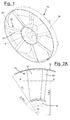
- FIG 1 shown is an example of an embodiment of an axial fan according to the present invention, indicated in its entirety with reference number 10.
- the fan 10 made in the form of a disk or rotor, is configured in particular but not exclusively to carry out the cooling of the underhood (not shown) of a generic farm machine, such as for example a farm tractor, a combine harvester or the like.
- the rotor 10 is provided with a plurality of blades 12, with a wing profile and a substantially radial development, constrained against the central hub 14 of the rotor 10 itself at one of their first ends. Furthermore, the rotor 10 has an external circumferential edge 16 constrained against which is the other end of each blade 12.
- each blade 12 is made up of a profile of the multiple type, that is characterised by the presence of a first element or main profile 18 and at least the presence of one further element or flap 20 arranged in proximity to the inlet edge 18', also referred to by the term of aviation derivation "slat", of the main profile 18 itself.
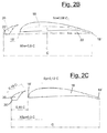
- Figures 2B and 2C both show a sectional view of the blade profile 12, obtained at a distance from the central axis of the rotor 10 equivalent to 1.6 times the chord C in the axial direction of the rotor 10 itself.
- the chord C is defined as the linear distance between the inlet edge 20' of the flap 20 and the outlet edge 18" of the main profile 18.
- the radius of the rotor 10 is equivalent to about two times the length of the chord C, while the radius of the central hub 14 is equivalent to about 75% of the length of the chord C itself.
- the main profile 18 is characterised by a median line 22 having a relative maximum deflection fm equivalent to about 6% with respect to the length of the chord C, wherein the point Xfm of maximum bending is identified at 50% or, in other words, in proximity to the centreline point of the chord C itself.
- the main profile 18 has a maximum value equivalent to 12% of the length of the chord C in proximity to 30% of the length of the chord C itself, with measurement taken starting from the inlet edge 20' of the flap 20.
- the purpose of the flap 20 is that of extending the field of correct functionality of the main profile 18 with considerably critical angles of attack.
- Research for elevated work values per mass unit required to the fan 10, within the scope of applications herein referred to, requires very high blade keying angles of the blade profile 12 (35° ⁇ 42° at the root of the blade) and, thus, the use of more sophisticated wing sections like the one according to the present invention.
- the valuable function of "controlling the boundary layer" performed by the blade profile 12 made up of two distinct elements 18 and 20 is not only useful from an aerodynamic point of view, but also from an acoustic point of view (discussed hereinafter), in that the reduction of important turbulent structures at the edge of the outlet 18" of the blade profile 12 has a positive impact on the aero-acoustic behaviour of the fan 10.
- figure 3 allows showing the considerable acceleration received by the air-flow when crossing the space comprised between the two wing elements.
- Such increase of speed allows the flow along the side in depression to advance, without any risks of separation, towards the outlet edge 18".
- the trail zone (at a low speed) is slightly thicker than the outlet edge itself, to the advantage of the aeraulic performances.
- the low turbulence of the flow upon discharge is an indicator of low noise as a consequence of a lower dissipation of energy to the detriment of the processed flow.
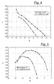
- Figures 4 and 5 illustrate the distributions of the work and efficiency, depending on the amount processed, of a traditional rotor with respect to the rotor 10 according to the present invention.
- the results observed from the acoustic calculations carried out shall be discussed hereinafter.
- figure 3 shows the trend of the coefficient of static work ⁇ depending on the flow coefficient ⁇ .
- figure 4 allows comparing two different distributions of parameters ⁇ and ⁇ defined beforehand, according to the dimensions measured through experimental surveys carried out on the fan 10 according to the invention and on a fan of the conventional type but with good performances.
- the characteristic curve of the new fan 10 indicates better performances with respect to the ones of the traditional fan, with differences in terms of work (and thus in terms of static pressure) whenever higher that 20% considering the same amount of processed flow.
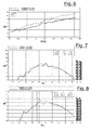
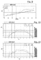
- FIGS. 6-11 Represented in figures 6-11 are the diagrams regarding the comparative noise measurements between the fan 10 according to the invention and the reference axial fan.
- the abovementioned experimental surveys were obtained by positioning the fans into the underhood of a purposely equipped farm tractor.
- subject of the survey in a temporary and direct manner, was the rotation speed of the engine and of the fan alongside the dimensions characterising the behaviour of the system according to the acoustic point of view.
- the determination of the aforedescribed dimensions was carried out by means of various phonometers with the respective microphones arranged at different positions.
- detailed measurements were performed at the front of the machine and in proximity to the point conventionally defined as the "guide ear".
- the subsequent step for processing and reducing of the data allowed summarising, in figures 6-11 , the acoustic behaviour of the machines subject of the comparison.
- Figure 6 shows, referring to the noise detected in proximity to the front zone, substantial differences regarding the noise intensity especially within the interval of the rotation speeds of most interest (torque and maximum power: 2400 ⁇ 3100 revolutions per minute). Within the considered interval, the difference of the quantity in question between the rotor of the new generation and the conventional one is greater than 5 dB. Furthermore, the two subsequent figures 7 and 8 allow observing, at a rotation speed of 2000 and 3100 revolutions per minute, the spectra (in one-third octaves) regarding the analysis in frequency. As clearly observed, especially at a higher rotation speed, the rotor of the new generation (continuous section line) shows maximum noise values decidedly lower at 1kHz and 500 Hz frequencies.
- Figure 9 regarding the noise in proximity to the guide ear, allows showing significant difference entities (averagely greater than 5 dB) in the interval of the engine-rotation speeds of most interest (identical to the ones of the previous case). Furthermore, in particular, it is observed that, at such position, the noise spectra (usually in one-third octaves) defined at 2000 and 3100 revolutions per minute ( figures 10 and 11 ) are more "constant" and of lower intensity within the interval of frequencies considered.
- a blading with a wing profile made up of two distinct elements allows an efficient control of the trend of the boundary layer along the profile itself, thus reducing the tendency to stall in case of high blade keying angles required for producing considerable values of the specific work, required to the fan.
- the correct evolution of the flow through the blading has an additional effect related to the reduction of turbulent structures source of the main fluidodynamic drop and noise phenomena.
- the axial fan for cooling the underhood of a farm machine of the present invention thus conceived is susceptible to various modifications and variants, all falling within the same invention concept; furthermore, all the details can be replaced by technically equivalent elements.
- the materials used, alongside the shapes and dimensions, may vary depending on the technical requirements.
Landscapes
- Engineering & Computer Science (AREA)
- Mechanical Engineering (AREA)
- General Engineering & Computer Science (AREA)
- Chemical & Material Sciences (AREA)
- Combustion & Propulsion (AREA)
- Structures Of Non-Positive Displacement Pumps (AREA)
Applications Claiming Priority (1)
| Application Number | Priority Date | Filing Date | Title |
|---|---|---|---|
| ITMI20071681 ITMI20071681A1 (it) | 2007-08-21 | 2007-08-21 | Ventilatore assiale per il raffreddamento del sottocofano di una macchina agricola |
Publications (3)
| Publication Number | Publication Date |
|---|---|
| EP2031208A2 true EP2031208A2 (de) | 2009-03-04 |
| EP2031208A3 EP2031208A3 (de) | 2012-11-14 |
| EP2031208A8 EP2031208A8 (de) | 2013-02-06 |
Family
ID=40243966
Family Applications (1)
| Application Number | Title | Priority Date | Filing Date |
|---|---|---|---|
| EP08162261A Withdrawn EP2031208A3 (de) | 2007-08-21 | 2008-08-12 | Axialgebläse zum Kühlen der unteren Motorhaube einer Landwirtschaftsmaschine |
Country Status (2)
| Country | Link |
|---|---|
| EP (1) | EP2031208A3 (de) |
| IT (1) | ITMI20071681A1 (de) |
Cited By (3)
| Publication number | Priority date | Publication date | Assignee | Title |
|---|---|---|---|---|
| CN103867487A (zh) * | 2012-12-11 | 2014-06-18 | 丹阳市飞越车辆附件有限公司 | 风扇叶片 |
| IT202100020579A1 (it) * | 2021-07-30 | 2023-01-30 | Cofimco Srl | Ventilatore industriale assiale |
| US20240328434A1 (en) * | 2023-03-29 | 2024-10-03 | Milwaukee Electric Tool Corporation | Blower |
Citations (4)
| Publication number | Priority date | Publication date | Assignee | Title |
|---|---|---|---|---|
| DE2850358A1 (de) | 1978-11-21 | 1980-05-29 | Wolfgang Ing Grad Kurzer | Axial- und radial-ventilator-laufrad, wobei die fluegel bzw. schaufeln mit vorfluegeln ausgeruestet sind |
| US4599041A (en) | 1984-12-19 | 1986-07-08 | Stricker John G | Variable camber tandem blade bow for turbomachines |
| DE3740191C1 (de) | 1987-11-27 | 1989-01-19 | Guenter Petz | Fluegelrad fuer Geblaese |
| US20050129518A1 (en) | 2003-12-12 | 2005-06-16 | Siemens Vdo Automotive Inc. | Low pressure fan with Y-shaped blades |
-
2007
- 2007-08-21 IT ITMI20071681 patent/ITMI20071681A1/it unknown
-
2008
- 2008-08-12 EP EP08162261A patent/EP2031208A3/de not_active Withdrawn
Patent Citations (4)
| Publication number | Priority date | Publication date | Assignee | Title |
|---|---|---|---|---|
| DE2850358A1 (de) | 1978-11-21 | 1980-05-29 | Wolfgang Ing Grad Kurzer | Axial- und radial-ventilator-laufrad, wobei die fluegel bzw. schaufeln mit vorfluegeln ausgeruestet sind |
| US4599041A (en) | 1984-12-19 | 1986-07-08 | Stricker John G | Variable camber tandem blade bow for turbomachines |
| DE3740191C1 (de) | 1987-11-27 | 1989-01-19 | Guenter Petz | Fluegelrad fuer Geblaese |
| US20050129518A1 (en) | 2003-12-12 | 2005-06-16 | Siemens Vdo Automotive Inc. | Low pressure fan with Y-shaped blades |
Cited By (5)
| Publication number | Priority date | Publication date | Assignee | Title |
|---|---|---|---|---|
| CN103867487A (zh) * | 2012-12-11 | 2014-06-18 | 丹阳市飞越车辆附件有限公司 | 风扇叶片 |
| IT202100020579A1 (it) * | 2021-07-30 | 2023-01-30 | Cofimco Srl | Ventilatore industriale assiale |
| US20240328434A1 (en) * | 2023-03-29 | 2024-10-03 | Milwaukee Electric Tool Corporation | Blower |
| US12215716B2 (en) * | 2023-03-29 | 2025-02-04 | Milwaukee Electric Tool Corporation | Blower |
| US20250180040A1 (en) * | 2023-03-29 | 2025-06-05 | Milwaukee Electric Tool Corporation | Blower |
Also Published As
| Publication number | Publication date |
|---|---|
| EP2031208A3 (de) | 2012-11-14 |
| ITMI20071681A1 (it) | 2009-02-22 |
| EP2031208A8 (de) | 2013-02-06 |
Similar Documents
| Publication | Publication Date | Title |
|---|---|---|
| EP2778430B1 (de) | Externe kühleinheit einer klimatisierungsvorrichtung eines fahrzeuges | |
| CN102536893B (zh) | 空气循环机压缩机转子 | |
| EP0823540B1 (de) | Leitgitter mit Tandemschaufeln | |
| EP2778431B1 (de) | Radialverdichter und Verfahren zum Entwurf von Diffusorschaufeln dafür | |
| US7645121B2 (en) | Blade and rotor arrangement | |
| EP2960462B1 (de) | Turbinenscheibe für eine radialturbine | |
| US20050186070A1 (en) | Fan assembly and method | |
| US9404511B2 (en) | Free-tipped axial fan assembly with a thicker blade tip | |
| US20140064973A1 (en) | Impeller and method for driving fluids using the same | |
| CN101403396B (zh) | 空气入口罩 | |
| EP2530331B1 (de) | Axiallüfterbaugruppe für ein Fahrzeugkühlsystem | |
| EP0953728B1 (de) | Hilfskompressor mit Tandembeschaufelung | |
| WO2020028010A1 (en) | Low solidity vehicle cooling fan | |
| EP2031208A2 (de) | Axialgebläse zum Kühlen der unteren Motorhaube einer Landwirtschaftsmaschine | |
| KR20120034670A (ko) | 압축기용 원심 임펠러 | |
| US7931443B1 (en) | High twist composite blade | |
| US20170298737A1 (en) | Turbomachine | |
| US4334824A (en) | Flexible fan device | |
| Spence et al. | Experimental performance evaluation of a 99.0 mm radial inflow nozzled turbine with different stator throat areas | |
| KR20140125287A (ko) | 연료전지 차량용 공기 블로워 | |
| US20070297904A1 (en) | Compressor Of A Gas Turbine And Gas Turbine | |
| US4172361A (en) | Gas turbine stator structure | |
| US7588419B2 (en) | Vehicle cooling fan | |
| US7520717B2 (en) | Swirl generator for a radial compressor | |
| Adachi et al. | Study on the performance of a sirocco fan (optimum design of blade shape) |
Legal Events
| Date | Code | Title | Description |
|---|---|---|---|
| PUAI | Public reference made under article 153(3) epc to a published international application that has entered the european phase |
Free format text: ORIGINAL CODE: 0009012 |
|
| AK | Designated contracting states |
Kind code of ref document: A2 Designated state(s): AT BE BG CH CY CZ DE DK EE ES FI FR GB GR HR HU IE IS IT LI LT LU LV MC MT NL NO PL PT RO SE SI SK TR |
|
| AX | Request for extension of the european patent |
Extension state: AL BA MK RS |
|
| PUAL | Search report despatched |
Free format text: ORIGINAL CODE: 0009013 |
|
| AK | Designated contracting states |
Kind code of ref document: A3 Designated state(s): AT BE BG CH CY CZ DE DK EE ES FI FR GB GR HR HU IE IS IT LI LT LU LV MC MT NL NO PL PT RO SE SI SK TR |
|
| AX | Request for extension of the european patent |
Extension state: AL BA MK RS |
|
| RIC1 | Information provided on ipc code assigned before grant |
Ipc: F04D 29/38 20060101ALI20121005BHEP Ipc: F04D 19/00 20060101ALI20121005BHEP Ipc: F01P 5/02 20060101AFI20121005BHEP Ipc: F04D 29/32 20060101ALI20121005BHEP |
|
| RAP1 | Party data changed (applicant data changed or rights of an application transferred) |
Owner name: SAME DEUTZ-FAHR GROUP S.P.A. |
|
| 17P | Request for examination filed |
Effective date: 20130510 |
|
| AKX | Designation fees paid |
Designated state(s): AT BE BG CH CY CZ DE DK EE ES FI FR GB GR HR HU IE IS IT LI LT LU LV MC MT NL NO PL PT RO SE SI SK TR |
|
| STAA | Information on the status of an ep patent application or granted ep patent |
Free format text: STATUS: THE APPLICATION IS DEEMED TO BE WITHDRAWN |
|
| 18D | Application deemed to be withdrawn |
Effective date: 20170301 |