EP2031320A1 - Climatiseur - Google Patents
Climatiseur Download PDFInfo
- Publication number
- EP2031320A1 EP2031320A1 EP08162940A EP08162940A EP2031320A1 EP 2031320 A1 EP2031320 A1 EP 2031320A1 EP 08162940 A EP08162940 A EP 08162940A EP 08162940 A EP08162940 A EP 08162940A EP 2031320 A1 EP2031320 A1 EP 2031320A1
- Authority
- EP
- European Patent Office
- Prior art keywords
- rotating shaft
- vertical blade
- gear
- air conditioner
- rotating
- Prior art date
- Legal status (The legal status is an assumption and is not a legal conclusion. Google has not performed a legal analysis and makes no representation as to the accuracy of the status listed.)
- Granted
Links
Images








Classifications
-
- F—MECHANICAL ENGINEERING; LIGHTING; HEATING; WEAPONS; BLASTING
- F24—HEATING; RANGES; VENTILATING
- F24F—AIR-CONDITIONING; AIR-HUMIDIFICATION; VENTILATION; USE OF AIR CURRENTS FOR SCREENING
- F24F1/00—Room units for air-conditioning, e.g. separate or self-contained units or units receiving primary air from a central station
- F24F1/0007—Indoor units, e.g. fan coil units
- F24F1/0011—Indoor units, e.g. fan coil units characterised by air outlets
-
- F—MECHANICAL ENGINEERING; LIGHTING; HEATING; WEAPONS; BLASTING
- F24—HEATING; RANGES; VENTILATING
- F24F—AIR-CONDITIONING; AIR-HUMIDIFICATION; VENTILATION; USE OF AIR CURRENTS FOR SCREENING
- F24F1/00—Room units for air-conditioning, e.g. separate or self-contained units or units receiving primary air from a central station
- F24F1/0007—Indoor units, e.g. fan coil units
- F24F1/0043—Indoor units, e.g. fan coil units characterised by mounting arrangements
- F24F1/0057—Indoor units, e.g. fan coil units characterised by mounting arrangements mounted in or on a wall
-
- F—MECHANICAL ENGINEERING; LIGHTING; HEATING; WEAPONS; BLASTING
- F24—HEATING; RANGES; VENTILATING
- F24F—AIR-CONDITIONING; AIR-HUMIDIFICATION; VENTILATION; USE OF AIR CURRENTS FOR SCREENING
- F24F13/00—Details common to, or for air-conditioning, air-humidification, ventilation or use of air currents for screening
- F24F13/08—Air-flow control members, e.g. louvres, grilles, flaps or guide plates
- F24F13/10—Air-flow control members, e.g. louvres, grilles, flaps or guide plates movable, e.g. dampers
- F24F13/14—Air-flow control members, e.g. louvres, grilles, flaps or guide plates movable, e.g. dampers built up of tilting members, e.g. louvre
- F24F13/1426—Air-flow control members, e.g. louvres, grilles, flaps or guide plates movable, e.g. dampers built up of tilting members, e.g. louvre characterised by actuating means
Definitions
- the present invention relates to an air conditioner having a vertical blade that is disposed at an outlet, and deflects the direction of an airflow which is generated by a fan in an upward or downward direction.
- the air conditioner turns the vertical blade in a horizontal direction or a downward direction to control the direction of the airflow in the horizontal direction or the downward direction.
- the present invention has been made to solve the above-mentioned problem, and therefore an object of the present invention is to provide an air conditioner that, for example, prevents a part of airflow from flowing in the upward direction without being deflected in the downward direction when the vertical blade is tilted toward the downward direction in order to deflect the direction of airflow and the airflow passes through the vertical blade, thereby improving the controllability of the airflow.
- the air conditioner according to the present invention includes:
- a part of airflow is prevented from flowing in the upward direction without being deflected in the downward direction when the vertical blade is tilted toward the downward direction to deflect the direction of airflow and the airflow passes through the vertical blade, thereby improving the controllability of the airflow.
- a direction of an arrow A of Fig. 1 is called "upward direction”.
- Fig. 1 is a structural diagram showing an air conditioner according to this embodiment
- Fig. 2 is a diagram showing vertical blade driving means 19 of the air conditioner shown in Fig. 1
- Fig. 3 is a diagram viewed along an arrow B of Fig. 2
- Fig. 4 is a perspective view showing a main portion of the air conditioner shown in Fig. 2 .
- the air conditioner according to this embodiment includes a case 4 in which an inlet 1 for sucking air from the outside, an outlet 2 for blowing out the air sucked from the inlet 1 to the outside, and an air passage 3 for communicating the inlet 1 and the outlet 2, formed therein.
- this air conditioner includes a fan 5 that is disposed within the air passage 3 and generates an airflow, a heat exchanger 6 that is disposed between the inlet 1 and the fan 5 and exchanges heat with the air which has been sucked in from the inlet 1, a vertical blade 7 having a circular arc cross section which is disposed at the outlet 2 and deflects the direction of an airflow which is blown out of the outlet 2 in an upward or downward direction, and a horizontal blade 8 that is disposed between the fan 5 and the vertical blade 7 and deflects the direction of an airflow within the air passage 3 in a rightward or leftward direction.
- a slide motion rotating shaft 9 that is a first rotating shaft which extends toward side surfaces which bound the outlet 2 in the horizontal direction is rotatably disposed in the outlet 2.
- a slide motion motor (not shown) that is controlled by a control unit (not shown) is connected to the slide motion rotating shaft 9 through a link mechanism (not shown), and the slide motion rotating shaft 9 rotates due to the drive of the slide motion motor.
- a box connector main body 10a having a cavity formed inside is disposed at an end of the side surface that bounds the outlet 2 on one surface of the vertical blade 7.
- a support 10b that is U-shaped in cross section, and slidably supports the end of the vertical blade 7 is disposed on a lower side of the connector main body 10a.
- the connector 10 is constituted by the connector main body 10a and the support 10b.
- a through-hole is formed in the side surface of the connector main body 10a that faces the side surface which bounds the outlet 2, and a first bearing 11 is fitted into the through-hole.
- the slide motion rotating shaft 9 is rotatably supported by the first bearing 11, and the end of the slide motion rotating shaft 9 faces the interior of the connector main body 10a.
- the connector main body 10a has both side surfaces of the slide motion rotating shaft 9 in the axial direction, through-holes are formed at the vertical blade 7 side with respect to the first bearing 11, and second bearings 12 are fitted into the respective through-holes.
- a transmission rotating shaft 13 having both ends rotatably supported by the second bearing 12 is fitted to the inner side of the connector main body 10a so as to be in parallel to the slide motion rotating shaft 9.
- a first gear 14 that is fixed to the slide motion rotating shaft 9 and rotates together with the slide motion rotating shaft 9 is disposed inside of the connector main body 10a.
- a second gear 15 that is a rotating body which is fixed to the transmission rotating shaft 13, rotates with the transmission rotating shaft 13, and is meshing with the first gear 14 is disposed inside of the connector main body 10a.
- the first gear 14 and the second gear 15 are made of a resin, but are not limited to this material, and any material with enough strength such as metal may be used instead.
- a surface of the vertical blade 7 which faces the connector main body 10a is formed with convex portions 7a which are an engaged portion which can be meshing with the second gear 15.
- a plurality of convex portions 7a are aligned in a direction orthogonal to the transmission rotating shaft 13.
- the connector 10 houses the first gear 14 and the second gear 15 inside of the connector main body 10a that is a box having a cavity inside so as to prevent dust in the air from being attached to the first gear 14 and the second gear 15, and dew condensation from occurring on the first gear 14 and the second gear 15. However, if there arises no problem of dust in the air being attached to the first gear 14 and the second gear 15, or dew condensation occurring on the first gear 14 and the second gear 15, the connector main body 10a may not be boxy.
- the connector main body 10a is configured in such a manner that the first bearing 11 and the second bearing 12 can be fitted to the connector main body 10a.
- a third gear 16 having an interior into which the slide motion rotating shaft 9 penetrates is fixed to the outer side of the side wall to which the first bearing 11 of the connector main body 10a is fitted.
- a fourth gear 18 that is fixed to a rotation motion rotating shift 17 which is a second rotating shaft which is disposed in parallel to the slide motion rotating shaft 9 is meshing with the third gear 16.
- the rotation motion rotating shaft 17 is connected with a rotation motion motor (not shown) through a link mechanism (not shown), and the rotation motion rotating shaft 17 rotates due to the drive of the rotation motion motor.
- the fourth gear 18 rotates in conjunction with the rotation of the rotation motion rotating shaft 17, the third gear 16 rotates, and the connector 10 rotates about the slide motion rotating shaft 9.
- the vertical blade driving means 19 is formed of the slide motion rotating shaft 9, the first gear 14, the transmission rotating shaft 13, the second gear 15, the connector 10, the convex portion 7a, the third gear 16, the rotation motion rotating shaft 17, and the fourth gear 18.
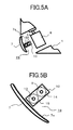
- Fig. 5A is an explanatory diagram showing the outlet 2 when the air conditioner shown in Fig. 1 is in a stop state
- Fig. 5B is a diagram showing the vertical blade driving means 19 shown in Fig. 5A
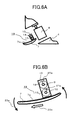
- Fig. 6A is an explanatory diagram showing the outlet 2 when the air conditioner shown in Fig. 1 blows the airflow from the outlet 2 in the horizontal direction
- Fig. 6B is a diagram showing the vertical blade driving means 19 shown in Fig. 6A .
- the vertical blade 7 is so tilted as to close the outlet 2.
- the air that has passed through the heat exchanger 6 reaches a setting temperature, and is then carried to the outlet 2.
- the slide motion motor is driven, the slide motion rotating shaft 9 rotates counterclockwise which is a direction indicated by an arrow 20a, and the first gear 14 that is fixed to the slide motion rotating shaft 9 rotates about the slide rotation rotating shaft 9 counterclockwise.
- the second gear 15 that is meshing with the first gear 14 rotates about the transmission rotating shaft 13 clockwise that is a direction indicated by an arrow 21a.
- the third gear 16 that is meshing with the fourth gear 18 rotates about the slide motion rotating shaft 9 counterclockwise, and the connector 10 that is fixed to the third gear 16 rotates about the slide motion rotating shaft 9 counterclockwise.
- the vertical blade 7 rotates so as to be directed in the horizontal direction, and the downstream end of the vertical blade 7 moves toward a downstream side which is a direction away from the slide motion rotating shaft 9. With the above-mentioned operation, even if the vertical blade 7 or the horizontal blade 8 is upsized, the upstream side end of the vertical blade 7 can be prevented from colliding with the horizontal blade 8.
- Fig. 7A is an explanatory diagram showing the outlet 2 when the air conditioner shown in Fig. 1 blows the airflow from the outlet 2 in the downward direction
- Fig. 7B is a diagram showing the vertical blade driving means 19 of Fig. 7A .
- the air conditioner When the air conditioner is operated by a user so as to blow the airflow in the downward direction from a state where the vertical blade 7 closes the outlet 2, the airflow occurs due to the rotation of the fan 5, and the air that has been sucked in from the inlet 1 passes through the heat exchanger 6, and is then carried to the outlet 2.
- the slide motion motor is driven, the slide motion rotating shaft 9 rotates clockwise which is a direction indicated by an arrow 20b, and the first gear 14 that is fixed to the slide motion rotating shaft 9 rotates about the slide rotation rotating shaft 9 clockwise.
- the second gear 15 that is meshing with the first gear 14 rotates about the transmission rotating shaft 13 counterclockwise that is a direction indicated by an arrow 21b.
- the rotation motion rotating shaft 17 rotates counterclockwise by the drive of the rotation motion motor, and the fourth gear 18 that is fixed to the rotation motion rotating shaft 17 rotates about the rotation motion rotating shaft 17 counterclockwise.
- the third gear 16 that is meshing with the fourth gear 18 rotates about the slide motion rotating shaft 9 clockwise, and the connector 10 that is fixed to the third gear 16 rotates about the slide motion rotating shaft 9 clockwise.
- the vertical blade 7 rotates so as to be directed in the downward direction, and the downstream end of the vertical blade 7 moves toward a downstream side which is a direction away from the slide motion rotating shaft 9. With the above-mentioned operation, even if the vertical blade 7 or the horizontal blade 8 is upsized, the upstream side end of the vertical blade 7 can be prevented from colliding with the horizontal blade 8.
- the upstream end of the vertical blade 7 can approach a ceiling surface of the outlet 2, a part of airflow which passes through the upper side of the vertical blade 7 can be prevented from flowing in the upward direction without being deflected, and the controllability of the airflow can be further improved.
- a relative position between the slide motion rotating shaft 9 and the vertical blade 7 is changed by the vertical blade driving means 19, and the vertical blade 7 rotates about the slide motion rotating shaft 9.
- the upstream end of the vertical blade 7 approaches the ceiling surface of the outlet 2, thereby preventing a part of the airflow that passes through the upper side of the vertical blade 7 from flowing in the upward direction without being deflected. This enables the controllability of the airflow to be improved.
- the vertical blade driving means 19 inverts the vertical blade 7 in the upward or downward direction, and also changes the relative position between the slide motion rotating shaft 9 and the vertical blade 7 in a direction along which the downstream end of the vertical blade 7 is apart from the slide motion rotating shaft 9.
- the vertical blade driving means 19 has the second gear 15 that comes in contact with the vertical blade 7 and rotates in conjunction with the slide motion rotating shaft 9.
- the second gear 15 rotates while the vertical blade 7 moves in one direction with respect to the slide motion rotating shaft 9.
- the turning force of the slide motion rotating shaft 9 can be transmitted to the vertical blade 7 with the simple configuration.
- the vertical blade 7 is formed with the convex portion 7a which is meshing with the second gear 15, the turning force of the second gear 15 can be transmitted to the vertical blade 7 with a simple configuration.
- This embodiment exemplifies the vertical blade driving means 19 having the slide motion rotating shaft 9 that is connected to the slide motion motor and the rotation motion rotating shaft 17 that is connected to the rotation motion motor.
- the present invention is not limited to this configuration.
- the vertical blade driving means 19 can be configured in such a manner that a fifth gear 24 is fixed to the slide motion rotating shaft 9, and a sixth gear 25 that is meshing with the fifth gear 24 is fixed to the rotation motion rotating shaft 17 to rotate the slide motion rotating shaft 9 at the same time when the rotation motion rotating shaft 17 rotates.
- the motor can be fitted to any one of the slide motion rotating shaft 9 and the rotation motion rotating shaft 17, thereby enabling the number of motors to be reduced.
- Fig. 9 is a diagram showing another example of the vertical blade driving means 19 of the air conditioner according to this embodiment.
- the support 10b extends horizontally in a direction away from the connector main body 10a, then is bent toward the vertical blade 7, further bent before the vertical blade 7, and again extends horizontally in the direction away from the connector main body 10a.
- the vertical blade 7 includes an L-shaped support receiving portion 26 having a leading end directed toward the connector main body 10a on a surface thereof that faces the connector main body 10a.
- the leading end of the support 10b is slidably disposed inside of the support receiving portion 26.
- the vertical blade 7 is slidably supported to the connector 10.
- the support 10b is so disposed as to extend from one surface of the vertical blade 7 to another surface thereof with the result that the support 10b can be simply formed.
- a position at which the connector 10 is fitted is not limited to the end of the side surface of the outlet 2 of the vertical blade 7, but can be freely provided.
- Fig. 10 is a diagram showing still another example of the vertical blade driving means 19 of the air conditioner according to this embodiment.
- a lower side of the support 10b is U-shaped in cross section.
- the vertical blade 7 has a concave portion 27 along which the leading end of the support 10b is slidable on a surface thereof which faces the side surface that bounds the outlet 2.
- the vertical blade 7 is slidably supported to the connector 10.
- the support 10b since the support 10b does not extend up to a surface of the vertical blade 7 at an opposite side of the connector main body 10a, the surface of the vertical blade 7 at an opposite side of the connector main body 10a can further approach the ceiling surface or the bottom surface of the outlet 2.
- Fig. 11 is a perspective view showing yet still another example of the vertical blade driving means 19 of the air conditioner according to this embodiment.
- a surface of the vertical blade 7 which faces the connector main body 10a is formed with concave portions 7b which are an engaged portion which can be meshing with the second gear 15.
- a plurality of concave portions 7b are continuously aligned in a direction orthogonal to the transmission rotating shaft 13.
- the concave portion 7b reduces collision with the airflow as compared with the convex portion 7a, dust contained in the airflow can be prevented from being attached to the concave portion 7b.
- the engaged portion is not limited to the concave portion 7b having a bottom, but can be a through-hole that penetrates the vertical blade 6.
- Fig. 12 is a perspective view showing a main portion of an air conditioner according to this embodiment.
- a first cylindrical portion 28 that is fixed to the slide motion rotating shaft 9 and rotates together with the slide motion rotating shaft 9 is disposed inside of the connector main body 10a.
- a second cylindrical portion 29 that is a rotating body which is fixed to the transmission rotating shaft 13, rotates together with the transmission rotating shaft 13, and comes in contact with the vertical blade 7 is disposed inside of the connector main body 10a.
- the first cylindrical portion 28 and the second cylindrical portion 29 have rubber which is a slip stopper member on their peripheries which come in contact with each other.
- the second cylindrical portion 29 also rotates in conjunction with the first cylindrical portion 28, and the vertical blade 7 moves in one direction with respect to the second cylindrical member 29.
- the slip stopper member is not limited to rubber, but can also be made of other materials.
- the vertical blade 7 may have rubber which is the slip stopper member in a region where the vertical blade 7 comes in contact with the periphery of the second cylindrical portion 29, and the slip stopper member may also be disposed on any one of the second cylindrical portion 29 and the vertical blade 7.
- the first cylindrical portion 28, the second cylindrical portion 29, and the vertical blade 7 are not formed with the convex portion or the concave portion which are meshing with each other, and come in contact with surfaces that do not slip on each other. For this reason, the attachment of dust onto the first cylindrical portion 28, the second cylindrical portion 29, and the vertical blade 7 can be reduced as compared with the air conditioner according to the first embodiment.
- the respective embodiments exemplify the vertical blade 7 that is formed with the engaged portion which is meshing with the second gear 15, and the vertical blade 7 that comes in contact with the second cylindrical portion 29.
- the present invention is not limited to this configuration, but the vertical blade 7 may have a member formed with the engaged portion which is meshing with the second gear 15, or the vertical blade 7 may have a member that comes in contact with the second cylindrical portion 29.
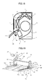
- Fig. 13 is a structural diagram showing an air conditioner according to this embodiment.
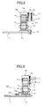
- Fig. 14 is a perspective view showing vertical blade driving means 34 shown in Fig. 13 .
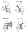
- Fig. 15A is a front view showing one end of the vertical blade driving means 34 shown in Fig. 15A
- Fig. 15B is a side view showing the vertical blade driving means 34 viewed along an arrow B in Fig. 15A
- Fig. 15C is a front view showing another end of the vertical blade driving means 34 in Fig. 14
- Fig. 15D is a side view showing the vertical blade driving means 34 viewed along an arrow D in Fig. 15C .
- a slide guide 30a is omitted in Fig. 15
- a slide motion motor 46 and a rotation motion motor 47 is omitted in Fig. 15D .
- the air conditioner according to this embodiment includes a vertical blade 30 having a circular arc configuration in cross section which is disposed at an outlet 2 and deflects the direction of the airflow which is blown out of the outlet 2 in the upward or downward direction, and a horizontal blade 31 which is disposed between a fan 5 and the vertical blade 30 and deflects the airflow within an air passage 3 in the right or left direction.
- a slide motion rotating shaft 32 that is a first rotating shaft which faces the vertical blade 30 and extends in the horizontal direction toward a side surface that bounds the outlet 2, and a rotation motion rotating shaft 33 that is a second rotating shaft which is in parallel to the slide motion rotating shaft 32 are rotatably supported to the outlet 2.
- Vertical blade driving means 34 that change a relative position between the vertical blade 30 and the slide motion rotating shaft 32, and rotate the vertical blade 30 about the slide motion rotating shaft 32 are disposed between the vertical blade 30 and the slide motion rotating shaft 32.
- the vertical blade driving means 34 include a connector 35 having one end rotatably supported to the slide motion rotating shaft 32 and another end supporting the vertical blade 30, a moving mechanism 36 that relatively moves the vertical blade 30 with respect to the connector 35, and a rotating mechanism 37 that rotates the connector 35 about the slide motion rotating shaft 32.
- the connectors 35 are disposed at both ends of the vertical blade 30, respectively, and the moving mechanisms 36 and the rotating mechanisms 37 are disposed on the respective connectors 35.
- Each of the moving mechanisms 36 includes a first rotating force transmission unit having a seventh gear 38 that is fixed to the slide motion rotating shaft 32 and rotates together with the slide motion rotating shaft 32, an eighth gear 39 that is rotatably supported to the connector 35 and meshing with the seventh gear 38, a ninth gear 40 that is rotatable and meshing with the eighth gear 39, and a transmission rotating shaft 41 which is rotatably supported by the connector 35, and whose one end is fixed to the ninth gear 40, and a tenth gear 42 that is a rotating body which is fixed to another end of the transmission rotating shaft 41.
- the seventh gear 38, the eighth gear 39, and the ninth gear 40 are aligned from the slide motion rotating shaft 32 toward the vertical blade 30 inside of the connector 35 having a cavity therein.
- Ring-shaped slide guides 30a that are flattened are fixed at both side surfaces that bound the outlet 2 on a surface of the vertical blade 30 which faces the slide motion rotating shaft 32.
- Each of the slide guides 30a extends in a direction orthogonal to the slide motion rotating shaft 32, and projections 30b which are triangular first contact portions are continuously formed on a bottom surface of the interior of the slide guide 30a in the longitudinal direction.
- the above-mentioned embodiment exemplifies the vertical blade 30 having the slide guide 30a on which the projections 30b are formed.
- the present invention is not limited to the above-mentioned configuration, and the vertical blade 30 may be directly formed with the projections.
- the rotating mechanism 37 includes an eleventh gear 43 that is a second contact portion which is fixed to the connector 35 about the slide motion rotating shaft 32, and a second rotating force transmission unit having a twelfth gear 44 that is rotatable and meshing with the eleventh gear 43, and a thirteenth gear 45 that is fixed to the rotating motion rotating shaft 33 and meshing with the twelfth gear 44.
- the eleventh gear 43, the twelfth gear 44, and the thirteenth gear 45 are aligned from the slide motion rotating shaft 32 toward the rotation motion rotating shaft 33.
- the eleventh gear 43 can be integrated with the connector 35.
- the projections 30b, the seventh gear 38, the eighth gear 39, the ninth gear 40, the tenth gear 42, the eleventh gear 43, the twelfth gear 44, and the thirteenth gear 45 are made of copper-based metal.
- the present invention is not limited to the above-mentioned configuration, so these gears can be made of other materials such as iron-based metal, polyacetal resin, and nylon resin.
- slide motion rotating shaft 32 One end of the slide motion rotating shaft 32 is connected with a slide motion motor 46 which is a first motor that rotates the slide motion rotating shaft 32, and one end of the rotation motion rotating shaft 33 is connected with a rotation motion motor 47 which is a second motor that rotates the rotation motion rotating shaft 33.
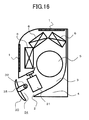
- Fig. 16 is a structural diagram showing a state in which the air conditioner shown in Fig. 13 is in a stop state.
- Fig. 17 is a structural diagram showing a state where the air conditioner shown in Fig. 13 blows the airflow out of the outlet 2 in the horizontal direction.
- Fig. 18 is a structural diagram showing a state where the air conditioner shown in Fig. 13 blows the airflow out of the outlet 2 in the downward direction.
- the vertical blade 30 is so tilted as to close the outlet 2.
- the rotation operation motor 47 is driven to rotate the rotation operation rotating shaft 33.
- the rotating force of the rotation operation rotating shaft 33 is transmitted to the eleventh gear 43 through the thirteenth gear 45 and the twelfth gear 44, and the connector 35 rotates about the slide motion rotating shaft 32 in such a direction that the concave portion of the vertical blade 30 is directed downwards in conjunction with the eleventh gear 43.
- the vertical blade 30 rotates at a large angle, the vertical blade 30 can approach the ceiling surface of the outlet 2. Accordingly, the airflow that has passed through the upper side of the vertical blade 30 is prevented from flowing in the upward direction. As a result, it is possible to improve the controllability of the airflow.
- the slide motion motor 46 is driven to rotate the slide motion rotating shaft 32, and the rotating force of the slide motion rotating shaft 32 is transmitted to the tenth gear 42 through the seventh gear 38, the eighth gear 39, the ninth gear 40, and the transmission rotating shaft 41.
- the vertical blade 30 Since the tenth gear 42 rotates while meshing with the projections 30b, the vertical blade 30 relatively moves in a direction along which the downstream end is apart from the slide motion rotating shaft 32 with respect to the connector 35.
- the vertical blade 30 can be prevented from colliding with the horizontal blade 31 or the ceiling surface of the outlet 2.
- the rotation operation motor 47 is driven in an opposite direction to that at the time of the heater operation to rotate the rotation operation rotating shaft 33.
- the rotating force of the rotation operation rotating shaft 33 is transmitted to the eleventh gear 43 through the thirteenth gear 45 and the twelfth gear 44, and the connector 35 rotates about the slide motion rotating shaft 32 in such a direction that the concave portion of the vertical blade 30 is directed upwards in conjunction with the eleventh gear 43.
- the vertical blade 30 rotates at a large angle, the vertical blade 30 can approach the bottom surface of the outlet 2. Accordingly, the airflow that has passed through the lower side of the vertical blade 30 is prevented from flowing in the downward direction. As a result, it is possible to improve the controllability of the airflow.
- the slide motion motor 46 is driven in an opposite direction to that at the time of the heater operation to rotate the slide motion rotating shaft 32.
- the rotating force of the slide motion rotating shaft 32 is transmitted to the tenth gear 42 through the seventh gear 38, the eighth gear 39, the ninth gear 40, and the transmission rotating shaft 41.
- the vertical blade 30 Since the tenth gear 42 rotates while meshing with the projections 30b, the vertical blade 30 relatively moves in a direction in which the downstream end is apart from the slide motion rotating shaft 32 with respect to the connector 35.
- the vertical blade 30 can be prevented from colliding with the horizontal blade 31 or the ceiling surface of the outlet 2.
- the relative position between the slide motion rotating shaft 32 and the vertical blade 30 is changed by the vertical blade driving means 34, and the vertical blade 30 rotates about the slide motion rotating shaft 32.
- the upstream end of the vertical blade 30 is made to approach the ceiling surface of the outlet 2 to prevent a part of the airflow that passes through the upper side of the vertical blade 30 from flowing in the upward direction without being deflected.
- the controllability of the airflow can be improved.
- the slide motion motor 46 and the vertical blade 30 can be disposed apart from each other by the first rotating force transmitting means, and the rotation motion motor 47 and the vertical blade 30 can be disposed apart from each other by the second rotating force transmitting means. For this reason, a pressure loss of the airflow within the air passage 3 due to the slide motion motor 46 or the rotation motion motor 47 can be reduced, and dew condensation that is produced by the generation of a turbulent flow can be prevented.
- the slide motion rotating shaft 32 is rotated by the drive of the slide motion motor 46, and the rotation motion rotating shaft 33 is rotated by the drive of the rotation motion motor 47.
- the vertical blade 30 can be rotated in order that the vertical blade 30 does not collide with the outlet 2 or the horizontal blade 31.
- the slide motion motor 46 is driven, thereby making it possible to protrude the vertical blade 30 to the downstream side, or retract the vertical blade 30 to the upstream side.
- the flow passage of the outlet 2 is narrowed to reduce the air flow, thereby making it possible to accelerate the flow rate of the airflow to extend the arrival distance of the airflow, and to further improve the controllability of the airflow.
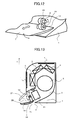
- Fig. 19 is a perspective view showing another example of the vertical blade driving means 34 in the air conditioner according to this embodiment.
- Fig. 20A is a front view showing one end of the vertical blade driving means 34 shown in Fig. 19 .
- Fig. 20B is a side view showing the vertical blade driving means 34 viewed along the arrow B in Fig. 20A.
- Fig. 20C is a front view showing another end of the vertical blade driving means 34 shown in Fig. 19 .
- Fig. 20D is a side view showing the vertical blade driving means 34 viewed along an arrow D in Fig. 20C .
- the slide guide 30a is omitted in Fig. 20
- the rotation motion motor 47 is omitted in Fig. 20B
- the slide motion motor 46 is omitted in Fig. 8D.
- the slide motion motor 46 is disposed at one side surface of the outlet 2, and the rotation motion motor 47 is disposed at another side surface of the outlet 2.
- the rotation motion rotating shaft 33 extends between the rotation motion motor 47 and one of the connectors 35 which is closer to the rotation motion motor 47, and the rotating mechanism 37 is disposed on the one connector 35.
- the connector 35, the rotating mechanism 37, and the vertical blade 30 are made of a material having mechanical rigidity to the degree that the vertical blade 30 and another connector 35 can rotate about the slide motion rotating shaft 32 when one connector 35 rotates about the slide motion rotating shaft 32.
- the slide motion motor 46 and the rotation motion motor 47 are disposed apart from each other, the degree of freedom of the sizes of the slide motion motor 46 and the rotation motion motor 47 is improved.
- the rotation motion rotating shaft 33 extends between the rotation motion motor 47 and one of the connectors 35 which is closer to the rotation motion motor 47, and is not disposed between the respective connectors 35. As a result, the airflow that flows along the vertical blade 30 can be prevented from being obstructed by the rotation motion rotating shaft 33.
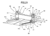
- Fig. 21 is a perspective view showing vertical blade driving means 34 of an air conditioner according to this embodiment.
- Fig. 22A is a front view showing one end of the vertical blade driving means 34 of Fig. 21 .
- Fig. 22B is a side view showing the vertical blade driving means 34 viewed along the arrow B of Fig. 22A.
- Fig. 22C is a front view showing another end of the vertical blade driving means 34 of Fig. 21 .
- Fig. 22D is a side view showing the vertical blade driving means 34 viewed along an arrow D of Fig. 22C .
- the slide guide 30a is omitted in Figs. 22
- the motor 50 is omitted in Fig. 22D .
- a third rotating force transmission unit having a fourteenth gear 48 that is fixed to the slide motion rotating shaft 32 and rotates together with the slide motion rotating shaft 32, and a fifteenth gear 49 that is fixed to the rotation motion rotating shaft 33, rotates together with the rotation motion rotating shaft 33, and is meshing with the fourteenth gear 48 is disposed in each of the connectors 35.
- the slide motion rotating shaft 32 extends between the respective connectors 35, and the motor 50 is fitted to one end of the slide motion rotating shaft 32. No motor is fitted to the rotation motion rotating shaft 33.
- This embodiment exemplifies the air conditioner in which the rotation motion rotating shaft 33 is disposed in each of the connectors 35.
- an air conditioner having one rotation motion rotating shaft 33 that extends between the respective connectors 35.
- the air conditioner in which the motor is fitted to the rotation motion rotating shaft 33, and no motor is fitted to the slide motion rotating shaft 32. Even in this case, the rotating force of the rotation motion rotating shaft 33 can be transmitted to the slide motion rotating shaft 32 by the aid of the third rotating force transmission unit.
- the motor 50 is driven to rotate the slide motion rotating shaft 32, and the rotating force of the slide motion rotating shaft 32 is transmitted to the tenth gear 42 as in the air conditioner according to the third embodiment.
- the vertical blade 30 relatively moves in such a direction that the downstream end is apart from the slide motion rotating shaft 32 with respect to the connector 35.
- the vertical blade 30 rotates in a direction along which the concave portion is directed downwardly.
- the motor 50 When the air conditioner is so operated as to conduct cooling operation, the motor 50 is driven in an opposite direction to that at the time of the heating operation, and the vertical blade 30 relatively moves in a direction in which the downstream end is apart from the slide motion rotating shaft 32 with respect to the connector 35. Also, the vertical blade 30 rotates in a direction in which the concave portion is directed upwardly.
- the vertical blade 30 can rotate so as not to collide with the outlet 2 or the horizontal blade 31.
- the number of motors can be reduced as compared with the air conditioner of the third embodiment, and the air conditioner can be downsized.
- the third embodiment and the fourth embodiment exemplify the moving mechanism 36 in which the rotating force of the slide motion rotating shaft 32 is transmitted to the vertical blade 30 through the projections 30b, the seventh gear 38, the eighth gear 39, the ninth gear 40, the transmission rotating shaft 41, and the tenth gear 42 to move the vertical blade 30.
- the present invention is not limited to the above-mentioned configuration.
- a moving mechanism 36 in which the rotating force of the slide motion rotating shaft 32 is transmitted to the vertical blade 30 by the aid of a frictional force of, for example, a rubber roller, a metal roller, or a resin roller to move the vertical blade 30.
- a moving mechanism 36 in which the rotating force of the slide motion rotating shaft 32 is transmitted to the vertical blade 30 by the aid of a belt drive of a geared belt, a V-belt, or the like to move the vertical blade 30.
- the third embodiment and the fourth embodiment exemplify the rotating mechanism 37 in which the rotating force of the rotation motion rotating shaft 33 is transmitted to the connector 35 through the eleventh gear 43, the twelfth gear 44, and the thirteenth gear 45 to rotate the connector 35.
- the present invention is not limited to the above-mentioned configuration.
- a rotating mechanism 37 in which the rotating force of the rotation motion rotating shaft 33 is transmitted to the connector 35 by the aid of a frictional force of, for example, a rubber roller, a metal roller, or a resin roller to rotate the connector 35.
- a rotating mechanism 37 in which the rotating force of the rotation motion rotating shaft 33 is transmitted to the connector 35 by the aid of a belt drive of a geared belt, a V-belt, or the like to rotate the connector 35.
- the third embodiment and the fourth embodiment exemplify the air conditioner having the seventh gear 38, the eighth gear 39, the ninth gear 40, the tenth gear 42, the eleventh gear 43, the twelfth gear 44, the thirteenth gear 45, the fourteenth gear 48, and the fifteenth gear 49.
- the number of gears is not limited to the above-mentioned example.
- the fourth embodiment exemplifies the third rotating force transmission unit having the fourteenth gear 48 and the fifteenth gear 49 that transmit the rotating force of the slide motion rotating shaft 32 to the rotation motion rotating shaft 33 between the slide motion rotating shaft 32 and the rotation motion rotating shaft 33.
- the present invention is not limited to the above-mentioned example.
- a third rotating force transmission unit in which the rotating force of the slide motion rotating shaft 32 is transmitted to the rotation motion rotating shaft 33 by the aid of a frictional force of, for example, a rubber roller, a metal roller, or a resin roller.
- a third rotating force transmission unit in which the rotating force of the slide motion rotating shaft 32 is transmitted to the rotation motion rotating shaft 33 by the aid of a belt drive of a geared belt, a V-belt, or the like.
Landscapes
- Engineering & Computer Science (AREA)
- Chemical & Material Sciences (AREA)
- Combustion & Propulsion (AREA)
- Mechanical Engineering (AREA)
- General Engineering & Computer Science (AREA)
- Air-Flow Control Members (AREA)
Applications Claiming Priority (2)
| Application Number | Priority Date | Filing Date | Title |
|---|---|---|---|
| JP2007221094A JP4426609B2 (ja) | 2007-08-28 | 2007-08-28 | 空気調和機 |
| JP2007221088A JP4430697B2 (ja) | 2007-08-28 | 2007-08-28 | 空気調和機 |
Publications (2)
| Publication Number | Publication Date |
|---|---|
| EP2031320A1 true EP2031320A1 (fr) | 2009-03-04 |
| EP2031320B1 EP2031320B1 (fr) | 2012-10-10 |
Family
ID=40028941
Family Applications (1)
| Application Number | Title | Priority Date | Filing Date |
|---|---|---|---|
| EP08162940A Not-in-force EP2031320B1 (fr) | 2007-08-28 | 2008-08-26 | Climatiseur |
Country Status (2)
| Country | Link |
|---|---|
| EP (1) | EP2031320B1 (fr) |
| ES (1) | ES2392366T3 (fr) |
Cited By (4)
| Publication number | Priority date | Publication date | Assignee | Title |
|---|---|---|---|---|
| EP2498019A4 (fr) * | 2009-11-05 | 2013-11-13 | Daikin Ind Ltd | Unité d'intérieur pour climatiseur |
| EP2848872A1 (fr) * | 2013-09-17 | 2015-03-18 | Samsung Electronics Co., Ltd | Climatiseur |
| EP2746691A4 (fr) * | 2011-08-16 | 2015-04-08 | Gree Electric Appliances Inc | Climatiseur intérieur |
| CN112856793A (zh) * | 2021-02-01 | 2021-05-28 | 珠海格力电器股份有限公司 | 扫风结构及其控制方法、空调器 |
Citations (4)
| Publication number | Priority date | Publication date | Assignee | Title |
|---|---|---|---|---|
| FR2554216A1 (fr) * | 1983-10-26 | 1985-05-03 | Hitachi Ltd | Conditionneur d'air |
| JPH03158647A (ja) | 1989-11-16 | 1991-07-08 | Matsushita Electric Ind Co Ltd | 空気調和機の風向偏向装置 |
| EP0657701A2 (fr) * | 1993-12-10 | 1995-06-14 | Fujitsu General Limited | Dispositif de climatisation |
| EP1271065A2 (fr) * | 2001-06-19 | 2003-01-02 | Lg Electronics Inc. | Dispositif de conditionnement d'air |
-
2008
- 2008-08-26 ES ES08162940T patent/ES2392366T3/es active Active
- 2008-08-26 EP EP08162940A patent/EP2031320B1/fr not_active Not-in-force
Patent Citations (4)
| Publication number | Priority date | Publication date | Assignee | Title |
|---|---|---|---|---|
| FR2554216A1 (fr) * | 1983-10-26 | 1985-05-03 | Hitachi Ltd | Conditionneur d'air |
| JPH03158647A (ja) | 1989-11-16 | 1991-07-08 | Matsushita Electric Ind Co Ltd | 空気調和機の風向偏向装置 |
| EP0657701A2 (fr) * | 1993-12-10 | 1995-06-14 | Fujitsu General Limited | Dispositif de climatisation |
| EP1271065A2 (fr) * | 2001-06-19 | 2003-01-02 | Lg Electronics Inc. | Dispositif de conditionnement d'air |
Cited By (7)
| Publication number | Priority date | Publication date | Assignee | Title |
|---|---|---|---|---|
| EP2498019A4 (fr) * | 2009-11-05 | 2013-11-13 | Daikin Ind Ltd | Unité d'intérieur pour climatiseur |
| US9897335B2 (en) | 2009-11-05 | 2018-02-20 | Daikin Industries, Ltd. | Indoor unit of air conditioning apparatus |
| EP2746691A4 (fr) * | 2011-08-16 | 2015-04-08 | Gree Electric Appliances Inc | Climatiseur intérieur |
| US9885488B2 (en) | 2011-08-16 | 2018-02-06 | Gree Electric Appliances, Inc. Of Zhuhai | Indoor unit of air conditioner |
| EP2848872A1 (fr) * | 2013-09-17 | 2015-03-18 | Samsung Electronics Co., Ltd | Climatiseur |
| US10393422B2 (en) | 2013-09-17 | 2019-08-27 | Samsung Electronics Co., Ltd. | Air conditioner |
| CN112856793A (zh) * | 2021-02-01 | 2021-05-28 | 珠海格力电器股份有限公司 | 扫风结构及其控制方法、空调器 |
Also Published As
| Publication number | Publication date |
|---|---|
| ES2392366T3 (es) | 2012-12-10 |
| EP2031320B1 (fr) | 2012-10-10 |
Similar Documents
| Publication | Publication Date | Title |
|---|---|---|
| CN101377332B (zh) | 空调机 | |
| CN102162674B (zh) | 滑动门装置 | |
| JP4426609B2 (ja) | 空気調和機 | |
| US8230693B2 (en) | Interior panel of air conditioner and air conditioner | |
| AU2013205424B2 (en) | Air conditioner | |
| EP2031320B1 (fr) | Climatiseur | |
| KR20040007323A (ko) | 공기조화기 | |
| JP5502409B2 (ja) | 車両用空調装置 | |
| EP2650152A1 (fr) | Dispositif de climatisation pour véhicule | |
| WO2013054594A1 (fr) | Appareil de climatisation pour véhicule à passagers | |
| JP5954231B2 (ja) | 車両用空調装置 | |
| JP6648988B2 (ja) | 空気調和機 | |
| JP3792032B2 (ja) | 空気調和機の風向調節装置 | |
| JP2018079719A (ja) | 車両用空調装置 | |
| EP2361796A1 (fr) | Unité de climatisation pour véhicule | |
| JP4810341B2 (ja) | 空気調和機 | |
| JP2008025880A (ja) | 空気調和機 | |
| EP4056917A1 (fr) | Structure d'écoulement d'air indirect pour climatiseur et climatiseur la comprenant | |
| AU2018271456B2 (en) | Indoor unit for air conditioner | |
| JP4267993B2 (ja) | 車両用空調ユニットの組立構造およびこれに用いるリンク機構 | |
| JP2008138957A (ja) | 風向変更装置及びこれを備えた空気調節装置 | |
| CN106457963A (zh) | 车辆用空调装置 | |
| JP4252408B2 (ja) | 車両用空調ユニット | |
| JP6773592B2 (ja) | 車両用空調装置 | |
| JP2017149363A (ja) | 車両用空調装置 |
Legal Events
| Date | Code | Title | Description |
|---|---|---|---|
| PUAI | Public reference made under article 153(3) epc to a published international application that has entered the european phase |
Free format text: ORIGINAL CODE: 0009012 |
|
| AK | Designated contracting states |
Kind code of ref document: A1 Designated state(s): AT BE BG CH CY CZ DE DK EE ES FI FR GB GR HR HU IE IS IT LI LT LU LV MC MT NL NO PL PT RO SE SI SK TR |
|
| AX | Request for extension of the european patent |
Extension state: AL BA MK RS |
|
| 17P | Request for examination filed |
Effective date: 20090203 |
|
| AKX | Designation fees paid |
Designated state(s): DE ES FR IT |
|
| GRAP | Despatch of communication of intention to grant a patent |
Free format text: ORIGINAL CODE: EPIDOSNIGR1 |
|
| GRAS | Grant fee paid |
Free format text: ORIGINAL CODE: EPIDOSNIGR3 |
|
| GRAA | (expected) grant |
Free format text: ORIGINAL CODE: 0009210 |
|
| AK | Designated contracting states |
Kind code of ref document: B1 Designated state(s): DE ES FR IT |
|
| REG | Reference to a national code |
Ref country code: DE Ref legal event code: R096 Ref document number: 602008019250 Country of ref document: DE Effective date: 20121206 |
|
| REG | Reference to a national code |
Ref country code: ES Ref legal event code: FG2A Ref document number: 2392366 Country of ref document: ES Kind code of ref document: T3 Effective date: 20121210 |
|
| PLBE | No opposition filed within time limit |
Free format text: ORIGINAL CODE: 0009261 |
|
| STAA | Information on the status of an ep patent application or granted ep patent |
Free format text: STATUS: NO OPPOSITION FILED WITHIN TIME LIMIT |
|
| 26N | No opposition filed |
Effective date: 20130711 |
|
| REG | Reference to a national code |
Ref country code: DE Ref legal event code: R097 Ref document number: 602008019250 Country of ref document: DE Effective date: 20130711 |
|
| REG | Reference to a national code |
Ref country code: DE Ref legal event code: R084 Ref document number: 602008019250 Country of ref document: DE |
|
| PGFP | Annual fee paid to national office [announced via postgrant information from national office to epo] |
Ref country code: FR Payment date: 20140808 Year of fee payment: 7 |
|
| REG | Reference to a national code |
Ref country code: ES Ref legal event code: GC2A Effective date: 20141209 |
|
| REG | Reference to a national code |
Ref country code: DE Ref legal event code: R084 Ref document number: 602008019250 Country of ref document: DE Effective date: 20141107 |
|
| REG | Reference to a national code |
Ref country code: FR Ref legal event code: ST Effective date: 20160429 |
|
| PG25 | Lapsed in a contracting state [announced via postgrant information from national office to epo] |
Ref country code: FR Free format text: LAPSE BECAUSE OF NON-PAYMENT OF DUE FEES Effective date: 20150831 |
|
| PGFP | Annual fee paid to national office [announced via postgrant information from national office to epo] |
Ref country code: DE Payment date: 20190813 Year of fee payment: 12 Ref country code: IT Payment date: 20190821 Year of fee payment: 12 Ref country code: ES Payment date: 20190903 Year of fee payment: 12 |
|
| REG | Reference to a national code |
Ref country code: DE Ref legal event code: R119 Ref document number: 602008019250 Country of ref document: DE |
|
| PG25 | Lapsed in a contracting state [announced via postgrant information from national office to epo] |
Ref country code: DE Free format text: LAPSE BECAUSE OF NON-PAYMENT OF DUE FEES Effective date: 20210302 Ref country code: IT Free format text: LAPSE BECAUSE OF NON-PAYMENT OF DUE FEES Effective date: 20200826 |
|
| REG | Reference to a national code |
Ref country code: ES Ref legal event code: FD2A Effective date: 20220110 |
|
| PG25 | Lapsed in a contracting state [announced via postgrant information from national office to epo] |
Ref country code: ES Free format text: LAPSE BECAUSE OF NON-PAYMENT OF DUE FEES Effective date: 20200827 |