EP2031325A2 - Accumulateur, en particulier pour une installation de climatisation, doté d'un collecteur d'impuretés - Google Patents
Accumulateur, en particulier pour une installation de climatisation, doté d'un collecteur d'impuretés Download PDFInfo
- Publication number
- EP2031325A2 EP2031325A2 EP20080011669 EP08011669A EP2031325A2 EP 2031325 A2 EP2031325 A2 EP 2031325A2 EP 20080011669 EP20080011669 EP 20080011669 EP 08011669 A EP08011669 A EP 08011669A EP 2031325 A2 EP2031325 A2 EP 2031325A2
- Authority
- EP
- European Patent Office
- Prior art keywords
- housing
- accumulator
- region
- trough
- accumulator according
- Prior art date
- Legal status (The legal status is an assumption and is not a legal conclusion. Google has not performed a legal analysis and makes no representation as to the accuracy of the status listed.)
- Withdrawn
Links
- 238000004378 air conditioning Methods 0.000 title claims abstract description 9
- 239000002245 particle Substances 0.000 claims abstract description 10
- 230000007704 transition Effects 0.000 claims abstract description 4
- 239000003507 refrigerant Substances 0.000 claims description 24
- 230000002093 peripheral effect Effects 0.000 claims description 12
- 239000000463 material Substances 0.000 claims description 9
- XAGFODPZIPBFFR-UHFFFAOYSA-N aluminium Chemical compound [Al] XAGFODPZIPBFFR-UHFFFAOYSA-N 0.000 claims description 4
- 229910052782 aluminium Inorganic materials 0.000 claims description 4
- 238000001125 extrusion Methods 0.000 claims description 4
- 239000002826 coolant Substances 0.000 abstract 2
- 239000007792 gaseous phase Substances 0.000 description 4
- 239000002274 desiccant Substances 0.000 description 3
- 239000007791 liquid phase Substances 0.000 description 3
- 238000004519 manufacturing process Methods 0.000 description 3
- 230000001914 calming effect Effects 0.000 description 2
- 239000011362 coarse particle Substances 0.000 description 2
- 239000012535 impurity Substances 0.000 description 2
- 239000007788 liquid Substances 0.000 description 2
- 238000005461 lubrication Methods 0.000 description 2
- 230000035508 accumulation Effects 0.000 description 1
- 238000009825 accumulation Methods 0.000 description 1
- 238000010276 construction Methods 0.000 description 1
- 230000001419 dependent effect Effects 0.000 description 1
- 230000008021 deposition Effects 0.000 description 1
- 239000004744 fabric Substances 0.000 description 1
- 230000005484 gravity Effects 0.000 description 1
- 230000000977 initiatory effect Effects 0.000 description 1
- 238000000034 method Methods 0.000 description 1
- 230000000717 retained effect Effects 0.000 description 1
- 238000000926 separation method Methods 0.000 description 1
- 239000002689 soil Substances 0.000 description 1
- 238000011144 upstream manufacturing Methods 0.000 description 1
- 239000002759 woven fabric Substances 0.000 description 1
Images


Classifications
-
- F—MECHANICAL ENGINEERING; LIGHTING; HEATING; WEAPONS; BLASTING
- F25—REFRIGERATION OR COOLING; COMBINED HEATING AND REFRIGERATION SYSTEMS; HEAT PUMP SYSTEMS; MANUFACTURE OR STORAGE OF ICE; LIQUEFACTION SOLIDIFICATION OF GASES
- F25B—REFRIGERATION MACHINES, PLANTS OR SYSTEMS; COMBINED HEATING AND REFRIGERATION SYSTEMS; HEAT PUMP SYSTEMS
- F25B43/00—Arrangements for separating or purifying gases or liquids; Arrangements for vaporising the residuum of liquid refrigerant, e.g. by heat
- F25B43/006—Accumulators
-
- F—MECHANICAL ENGINEERING; LIGHTING; HEATING; WEAPONS; BLASTING
- F25—REFRIGERATION OR COOLING; COMBINED HEATING AND REFRIGERATION SYSTEMS; HEAT PUMP SYSTEMS; MANUFACTURE OR STORAGE OF ICE; LIQUEFACTION SOLIDIFICATION OF GASES
- F25B—REFRIGERATION MACHINES, PLANTS OR SYSTEMS; COMBINED HEATING AND REFRIGERATION SYSTEMS; HEAT PUMP SYSTEMS
- F25B2500/00—Problems to be solved
- F25B2500/01—Geometry problems, e.g. for reducing size
-
- F—MECHANICAL ENGINEERING; LIGHTING; HEATING; WEAPONS; BLASTING
- F25—REFRIGERATION OR COOLING; COMBINED HEATING AND REFRIGERATION SYSTEMS; HEAT PUMP SYSTEMS; MANUFACTURE OR STORAGE OF ICE; LIQUEFACTION SOLIDIFICATION OF GASES
- F25B—REFRIGERATION MACHINES, PLANTS OR SYSTEMS; COMBINED HEATING AND REFRIGERATION SYSTEMS; HEAT PUMP SYSTEMS
- F25B43/00—Arrangements for separating or purifying gases or liquids; Arrangements for vaporising the residuum of liquid refrigerant, e.g. by heat
- F25B43/02—Arrangements for separating or purifying gases or liquids; Arrangements for vaporising the residuum of liquid refrigerant, e.g. by heat for separating lubricants from the refrigerant
Definitions
- the invention relates to an accumulator, in particular for an air conditioner, with strainer according to the preamble of claim 1.
- This accumulator has a housing, a flow path for a refrigerant with an inlet pipe, which is the input side connected to a refrigerant supply line and the output side opens to the housing interior, a U-shaped curved outlet pipe, the input side to the housing interior open and output side with a refrigerant drain line is connectable, a housed inside the housing desiccant.
- the flow path communicates via a passage opening with a lower region of the housing interior.
- a sieve which is supported by a portafilter.
- the portafilter has a positioning element for aligning the screen with respect to the passage opening and a holding device, so that the portafilter for mounting on the outlet tube can be plugged onto the outlet tube from outside.
- the screen is designed as a flat screen fabric, and the portafilter has support bars for supporting the screen surface.
- the housing is cylindrical, wherein it has a cylindrical peripheral wall and a slightly outwardly turned bottom wall, which is flat in the region of the portafilter. At the top, a lid with an inlet and an outlet is provided. The attachment of such a battery is carried out by means of a holder.
- Another, generic accumulator is from the WO 98/10854 A1 known.
- the housing is formed with a cylindrical peripheral wall and an outwardly turned bottom.
- no separately formed lid is provided, but also the upper portion formed everted outwards, wherein openings are provided for the supply and discharge.
- a passage opening in the U-tube for the oil is provided at the lowest point of the U-tube, with a sieve being attached to the U-tube by means of a holding device in front of it so that a certain distance remains between the base and the sieve. The attachment of such a battery is carried out by means of a holder.
- the US 4,651,540 A discloses an accumulator having a multi-part construction, consisting of a cover, a cylindrical peripheral wall and a separately formed therefrom, inverted bottom, wherein in the lowermost region an outwardly projecting threaded pin for mounting the accumulator is provided.
- a comparable housing structure of a rechargeable battery is also known from the US 5,076,071 A known.
- the US 5,660,058 A discloses an accumulator with a U-tube, at the bottom of an opening with upstream filter is described.
- the accumulator has a cylindrical, approximately centrally divided thermoformed housing with a constant wall thickness, wherein in the lowermost region - offset by a kind of step - a trough-like depression is formed into which the filter protrudes, the passage area completely within the tub is located close to the ground.
- the arrangement of the opening very far down ensures that sufficient oil that collects in the lowest part of the accumulator, is taken along by the U-tube flowing gaseous refrigerant, so that a sufficient lubrication, in particular of the compressor can be ensured.
- dirt accumulates in the bottom area of the accumulator, which can lead to problems.
- an accumulator in particular for an air conditioner, comprising a housing with a lid, wherein in the bottom region of the housing, a trough for collecting the oil contained in the refrigerant and dirt particles is formed, which has a cross section which is smaller than the cross section in is arranged above the region of the housing of the accumulator, wherein the transition to the trough is formed like a step, a flow path for a refrigerant with an inlet, which is the input side with a refrigerant supply line connectable and the output side opens to the housing interior, a U-shaped curved outlet pipe, which is on the input side to the housing interior open and output side connectable to a refrigerant discharge line, wherein the flow path is connected via a passage opening with a lower portion of the housing interior, and in front of the passage opening an oil filter is arranged, wherein the oil filter is arranged at least with a substantial portion of its passage area above the trough.
- the well formed in the bottom portion of the housing serves, in particular, to collect the oil which separates from the (liquid) refrigerant and to absorb dirt, among other things from the dirt retained by the oil filter.
- the oil filter is arranged with a substantial portion of its passage area relatively high above the lowest surface of the accumulator, a sufficient space for receiving dirt particles is present. Complete clogging of the filter by the soil collecting dirt can be safely avoided, so that always enough oil passes through the passage surface to the through hole of the U-tube and the lubrication function is ensured.
- the passage opening (or possibly also passage openings) in front of which the oil filter is arranged is preferably arranged in the lower, curved region of the U-shaped outlet pipe in the uppermost region or above the trough, so that a distance of approximately between the lower surface of the housing the tub depth or more than the tub depth is formed. This provides a sufficiently large collecting space for dirt particles.
- the filter surrounds the U-tube, for which purpose it is preferably clipped to the U-tube.
- the passage area for the oil ie the area in which the filter material is provided and oil can flow, preferably extends over a substantial area of the circumference of the U-tube, ie over preferably at least 50%, in particular at least 60%, 70% or more preferably at least 80% of the circumference.
- the filter is formed like a ring.
- the housing is preferably formed integrally by means of extrusion.
- extrusion i. a pressure forming method according to DIN 8583
- the available space can be optimized, especially in the bottom area of the accumulator, the space can be optimally designed and thus used optimally.
- the housing of the accumulator is preferably made of aluminum, in particular aluminum of the groups Al 3xxx, Al 5xxx or Al 6xxx. These materials can be well formed by extrusion molding and are also suitable as a housing for a rechargeable battery.
- the housing is provided on the outside in the bottom region with a positioning structure that differs at least partially from the cylindrical shape.
- the positioning structure is preferably formed by a three, four, five, six, seven or octagon, more preferably by a hexagon or octagon.
- the provision of a positioning structure which differs at least in a region from the cylindrical shape makes possible a simple, exact positioning, also with regard to the orientation in the circumferential direction.
- the accumulator can also be handled easier when torques, for example.
- the tightening torque during assembly of the accumulator occur because, for example, a hexagon, can serve as a means for capturing torque forces.
- the accumulator can be installed without a holder provided on the circumference with a corresponding configuration of a recording. A simple inclusion in a tree module for the positioning structure is sufficient.
- the trough in the bottom region of the housing preferably extends at least partially into a positioning structure formed on the outside, ie a partial region of the positioning structure is hollow on the inside, so that material and weight can be saved. Also can be saved by the optimized use of space height.
- the minimum material thickness in the central longitudinal axis of the housing preferably corresponds at most to twice the wall thickness in the peripheral wall region of the housing, more preferably at most one and a half times the wall thickness, and most preferably at most the simple wall thickness in the peripheral wall region of the housing.
- an oil filter is preferably provided in front of the passage opening and at least one coarse filter for large dirt particles above the oil filter. So coarse impurities can be removed before the actual oil filter and collected in an area above the bottom area. This prevents or reduces at least a significant change in the level of the stored oil volume by accumulating dirt in the course of operation of the accumulator.
- the coarse filter is preferably formed by a sheet provided with a plurality of through holes, however, for example, a coarse mesh or woven fabric or other suitable means for coarse particle deposition is also suitable.
- the coarse filter is used in addition to the separation of coarse particles and the calming of the oil and possibly existing liquid refrigerant below the coarse filter, so that even finer dirt particles settle on the floor.
- particles are deposited which are finer than the mesh size of the oil filter, so that the compressor is additionally at least partially protected against the finest particles.
- Such an accumulator is preferably arranged in a refrigerant circuit, in particular an automotive air conditioning system.
- An accumulator 1 as used for example for motor vehicle air conditioning systems, has a housing 2 with a separately formed, fixed from above on the housing 2 lid 3.
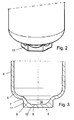
- the housing 2 has a substantially cylindrical peripheral wall 4 and a bottom region 5, the structure of which will be discussed in more detail below.
- the bottom region 5 begins substantially without transition from the peripheral wall 4 with a first curvature 6, in which region the wall thickness substantially corresponds to the wall thickness of the peripheral wall 4, ie is constant.
- a second curvature 7 follows in the opposite direction.
- the curvature 7 merges in a radius 8 into a surface 9 extending radially to the central longitudinal axis of the housing 2, the region formed by the curvature 7, the radius 8 and the surface 9 forming a trough 10 in the bottom region 5 form.
- the curvature 7 merges into a hexagon 11, which is parallel to the central longitudinal axis of the housing 2 extending surfaces and in the radial direction to the central longitudinal axis of the housing 2 extending end surface 12 has.
- the minimum material thickness which is arranged in the region between the surface 9 and the end surface 12, about the wall thickness of the peripheral wall 4. Due to the hexagon 11 and the trough 10 material accumulations are substantially only in the region of the edge outer sides of the hexagon eleventh intended.
- the hexagon 11 here forms a positioning structure, with the aid of which the accumulator 1 can be used here in a front module made of plastic with a hexagon socket as a receptacle, so that the accumulator 1 is mounted rotatably and torque-safe, and provided on the cover terminals 20 are secured.
- the accumulator 1 has said connections 20 and 27 provided on its cover, which are connected to the supply and discharge line (not shown) for the refrigerant.
- the continuation of the supply line ends in the uppermost region of the accumulator 1.
- the discharge is connected to the U-tube 21 with different lengths of legs, via which gaseous refrigerant is sucked out of the interior.
- a desiccant is arranged in a receptacle 22 in the present case.
- This receptacle 22 is seated on a provided with a plurality of holes plate 23, which serves as a coarse filter for itself accumulating in the lower region of the accumulator 1 dirt. Further, the sheet 23 serves for flow calming and prevents vibration noises which may be generated by the suction pipe.
- an oil filter 24 is arranged in the bent part of the U-tube 21 in front of a downwardly disposed passage opening (not shown in detail), here clipped onto the U-tube 21 by means of a clip connection (see Fig. 4 ).
- the network structure of the oil filter 24, which forms a passage surface for the oil (and possibly refrigerant), is not shown in the drawing, but extends as shown Fig. 4 can be seen, substantially around the entire circumference of the U-tube 21.
- a cover 25 is provided with an annular gap in the upper region.
- a further filter 26 is further arranged in the region of the inflow opening in the U-tube 21, through which the gaseous refrigerant is sucked into the U-tube 21.
- the lower portion of the oil filter 24 is disposed within the trough 10, wherein it does not abut the surface 9, so that between oil filter 24 and surface 9, a relatively large gap for receiving (fine) dirt is formed, and the dirt the filter is not blocked.
- a substantial region of the oil filter 24, in particular a substantial region of the passage surface, is arranged above the trough 10.
- the passage opening in the U-tube 21 is disposed within the oil filter 24 just above the trough 10.
- the accumulator 1 acts as follows: The coming of the evaporator refrigerant, which contains both a liquid phase and a gaseous phase, is supplied to the interior of the housing 2 via the inlet 20 connected to the port. It is distributed in the interior, wherein the liquid phase with the oil contained therein separates from the gaseous phase, moves downwards and flows through the annular gap, past the plate 25 in the direction of the bottom region 5. The oil contained in the refrigerant continues to sink due to its greater specific gravity down and forms an oil layer in the bottom region 5, which in certain operating conditions extends beyond the passage opening, ie the trough 10 completely fills.
- the liquid phase is freed from the moisture contained in it by the desiccant.
- the gaseous phase of the refrigerant is sucked in the upper region, below the plate 25 in the U-tube 21, flows through this and leaves the accumulator 1 through the outlet, where the drain line is connected to the corresponding port 20 of the lid 3.
- the accumulating in the bottom region 5 oil, which has already passed the coarse screen, by the oil filter 24 also smaller impurities, such as. Finished due to manufacturing in the refrigerant circuit chips, freed, which fall after switching off the air conditioning cycle on the bottom of the tub and there collect. By passing past the passage opening gaseous phase, the oil that passes from below through the passage opening in the U-tube, entrained, so that it is fed back to the compressor.
Landscapes
- Engineering & Computer Science (AREA)
- Chemical & Material Sciences (AREA)
- Analytical Chemistry (AREA)
- Power Engineering (AREA)
- Physics & Mathematics (AREA)
- Mechanical Engineering (AREA)
- Thermal Sciences (AREA)
- General Engineering & Computer Science (AREA)
- Compressor (AREA)
Applications Claiming Priority (1)
| Application Number | Priority Date | Filing Date | Title |
|---|---|---|---|
| DE102007033149A DE102007033149A1 (de) | 2007-07-13 | 2007-07-13 | Akkumulator, insbesondere für eine Klimaanlage, mit Schmutzfänger |
Publications (1)
| Publication Number | Publication Date |
|---|---|
| EP2031325A2 true EP2031325A2 (fr) | 2009-03-04 |
Family
ID=40121565
Family Applications (1)
| Application Number | Title | Priority Date | Filing Date |
|---|---|---|---|
| EP20080011669 Withdrawn EP2031325A2 (fr) | 2007-07-13 | 2008-06-27 | Accumulateur, en particulier pour une installation de climatisation, doté d'un collecteur d'impuretés |
Country Status (2)
| Country | Link |
|---|---|
| EP (1) | EP2031325A2 (fr) |
| DE (1) | DE102007033149A1 (fr) |
Cited By (1)
| Publication number | Priority date | Publication date | Assignee | Title |
|---|---|---|---|---|
| WO2019107011A1 (fr) * | 2017-12-01 | 2019-06-06 | 株式会社不二工機 | Accumulateur |
Citations (5)
| Publication number | Priority date | Publication date | Assignee | Title |
|---|---|---|---|---|
| US4651540A (en) | 1986-03-21 | 1987-03-24 | Tecumseh Products Company | Suction accumulator including an entrance baffle |
| US5076071A (en) | 1990-05-08 | 1991-12-31 | Tecumseh Products Company | Suction accumulator with dirt trap and filter |
| US5660058A (en) | 1995-11-03 | 1997-08-26 | Ford Motor Company | Accumulator for vehicle air conditioning system |
| WO1998010854A1 (fr) | 1996-09-16 | 1998-03-19 | Denolf Stephen J | Filtre a huile/orifice d'accumulateur a tube allonge |
| EP1176374B1 (fr) | 2000-07-28 | 2005-11-02 | Hansa Metallwerke Ag | Accumulateur pour système de climatisation de type à orifice, en particulier pour des systèmes de climatisation de véhicule |
Family Cites Families (5)
| Publication number | Priority date | Publication date | Assignee | Title |
|---|---|---|---|---|
| US4474035A (en) * | 1983-12-23 | 1984-10-02 | Ford Motor Company | Domed accumulator for automotive air conditioning system |
| US5746065A (en) * | 1996-08-21 | 1998-05-05 | Automotive Fluid Systems, Inc. | Accumulator deflector connection and method |
| IT1312193B1 (it) * | 1999-04-20 | 2002-04-09 | Bundy Kmp S R L | Accumulatore disidratatore per circuiti di refrigerazione e suoprocedimento di assiemaggio |
| ITMI20010655U1 (it) * | 2001-12-14 | 2003-06-16 | Ti Automotive Cisliano S R L | Accumulatore disidratatore per circuiti di refrigerazione a strutturasemplificata |
| EP1775530B1 (fr) * | 2005-10-12 | 2007-12-12 | COEXAL GmbH | Procédé pour la fabrication d'un dispositif pour collecter et sécher un réfrigerant dans un appareil de conditionnement d'air |
-
2007
- 2007-07-13 DE DE102007033149A patent/DE102007033149A1/de not_active Withdrawn
-
2008
- 2008-06-27 EP EP20080011669 patent/EP2031325A2/fr not_active Withdrawn
Patent Citations (5)
| Publication number | Priority date | Publication date | Assignee | Title |
|---|---|---|---|---|
| US4651540A (en) | 1986-03-21 | 1987-03-24 | Tecumseh Products Company | Suction accumulator including an entrance baffle |
| US5076071A (en) | 1990-05-08 | 1991-12-31 | Tecumseh Products Company | Suction accumulator with dirt trap and filter |
| US5660058A (en) | 1995-11-03 | 1997-08-26 | Ford Motor Company | Accumulator for vehicle air conditioning system |
| WO1998010854A1 (fr) | 1996-09-16 | 1998-03-19 | Denolf Stephen J | Filtre a huile/orifice d'accumulateur a tube allonge |
| EP1176374B1 (fr) | 2000-07-28 | 2005-11-02 | Hansa Metallwerke Ag | Accumulateur pour système de climatisation de type à orifice, en particulier pour des systèmes de climatisation de véhicule |
Cited By (2)
| Publication number | Priority date | Publication date | Assignee | Title |
|---|---|---|---|---|
| WO2019107011A1 (fr) * | 2017-12-01 | 2019-06-06 | 株式会社不二工機 | Accumulateur |
| JP2019100624A (ja) * | 2017-12-01 | 2019-06-24 | 株式会社不二工機 | アキュームレータ |
Also Published As
| Publication number | Publication date |
|---|---|
| DE102007033149A1 (de) | 2009-01-15 |
Similar Documents
| Publication | Publication Date | Title |
|---|---|---|
| EP2129445B1 (fr) | Filtre pour épurer un fluide | |
| EP2052136B1 (fr) | Dispositif de séparation des liquides à partir de gaz | |
| EP2602473B1 (fr) | Filtre de carburant d'un moteur à combustion interne et élément de filtre d'un filtre de carburant | |
| DE10200673B4 (de) | Kraftfahrzeug-Luftfilter | |
| EP2145099B1 (fr) | Dispositif d'amenée de carburant destiné en particulier à un moteur à combustion interne | |
| EP2881156B1 (fr) | Élément de filtre ayant un canal de dérivation ainsi qu'agencement de filtre doté d'un élément de filtre | |
| EP2579958B1 (fr) | Dispositif de filtration, en particulier filtre pour liquides | |
| DE20023969U1 (de) | Ölabscheider zur Entölung von Kurbelgehäuse-Entlüftungsgasen einer Brennkraftmaschine | |
| EP2136899A1 (fr) | Filtre à carburant | |
| EP2602472A1 (fr) | Filtre de carburant d'un moteur à combustion interne et élément de filtre d'un filtre de carburant | |
| EP2129978A2 (fr) | Condenseur destiné à une climatisation, notamment à une climatisation de véhicule | |
| WO2012069338A1 (fr) | Filtre à carburant | |
| EP3067102B1 (fr) | Separateur d'eau et systeme de separation d'eau comprenant un dispositif d'evacuation d'eau integre | |
| WO2014167078A1 (fr) | Collecteur | |
| DE112017007736T5 (de) | Abscheider und ölabscheidende Luftfiltervorrichtung mit einem solchen Abscheider und Verfahren zum Abscheiden von Fluid aus einem aus einer Verbindungsvorrichtung stammenden Gasstrom | |
| EP2031325A2 (fr) | Accumulateur, en particulier pour une installation de climatisation, doté d'un collecteur d'impuretés | |
| DE202009001159U1 (de) | Ölabscheider | |
| DE102005024158C5 (de) | Trockner für ein Kühlmedium in einem Kühlmedienkreislauf, insbesondere für eine Klimaanlage eines Fahrzeugs | |
| DE102005024167B4 (de) | Trockner für ein Kühlmedium in einem Kühlmedienkreislauf, insbesondere für eine Klimaanlage eines Fahrzeugs | |
| DE112017007737T5 (de) | Abscheider und ölabscheidende Luftfiltervorrichtung mit einem solchen Abscheider und Verfahren zum Abscheiden von Fluid aus einem aus einer Verbindungsvorrichtung stammenden Gasstrom | |
| DE102012015043B3 (de) | Luftansaugvorrichtung einer Brennkraftmaschine und Leitungsmodul einer solchen | |
| AT501181B1 (de) | Kurbelgehäuseentlüftungssystem für eine brennkraftmaschine | |
| EP1435452A2 (fr) | Boítier pour filtre de carburant | |
| EP2752316B1 (fr) | Réservoir d'eau pour un véhicule automobile | |
| DE102007058494A1 (de) | Vorrichtung zum trockenen Abscheiden von Flüssig-Aerosolen |
Legal Events
| Date | Code | Title | Description |
|---|---|---|---|
| PUAI | Public reference made under article 153(3) epc to a published international application that has entered the european phase |
Free format text: ORIGINAL CODE: 0009012 |
|
| AK | Designated contracting states |
Kind code of ref document: A2 Designated state(s): AT BE BG CH CY CZ DE DK EE ES FI FR GB GR HR HU IE IS IT LI LT LU LV MC MT NL NO PL PT RO SE SI SK TR |
|
| AX | Request for extension of the european patent |
Extension state: AL BA MK RS |
|
| STAA | Information on the status of an ep patent application or granted ep patent |
Free format text: STATUS: THE APPLICATION IS DEEMED TO BE WITHDRAWN |
|
| 18D | Application deemed to be withdrawn |
Effective date: 20110104 |