EP2031333A2 - Réservoir d'accumulation amélioré pour fluides - Google Patents
Réservoir d'accumulation amélioré pour fluides Download PDFInfo
- Publication number
- EP2031333A2 EP2031333A2 EP08162883A EP08162883A EP2031333A2 EP 2031333 A2 EP2031333 A2 EP 2031333A2 EP 08162883 A EP08162883 A EP 08162883A EP 08162883 A EP08162883 A EP 08162883A EP 2031333 A2 EP2031333 A2 EP 2031333A2
- Authority
- EP
- European Patent Office
- Prior art keywords
- container
- reservoir
- fluid
- heat
- passage
- Prior art date
- Legal status (The legal status is an assumption and is not a legal conclusion. Google has not performed a legal analysis and makes no representation as to the accuracy of the status listed.)
- Withdrawn
Links
- 239000012530 fluid Substances 0.000 title claims abstract description 79
- 238000009825 accumulation Methods 0.000 title claims abstract description 18
- 238000005192 partition Methods 0.000 claims abstract description 18
- 238000010438 heat treatment Methods 0.000 claims description 26
- 239000002184 metal Substances 0.000 claims description 12
- 239000000523 sample Substances 0.000 claims description 2
- 238000010276 construction Methods 0.000 description 9
- 238000013517 stratification Methods 0.000 description 9
- XLYOFNOQVPJJNP-UHFFFAOYSA-N water Substances O XLYOFNOQVPJJNP-UHFFFAOYSA-N 0.000 description 8
- 230000000670 limiting effect Effects 0.000 description 3
- 238000012423 maintenance Methods 0.000 description 3
- 229910000831 Steel Inorganic materials 0.000 description 2
- 238000010586 diagram Methods 0.000 description 2
- 238000004519 manufacturing process Methods 0.000 description 2
- 239000010959 steel Substances 0.000 description 2
- 241000589248 Legionella Species 0.000 description 1
- 208000007764 Legionnaires' Disease Diseases 0.000 description 1
- 238000004891 communication Methods 0.000 description 1
- 230000003247 decreasing effect Effects 0.000 description 1
- 230000001419 dependent effect Effects 0.000 description 1
- 230000000694 effects Effects 0.000 description 1
- 239000007789 gas Substances 0.000 description 1
- 244000000010 microbial pathogen Species 0.000 description 1
- 230000035755 proliferation Effects 0.000 description 1
- 238000011084 recovery Methods 0.000 description 1
- 238000000926 separation method Methods 0.000 description 1
Images


Classifications
-
- F—MECHANICAL ENGINEERING; LIGHTING; HEATING; WEAPONS; BLASTING
- F28—HEAT EXCHANGE IN GENERAL
- F28D—HEAT-EXCHANGE APPARATUS, NOT PROVIDED FOR IN ANOTHER SUBCLASS, IN WHICH THE HEAT-EXCHANGE MEDIA DO NOT COME INTO DIRECT CONTACT
- F28D20/00—Heat storage plants or apparatus in general; Regenerative heat-exchange apparatus not covered by groups F28D17/00 or F28D19/00
- F28D20/0034—Heat storage plants or apparatus in general; Regenerative heat-exchange apparatus not covered by groups F28D17/00 or F28D19/00 using liquid heat storage material
- F28D20/0039—Heat storage plants or apparatus in general; Regenerative heat-exchange apparatus not covered by groups F28D17/00 or F28D19/00 using liquid heat storage material with stratification of the heat storage material
-
- F—MECHANICAL ENGINEERING; LIGHTING; HEATING; WEAPONS; BLASTING
- F28—HEAT EXCHANGE IN GENERAL
- F28D—HEAT-EXCHANGE APPARATUS, NOT PROVIDED FOR IN ANOTHER SUBCLASS, IN WHICH THE HEAT-EXCHANGE MEDIA DO NOT COME INTO DIRECT CONTACT
- F28D7/00—Heat-exchange apparatus having stationary tubular conduit assemblies for both heat-exchange media, the media being in contact with different sides of a conduit wall
- F28D7/02—Heat-exchange apparatus having stationary tubular conduit assemblies for both heat-exchange media, the media being in contact with different sides of a conduit wall the conduits being helically coiled
- F28D7/024—Heat-exchange apparatus having stationary tubular conduit assemblies for both heat-exchange media, the media being in contact with different sides of a conduit wall the conduits being helically coiled the conduits of only one medium being helically coiled tubes, the coils having a cylindrical configuration
-
- F—MECHANICAL ENGINEERING; LIGHTING; HEATING; WEAPONS; BLASTING
- F28—HEAT EXCHANGE IN GENERAL
- F28D—HEAT-EXCHANGE APPARATUS, NOT PROVIDED FOR IN ANOTHER SUBCLASS, IN WHICH THE HEAT-EXCHANGE MEDIA DO NOT COME INTO DIRECT CONTACT
- F28D20/00—Heat storage plants or apparatus in general; Regenerative heat-exchange apparatus not covered by groups F28D17/00 or F28D19/00
- F28D2020/0065—Details, e.g. particular heat storage tanks, auxiliary members within tanks
- F28D2020/0069—Distributing arrangements; Fluid deflecting means
-
- F—MECHANICAL ENGINEERING; LIGHTING; HEATING; WEAPONS; BLASTING
- F28—HEAT EXCHANGE IN GENERAL
- F28D—HEAT-EXCHANGE APPARATUS, NOT PROVIDED FOR IN ANOTHER SUBCLASS, IN WHICH THE HEAT-EXCHANGE MEDIA DO NOT COME INTO DIRECT CONTACT
- F28D20/00—Heat storage plants or apparatus in general; Regenerative heat-exchange apparatus not covered by groups F28D17/00 or F28D19/00
- F28D2020/0065—Details, e.g. particular heat storage tanks, auxiliary members within tanks
- F28D2020/0078—Heat exchanger arrangements
-
- F—MECHANICAL ENGINEERING; LIGHTING; HEATING; WEAPONS; BLASTING
- F28—HEAT EXCHANGE IN GENERAL
- F28D—HEAT-EXCHANGE APPARATUS, NOT PROVIDED FOR IN ANOTHER SUBCLASS, IN WHICH THE HEAT-EXCHANGE MEDIA DO NOT COME INTO DIRECT CONTACT
- F28D20/00—Heat storage plants or apparatus in general; Regenerative heat-exchange apparatus not covered by groups F28D17/00 or F28D19/00
- F28D2020/0065—Details, e.g. particular heat storage tanks, auxiliary members within tanks
- F28D2020/0086—Partitions
-
- Y—GENERAL TAGGING OF NEW TECHNOLOGICAL DEVELOPMENTS; GENERAL TAGGING OF CROSS-SECTIONAL TECHNOLOGIES SPANNING OVER SEVERAL SECTIONS OF THE IPC; TECHNICAL SUBJECTS COVERED BY FORMER USPC CROSS-REFERENCE ART COLLECTIONS [XRACs] AND DIGESTS
- Y02—TECHNOLOGIES OR APPLICATIONS FOR MITIGATION OR ADAPTATION AGAINST CLIMATE CHANGE
- Y02E—REDUCTION OF GREENHOUSE GAS [GHG] EMISSIONS, RELATED TO ENERGY GENERATION, TRANSMISSION OR DISTRIBUTION
- Y02E60/00—Enabling technologies; Technologies with a potential or indirect contribution to GHG emissions mitigation
- Y02E60/14—Thermal energy storage
Definitions
- the present invention concerns a fluid accumulation reservoir, particularly suitable for use in heating systems.
- heating systems are used in which a heat carrier fluid circulates, which is heated by a heating unit and conveyed towards a plurality of users like, for example, radiators, fan convectors, floor coils, and the like.
- the fluid tends to stratify at decreasing temperatures from top to bottom and therefore it can be drawn at different heights, at the temperature that is most suitable for each specific user.
- stratification ensures better use of the heat accumulated in the reservoir, to the benefit of the overall energy efficiency of the system, which results to be improved.
- the fact that the fluid is conveyed to the users at a temperature that is almost constant makes it possible to obtain optimal thermodynamic conditions and maximum comfort for the user.
- the reservoir also allows the frequency of the starts of the heating unit to be limited, since the latter has only the function to keep the temperature of the fluid in the reservoir constant, with variations that are relatively slow due to the accumulation effect in the reservoir itself.
- a further increase in the overall energy efficiency of the heating system is obtained by connecting the accumulation reservoir to one or more auxiliary heat sources like, for example, solar panels, chimneys with heat exchanger, electrical resistances and the like.
- auxiliary heat sources like, for example, solar panels, chimneys with heat exchanger, electrical resistances and the like.
- each heat source can be connected to the reservoir in the most suitable position, which will be higher as the temperature of the fluid supplied by the heat source increases, thus improving efficiency even more.
- the partition partially separates the upper part of the reservoir from its lower part, limiting the mixing of the fluid contained therein, in such a way as to accentuate the thermal stratification phenomenon.
- a heat exchanger is positioned inside the reservoir and substantially develops for the entire height of the reservoir itself, with an auxiliary fluid, which is generally sanitary water, flowing therein.
- the heat exchanger comprises a coil in the shape of a cylindrical helix and is constituted, in a first variant, by four rigid metal pipes arranged side by side and, in another variant, a single flexible pipe supported by a frame, generally made from steel parts.
- the auxiliary fluid that flows in the heat exchanger receives heat from the fluid contained in the reservoir, heating almost immediately and with no need to start the heating unit, thus further increasing the overall efficiency of the heating system.
- a first drawback lies in that since the heat exchanger develops for the entire height of the reservoir, it interferes with the partition which, as it must be arranged inside the cylindrical helix defined by the coil, cannot exceed the cross section of the latter.
- the partition has a reduced size, which considerably affects the stratification of the fluid inside the accumulation reservoir, thus limiting the efficiency of the heat exchange.
- the hot fluid contained in the reservoir has a relatively low temperature that, together with the reduced efficiency of the heat exchange, prevents the heating of the auxiliary fluid that flows in the heat exchanger at the temperatures usually required for sanitary water.
- the auxiliary fluid crosses areas where the temperature varies considerably and, therefore, the average temperature at which the heat exchange takes place is relatively low, to the detriment of the efficiency of the exchange.
- the reservoir described above has a reduced exchange surface, which limits its efficiency compared to the heat exchanger with several rigid pipes.
- a further drawback posed by both variants of the known reservoir described above is represented by its difficult maintenance, in particular when the heat exchanger must be extracted from the reservoir, since it can interfere with the partition, running the risk of causing damages.
- a further embodiment of the reservoir which comprises a heat exchanger that occupies only the upper part of the reservoir.
- the heat exchanger does not interfere with the partition, which therefore can be larger, in such a way as to accentuate the separation between the two chambers in order to favour the stratification of the fluid.
- the heat exchanger is affected by the higher temperature present in the upper chamber, thus ensuring more effective heating of the auxiliary fluid.
- this type of reservoir makes it possible to heat the auxiliary fluid at a higher temperature compared to the reservoir described above and is, therefore, particularly suited to produce hot sanitary water.
- the high temperature that is obtained in this way for the heat exchanger improves the hygienic conditions of the dispensed hot water and prevents the proliferation of pathogenic microorganisms like, for example, legionella.
- the present invention aims to overcome all the drawbacks listed above.
- the higher heating efficiency of the auxiliary fluid makes it possible to use the reservoir of the invention for the production of sanitary water, even in combination with low temperature heat sources like, for example, solar panels, heat pumps and equivalent devices.
- the reservoir that is the subject of the invention makes it possible to save energy as it effectively uses heat sources that are not fully exploited by the accumulation reservoirs of known type.
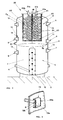
- the accumulation reservoir that is the subject of the invention, which in the sectioned view of Figure 2 is indicated as a whole by 20, comprises a container 2.
- Said container 2 may obviously have any shape and size and its inside is provided with a partition 3 arranged in an intermediate position, which is preferably a diaphragm 3a.
- the partition 3 defines in the container 2 an upper chamber 4 and a lower chamber 5, communicating with each other at the level of the external perimeter of the partition 3, whose cross section is smaller than the inner cross section of the container 2.
- the partition 3 may occupy the whole cross section of the container 2 and comprise one or more through holes ensuring communication between the two chambers 4, 5.
- the container 2 is also provided with an inlet passage 6 communicating with the upper chamber 4 and an outlet way 7 communicating with the lower chamber 5, as well as a plurality of delivery passages 8 and return passages 9, arranged at different heights on the container 2.
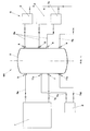
- FIG. 1 which illustrates by way of example the generic diagram of a heating system
- the inlet and outlet passages 6, 7 are respectively connected to a delivery passage 6a and to a return passage 7a of a heating unit T that heats the fluid F contained in the container 2.
- Each delivery passage 8, instead, conveys the fluid to a corresponding inlet passage 8a of external heat exchange means S, whose outlet passages 9a are connected to the return passages 9 of the container 2.
- delivery passage 8 and return passage 9 may be provided in any number, that is, may be one or more than one, depending on the complexity of the system.
- inlet passage 6 there may be more than one inlet passage 6 and more than one outlet passage 7, communicating with one or more heating units T.
- overlapping partitions 3 may be provided, in order to define more than two chambers 4, 5 inside the container 2.
- the first heat exchanger 21 is provided with an inlet passage 22a and an outlet passage 22b for the circulation of a first auxiliary fluid Fa which receives heat from the fluid F contained in the container 2.
- the above mentioned first auxiliary fluid Fa can be, for example, sanitary water.
- the first heat exchanger 21 is a coil 22, provided with inlet passages 22a and outlet passages 22b for the first auxiliary fluid Fa, arranged on the cover of the container 2.
- the coil 22 is wound to form a first helix 23 and a second helix 24, preferably but not necessarily cylindrical, the second helix 24 being arranged inside the first helix 23.
- the first auxiliary fluid Fa flows in succession through the two helices 23, 24 in opposite directions, that is, flows down one helix and up the other one.
- the auxiliary fluid Fa exchanges heat with the hot fluid F for a longer time and therefore absorbs from it a greater quantity of heat.
- the reservoir 20 that is the subject of the invention particularly suitable for use in the production of hot sanitary water when low temperature heat sources are available, like, for example, solar panels or heat pumps.
- the reservoir 20 of the invention makes it possible to supply a higher flow rate compared to the reservoirs of known type.
- the double helix defined by the first heat exchanger 21 has a larger heat exchange surface compared to the heat exchangers of the reservoirs of known type having the same size, thus further increasing the heating efficiency.
- the first heat exchanger 21 is preferably contained in the upper chamber 4 of the container 2.
- the fact that the heat exchange takes place in the upper chamber 4, where the temperature of the fluid F is higher, further favours the efficiency of the first heat exchanger 21.
- the first heat exchanger 21, being arranged in the upper chamber 4, does not interfere with the partition 3 that, therefore, can have any size in order to advantageously favour the stratification of the fluid F.
- the absence of interference between the partition 3 and the first heat exchanger 21 makes it possible to remove the latter comfortably during maintenance operations.
- the heat exchanger 21 can be arranged differently than described above, for example extend also into the lower chamber 5, and if necessary develop for the entire height of the container 2.
- the coil 22 is preferably constituted by a pair of flexible metal pipes arranged side by side.
- the flexible pipe is easier to clean, in particular as regards the removal of scale.
- the coil 22 may comprise a single flexible metal pipe, or even more than two metal pipes.
- the flexible pipes are preferably supported by a frame 25 arranged inside the container 2, preferably made of steel parts and comprising a central core contained in an external cage, joined together by cross elements suited to delimit a space that houses the flexible pipes.
- the coil is constituted by four rigid metal pipes arranged side by side and not by flexible pipes.
- the coil may comprise more than four metal pipes.
- Figure 5 illustrates a construction variant of the reservoir that is the subject of the invention, indicated as a whole by 60 and comprising also two second heat exchangers 31, 32, respectively arranged in each chamber 4, 5 of the container 2 in contact with the fluid F.
- Each one of the second heat exchangers 31, 32 defines an inlet passage 31a, 32a and an outlet passage 31 b, 32b for the circulation of a second auxiliary fluid Fb, Fc.
- the second heat exchangers 31, 32 can be connected to auxiliary heat sources like, for example, sets of solar panels, indicated by P in Figure 1 , or any other heat source, to heat the fluid F.
- said second heat exchangers 31, 32 make it possible to recover the heat coming from auxiliary heat sources, accumulating it in the fluid F present in the reservoir 60 and further reducing the frequency of the starts of the main heating unit T.
- the lower second heat exchanger 32 is preferably connected to a set of solar panels P or to a heat pump, not illustrated herein, that usually supply heat at low temperature, while the upper second heat exchanger 31 is connected to a heat source at higher temperature, like for example a chimney with heat exchanger.
- the two second heat exchangers 31, 32 may be connected to any type of heat source, or even be both connected, in series or in parallel, to the same heat source.
- connection to be made is up to the designer or installer, depending on the available heat sources and on the requirements of the system.
- the reservoir 50 may be provided with a single second heat exchanger 32, preferably arranged in the lower chamber 5 of the container 2.
- each second heat exchanger 31, 32 is made up of one rigid metal pipe wound to form a coil 33, 34.
- the upper second heat exchanger 31 is arranged outside the first heat exchanger 21 present therein.
- all the above mentioned variants of reservoir 20, 50, 60 comprise also anti-turbulence means 10, arranged inside the container 2 and immersed in the fluid F in order to prevent it from being excessively mixed inside the container 2 itself and thus to advantageously maintain its stratification.
- the anti-turbulence means 10 preferably comprise a manifold chamber 13 arranged at the level of each delivery passage 8 and of the inlet and outlet passages 6 and 7, which reduces the turbulence generated by the fluid F while it flows through them.
- each manifold chamber 13 is constituted by a box-shaped container 13a applied to the inner wall of the container 2 and provided with openings 13b communicating with the inside of the container 2 itself.
- the above mentioned openings are adjacent to the inner wall of the container 2 and arranged according to substantially vertical planes.
- the openings 13b oriented as described above determine a withdrawal of fluid F according to a substantially horizontal direction, in such a way as to favour the maintenance of the stratification of the fluid F inside the container 2.
- the anti-turbulence means 10 also comprise a manifold body 14, connected to the inlet passage 9 of the container 2 through a connection pipe 15.
- the manifold body 14 is provided with through holes for the passage of the fluid F, preferably arranged uniformly on the manifold body 14 and aligned according to vertical directions parallel to one another.
- the above mentioned manifold body 14 improves the distribution of the inlet flow in the container 2, thus making it easier to maintain a good stratification in the lower chamber 5, accentuating therein the difference in temperature between the upper and the lower area.
- the above mentioned difference in temperature improves the efficiency of the heat exchange and the promptness of intervention of the heat sources connected to the lower chamber 5, above all when these operate in a limited temperature range, as it happens for example with solar panels.
- the partition 3 As regards the partition 3, it is supported by the manifold body 14, to which it is mechanically connected.
- the partition 3 may be welded to the inner walls of the container 2, or be supported by a frame or analogous supporting means suited to mechanically connect the partition 3 to the container 2.
- the reservoir that is the subject of the invention is also provided with a flange 17, applied to the outside of the container 2, which supports a submersible electric heater, not illustrated herein.
- the invention comprises breather means 18 arranged on the upper part of the container 2 to ensure the discharge of the gases accumulated inside it during operation.
- the reservoir that is the subject of the invention is used in a heating system, an example of which is schematically illustrated in Figure 1 , showing that it comprises the reservoir previously indicated by 60.
- the fluid F contained in the container 2 is maintained at a temperature that is almost constant by means of the heating unit T connected to it.
- the start and stop of the heating unit T are controlled by one or more probes, not illustrated herein, arranged at different heights in the container 2 to measure the temperature of the fluid F.
- the fluid F is taken from the container 2 at different heights and conveyed to external heat exchange means S, some of which belonging to users U like, for example, radiators, fan convectors, floor coils and the like, to which the fluid F transfers heat.
- external heat exchange means S some of which belonging to users U like, for example, radiators, fan convectors, floor coils and the like, to which the fluid F transfers heat.
- the fluid F conveyed to the users U is withdrawn from the upper area of the container 2, where it is available at a higher temperature, and flows back into its lower area.
- One or more of the above mentioned heat exchange means S may also belong to an auxiliary heat source Ta like, for example, a chimney with heat exchanger or any other heat generator of known type, thus allowing the fluid F to be heated in order to advantageously achieve a considerable energy recovery.
- an auxiliary heat source Ta like, for example, a chimney with heat exchanger or any other heat generator of known type, thus allowing the fluid F to be heated in order to advantageously achieve a considerable energy recovery.
- the fluid F is also heated by means of the second auxiliary fluid Fc that flows in the second heat exchanger 32 contained in the container 2, connected with a closed circuit to a set of solar panels P.
- the set of solar panels P can be directly connected to the lower chamber of the container 2.
- the first auxiliary fluid Fa flows in the first heat exchanger 21, independently of the fluid F, passing through the hottest area of the reservoir 60 and getting warmer in such a way as to be able to be used, for example, as hot sanitary water.
- auxiliary fluid Fa flows in succession through the two concentrical cylindrical helices 23, 24 of the first heat exchanger 21, benefiting from a particularly effective heat exchange that makes it possible to exploit in the best possible way the temperature of the fluid F present in the upper chamber 4 of the reservoir 60.
- the double helix configuration of the first heat exchanger makes it possible to create a longer path for the auxiliary fluid and a larger heat exchange surface than in the equivalent reservoirs of known type.
Landscapes
- Engineering & Computer Science (AREA)
- Physics & Mathematics (AREA)
- Thermal Sciences (AREA)
- Mechanical Engineering (AREA)
- General Engineering & Computer Science (AREA)
- Heat-Exchange Devices With Radiators And Conduit Assemblies (AREA)
- Heat-Pump Type And Storage Water Heaters (AREA)
- Filling Or Discharging Of Gas Storage Vessels (AREA)
- Blow-Moulding Or Thermoforming Of Plastics Or The Like (AREA)
Applications Claiming Priority (1)
| Application Number | Priority Date | Filing Date | Title |
|---|---|---|---|
| IT000242A ITVI20070242A1 (it) | 2007-08-29 | 2007-08-29 | Serbatoio di accumulo per fluidi perfezionato |
Publications (2)
| Publication Number | Publication Date |
|---|---|
| EP2031333A2 true EP2031333A2 (fr) | 2009-03-04 |
| EP2031333A3 EP2031333A3 (fr) | 2010-09-29 |
Family
ID=40120159
Family Applications (1)
| Application Number | Title | Priority Date | Filing Date |
|---|---|---|---|
| EP08162883A Withdrawn EP2031333A3 (fr) | 2007-08-29 | 2008-08-25 | Réservoir d'accumulation amélioré pour fluides |
Country Status (2)
| Country | Link |
|---|---|
| EP (1) | EP2031333A3 (fr) |
| IT (1) | ITVI20070242A1 (fr) |
Cited By (8)
| Publication number | Priority date | Publication date | Assignee | Title |
|---|---|---|---|---|
| EP2314970A1 (fr) * | 2009-10-26 | 2011-04-27 | Dritan Ramani | Stockage de chaleur étagé |
| DE202012001555U1 (de) | 2012-02-15 | 2013-02-18 | Pietro Cecchin | Brauchwasser-Kombispeicher |
| US20150276325A1 (en) * | 2012-11-01 | 2015-10-01 | Skanska Sverige Ab | Energy storage |
| DE102014112366A1 (de) * | 2014-08-28 | 2016-03-03 | Krones Ag | Anordnung und Verfahren zur Wärmespeicherung für Wärmeverbraucher in einer Anlage zur Getränkeherstellung und Brauereianlage |
| US9518787B2 (en) | 2012-11-01 | 2016-12-13 | Skanska Svergie Ab | Thermal energy storage system comprising a combined heating and cooling machine and a method for using the thermal energy storage system |
| US9823026B2 (en) | 2012-11-01 | 2017-11-21 | Skanska Sverige Ab | Thermal energy storage with an expansion space |
| CN111194391A (zh) * | 2017-07-17 | 2020-05-22 | 莱兹厄尔斯私人有限公司 | 热水箱 |
| CN116237346A (zh) * | 2022-12-30 | 2023-06-09 | 中国化学工程重型机械化有限公司 | 一种固体废弃物的热解系统 |
Family Cites Families (5)
| Publication number | Priority date | Publication date | Assignee | Title |
|---|---|---|---|---|
| DE29517528U1 (de) * | 1994-10-31 | 1995-12-21 | Joh. Vaillant Gmbh U. Co, 42859 Remscheid | Speicher |
| DE19903442A1 (de) * | 1999-01-29 | 2000-08-10 | Reflex Winkelmann & Pannhoff G | Warmwasserspeicher |
| CZ298909B6 (cs) * | 2001-03-30 | 2008-03-12 | Tepelný akumulátor obsahující výmeník tepla | |
| DE20113633U1 (de) * | 2001-08-17 | 2002-01-10 | Heiß, Rudolf, 85669 Pastetten | Wärmespeicher und Heizanlage |
| DE20311580U1 (de) * | 2003-07-25 | 2003-12-04 | Nothaft, Hermann | Zonenschichtspeicher, insbesondere zur solaren Beladung |
-
2007
- 2007-08-29 IT IT000242A patent/ITVI20070242A1/it unknown
-
2008
- 2008-08-25 EP EP08162883A patent/EP2031333A3/fr not_active Withdrawn
Cited By (16)
| Publication number | Priority date | Publication date | Assignee | Title |
|---|---|---|---|---|
| EP2314970A1 (fr) * | 2009-10-26 | 2011-04-27 | Dritan Ramani | Stockage de chaleur étagé |
| DE202012001555U1 (de) | 2012-02-15 | 2013-02-18 | Pietro Cecchin | Brauchwasser-Kombispeicher |
| DE202013001469U1 (de) | 2012-02-15 | 2013-04-25 | Pietro Cecchin | Brauchwasser-Kombispeicher |
| US9823026B2 (en) | 2012-11-01 | 2017-11-21 | Skanska Sverige Ab | Thermal energy storage with an expansion space |
| US20150276325A1 (en) * | 2012-11-01 | 2015-10-01 | Skanska Sverige Ab | Energy storage |
| US9518787B2 (en) | 2012-11-01 | 2016-12-13 | Skanska Svergie Ab | Thermal energy storage system comprising a combined heating and cooling machine and a method for using the thermal energy storage system |
| US9657998B2 (en) | 2012-11-01 | 2017-05-23 | Skanska Sverige Ab | Method for operating an arrangement for storing thermal energy |
| US9791217B2 (en) * | 2012-11-01 | 2017-10-17 | Skanska Sverige Ab | Energy storage arrangement having tunnels configured as an inner helix and as an outer helix |
| DE102014112366A1 (de) * | 2014-08-28 | 2016-03-03 | Krones Ag | Anordnung und Verfahren zur Wärmespeicherung für Wärmeverbraucher in einer Anlage zur Getränkeherstellung und Brauereianlage |
| CN111194391A (zh) * | 2017-07-17 | 2020-05-22 | 莱兹厄尔斯私人有限公司 | 热水箱 |
| EP3655711A4 (fr) * | 2017-07-17 | 2020-10-21 | Wise Earth Pty Ltd | Réservoir d'eau chaude |
| GB2578409B (en) * | 2017-07-17 | 2021-11-17 | Wise Earth Pty Ltd | Hot water tank |
| CN111194391B (zh) * | 2017-07-17 | 2022-11-01 | 莱兹厄尔斯私人有限公司 | 热水箱 |
| US11549693B2 (en) | 2017-07-17 | 2023-01-10 | Wise Earth Pty Ltd | Hot water tank |
| AU2018303334B2 (en) * | 2017-07-17 | 2023-02-23 | Wise Earth Pty Ltd | Hot water tank |
| CN116237346A (zh) * | 2022-12-30 | 2023-06-09 | 中国化学工程重型机械化有限公司 | 一种固体废弃物的热解系统 |
Also Published As
| Publication number | Publication date |
|---|---|
| EP2031333A3 (fr) | 2010-09-29 |
| ITVI20070242A1 (it) | 2009-02-28 |
Similar Documents
| Publication | Publication Date | Title |
|---|---|---|
| EP2031333A2 (fr) | Réservoir d'accumulation amélioré pour fluides | |
| EP2082174A1 (fr) | Appareil et procédé de chauffe-eau | |
| MX2013004478A (es) | Calentador de agua de bomba de calor montado en base endotermica. | |
| EP3172497B1 (fr) | Chauffe-eau et applications correspondantes | |
| EP2965022B1 (fr) | Échangeur de chaleur | |
| WO2008027041A1 (fr) | Réservoir de stockage d'eau à sections multiples avec stratification thermique pour systèmes d'utilisation d'énergie thermique | |
| KR20110084889A (ko) | 세척 기구 | |
| GB2539912A (en) | Heat recovery device | |
| WO2004070286A2 (fr) | Systeme pour chauffer des liquides | |
| EP3286503B1 (fr) | Système de chaudière | |
| JP4251172B2 (ja) | ヒートポンプ給湯装置 | |
| DK2815196T3 (en) | Heat exchange to heat or central heating system | |
| EP3356747B1 (fr) | Chauffe-eau à combustible | |
| AU2011320032B2 (en) | Heating apparatus | |
| EP3097366B1 (fr) | Chaudière sectionnable | |
| US7997236B2 (en) | Water heater and a method of operating same | |
| WO2008111722A1 (fr) | Chaudière électrique | |
| KR200466598Y1 (ko) | 전기 온수 보일러 | |
| EP4513102A1 (fr) | Module d'interface pour un système hydronique | |
| EP3943831B1 (fr) | Chauffe-eau bi-fonctionel | |
| JP2004020014A (ja) | 給湯装置 | |
| KR101018206B1 (ko) | 온풍기용 열교환기 | |
| CN218065085U (zh) | 一种生活热水换热机组 | |
| KR200458553Y1 (ko) | 온수 매트 장치 | |
| FI127668B (fi) | Patteri jossa on parannettu lämmönsiirtoaineen virtaus sekä menetelmä virtauksen parantamiseksi patterissa |
Legal Events
| Date | Code | Title | Description |
|---|---|---|---|
| PUAI | Public reference made under article 153(3) epc to a published international application that has entered the european phase |
Free format text: ORIGINAL CODE: 0009012 |
|
| AK | Designated contracting states |
Kind code of ref document: A2 Designated state(s): AT BE BG CH CY CZ DE DK EE ES FI FR GB GR HR HU IE IS IT LI LT LU LV MC MT NL NO PL PT RO SE SI SK TR |
|
| AX | Request for extension of the european patent |
Extension state: AL BA MK RS |
|
| PUAL | Search report despatched |
Free format text: ORIGINAL CODE: 0009013 |
|
| AK | Designated contracting states |
Kind code of ref document: A3 Designated state(s): AT BE BG CH CY CZ DE DK EE ES FI FR GB GR HR HU IE IS IT LI LT LU LV MC MT NL NO PL PT RO SE SI SK TR |
|
| AX | Request for extension of the european patent |
Extension state: AL BA MK RS |
|
| RIC1 | Information provided on ipc code assigned before grant |
Ipc: F28D 7/02 20060101ALI20100826BHEP Ipc: F28D 20/00 20060101AFI20081218BHEP |
|
| AKY | No designation fees paid | ||
| REG | Reference to a national code |
Ref country code: DE Ref legal event code: R108 Effective date: 20110503 |
|
| STAA | Information on the status of an ep patent application or granted ep patent |
Free format text: STATUS: THE APPLICATION IS DEEMED TO BE WITHDRAWN |
|
| 18D | Application deemed to be withdrawn |
Effective date: 20110330 |