EP2031441A2 - Kamerabelichtungssteuerung - Google Patents
Kamerabelichtungssteuerung Download PDFInfo
- Publication number
- EP2031441A2 EP2031441A2 EP08015061A EP08015061A EP2031441A2 EP 2031441 A2 EP2031441 A2 EP 2031441A2 EP 08015061 A EP08015061 A EP 08015061A EP 08015061 A EP08015061 A EP 08015061A EP 2031441 A2 EP2031441 A2 EP 2031441A2
- Authority
- EP
- European Patent Office
- Prior art keywords
- brightness
- image
- imaging region
- imaging
- axis
- Prior art date
- Legal status (The legal status is an assumption and is not a legal conclusion. Google has not performed a legal analysis and makes no representation as to the accuracy of the status listed.)
- Granted
Links
Images


Classifications
-
- B—PERFORMING OPERATIONS; TRANSPORTING
- B25—HAND TOOLS; PORTABLE POWER-DRIVEN TOOLS; MANIPULATORS
- B25J—MANIPULATORS; CHAMBERS PROVIDED WITH MANIPULATION DEVICES
- B25J19/00—Accessories fitted to manipulators, e.g. for monitoring, for viewing; Safety devices combined with or specially adapted for use in connection with manipulators
- B25J19/02—Sensing devices
- B25J19/021—Optical sensing devices
- B25J19/022—Optical sensing devices using lasers
-
- G—PHYSICS
- G03—PHOTOGRAPHY; CINEMATOGRAPHY; ANALOGOUS TECHNIQUES USING WAVES OTHER THAN OPTICAL WAVES; ELECTROGRAPHY; HOLOGRAPHY
- G03B—APPARATUS OR ARRANGEMENTS FOR TAKING PHOTOGRAPHS OR FOR PROJECTING OR VIEWING THEM; APPARATUS OR ARRANGEMENTS EMPLOYING ANALOGOUS TECHNIQUES USING WAVES OTHER THAN OPTICAL WAVES; ACCESSORIES THEREFOR
- G03B35/00—Stereoscopic photography
- G03B35/08—Stereoscopic photography by simultaneous recording
-
- G—PHYSICS
- G03—PHOTOGRAPHY; CINEMATOGRAPHY; ANALOGOUS TECHNIQUES USING WAVES OTHER THAN OPTICAL WAVES; ELECTROGRAPHY; HOLOGRAPHY
- G03B—APPARATUS OR ARRANGEMENTS FOR TAKING PHOTOGRAPHS OR FOR PROJECTING OR VIEWING THEM; APPARATUS OR ARRANGEMENTS EMPLOYING ANALOGOUS TECHNIQUES USING WAVES OTHER THAN OPTICAL WAVES; ACCESSORIES THEREFOR
- G03B7/00—Control of exposure by setting shutters, diaphragms or filters, separately or conjointly
- G03B7/08—Control effected solely on the basis of the response, to the intensity of the light received by the camera, of a built-in light-sensitive device
- G03B7/091—Digital circuits
- G03B7/093—Digital circuits for control of exposure time
-
- H—ELECTRICITY
- H04—ELECTRIC COMMUNICATION TECHNIQUE
- H04N—PICTORIAL COMMUNICATION, e.g. TELEVISION
- H04N13/00—Stereoscopic video systems; Multi-view video systems; Details thereof
- H04N13/20—Image signal generators
- H04N13/204—Image signal generators using stereoscopic image cameras
- H04N13/239—Image signal generators using stereoscopic image cameras using two two-dimensional [2D] image sensors having a relative position equal to or related to the interocular distance
-
- H—ELECTRICITY
- H04—ELECTRIC COMMUNICATION TECHNIQUE
- H04N—PICTORIAL COMMUNICATION, e.g. TELEVISION
- H04N13/00—Stereoscopic video systems; Multi-view video systems; Details thereof
- H04N13/20—Image signal generators
- H04N13/296—Synchronisation thereof; Control thereof
-
- H—ELECTRICITY
- H04—ELECTRIC COMMUNICATION TECHNIQUE
- H04N—PICTORIAL COMMUNICATION, e.g. TELEVISION
- H04N23/00—Cameras or camera modules comprising electronic image sensors; Control thereof
- H04N23/70—Circuitry for compensating brightness variation in the scene
- H04N23/71—Circuitry for evaluating the brightness variation
-
- H—ELECTRICITY
- H04—ELECTRIC COMMUNICATION TECHNIQUE
- H04N—PICTORIAL COMMUNICATION, e.g. TELEVISION
- H04N23/00—Cameras or camera modules comprising electronic image sensors; Control thereof
- H04N23/70—Circuitry for compensating brightness variation in the scene
- H04N23/73—Circuitry for compensating brightness variation in the scene by influencing the exposure time
Definitions
- This invention relates to a camera exposure controller, particularly to an exposure controller for a camera mounted on a mobile object.
- a camera of this type is also sometimes used as a visual sensor mounted on a mobile robot or other mobile object.
- the exposure parameters are adjusted based on distance information.
- a bright light source such as the sun or a spotlight is present within the camera angle of view as shown in FIG. 19
- an attempt to avoid brightness saturation by increasing the shutter speed and/or stopping down the lens (iris-out) blots out the brightness of the object to be imaged, so that an image suitable for imaged object extraction or other processing sometimes cannot be obtained.
- a human being actually present on the right side of the image cannot be discerned.
- the object of this invention is to overcome this problem and to provide an exposure controller for a camera mounted on a mobile object that enables the camera to image an object with suitable brightness even when a bright light source such as the sun is within the camera angle of view.
- this invention provides a camera exposure controller having at least two imaging devices mounted on a mobile object for taking an image, through stereo-imaging, utilizing incident light from external world in which an object of imaging is present, comprising: exposure parameter setting means for generating a brightness histogram of the image taken by the imaging devices and setting exposure parameters including a shutter speed based on the generated brightness histogram; high-brightness imaging region removal necessity determining means for determining whether the set exposure parameters are within a predetermined range, and when they are found to be out of the predetermined range, for determining whether a high-brightness imaging region is present in the image due to high-brightness incident light, and when the high-brightness imaging region is present in the image, for determining whether it is necessary to remove the high-brightness imaging region; and high-brightness imaging region extraction and removal means for extracting the high-brightness imaging region and for removing it from the image, when it is determined that removal of the high-brightness imaging region is necessary.
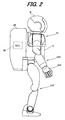
- FIG. 1 is a front view of a legged mobile robot, i.e., a mobile object, on which a camera exposure controller according to a first embodiment of this invention is mounted.
- FIG. 2 is a side view of the robot shown in FIG. 1 .
- the legged mobile robot (mobile object), designated by the reference symbol 10 in the drawings and sometimes referred to simply as “robot” hereinafter, is equipped with left and right legs 12L, 12R.
- L and R are used to indicate left and right.
- the legs 12L, 12R are connected to the bottom of a body 14.
- a head 16 is connected to the top of the body 14 and left and right arms 20L, 20R are connected to opposite sides of the body 14.
- Hands (end effectors) 22L, 22R are connected to the distal ends of the left and right arms 20L, 20R.
- the legged mobile robot is exemplified by a humanoid robot that has two legs and two arms and stands to a height of about 1.3 m.
- a storage unit 24 is mounted on the back of the body 14.
- the storage unit 24 houses, inter alia, an Electronic Control Unit (ECU) 26 and a battery (not shown).
- ECU Electronic Control Unit
- FIG. 3 is an explanatory diagram showing a skeletonized view of the robot 10 shown in FIG. 1 .
- the internal structures of the robot 10 will be explained with reference to this drawing, with primary focus on the joints. Since the illustrated robot 10 is laterally symmetrical, affixation of L and R will be omitted in the explanation of FIG 3 .
- the left and right legs 12 are each equipped with a thigh link 30, a shank link 32, and a foot member 34.
- the thigh link 30 is connected to the body 14 through a hip (crotch) joint.
- the body 14 is shown schematically in FIG. 3 as a body link 36.
- the body link 36 comprises an upper section 36a and a lower section 36b connected through a joint 38 to be movable relative to each other.
- the thigh link 30 and shank link 32 are connected through a knee joint.
- the shank link 32 and the foot 34 are connected through an ankle joint.
- the hip joint comprises a rotary shaft 40 rotatable about a Z-axis (yaw axis), a rotary shaft 42 rotatable about a Y-axis (pitch axis), and rotary shaft 44 rotatable about an X-axis (roll axis).
- the hip joint has three degrees of freedom.
- the knee joint comprises a rotary shaft 46 rotatable about the Y-axis and has one degree of freedom.
- the ankle joint comprises a rotary shaft 48 rotatable about the Y-axis and a rotary shaft 50 rotatable about the X-axis and has two degrees of freedom.
- the left and right legs 12 are each imparted with 6 rotary shafts (degrees of freedom) constituting 3 joints, so that the legs as a whole are imparted with 12 rotary shafts (degrees of freedom).
- the legs 12 are driven by actuators (not shown).
- the leg actuators that drive the legs 12 comprise 12 electric motors installed at appropriate locations on the body 14 and legs 12 to drive the 12 rotary shafts independently.
- the left and right arms 20 are each equipped with an upper arm link 52 and a forearm link 54.
- the upper arm link 52 is connected to the body 14 through a shoulder joint.
- the upper arm link 52 and forearm link 54 are connected through an elbow joint, and the forearm link 54 and hand 22 are connected through a wrist joint.
- the shoulder joint comprises a rotary shaft 56 rotatable about the Y-axis, a rotary shaft 58 rotatabale about the X-axis, and a rotary shaft 60 rotatable about the Z-axis. It has three degrees of freedom.
- the elbow joint comprises a rotary shaft 62 rotatable about the Y-axis and has one degree of freedom.
- the wrist joint comprises a rotary shaft 64 rotatable about the Z-axis, a rotary shaft 66 rotatable about the Y-axis, and a rotary shaft 68 rotatable about the X-axis. It has three degrees of freedom.
- the left and right arms 20 are each imparted with 7 rotary shafts (degrees of freedom) constituting 3 joints, so that the arms as a whole are imparted with 14 rotary shafts (degrees of freedom).
- the arms 20 are also driven by actuators (not shown).
- the arm actuators that drive the arms 20 comprise 14 electric motors installed at appropriate locations on the body 14 and arms 20 to drive the 14 rotary shafts independently.
- the legs 12 and arms 20 of the robot 10 are imparted with desired movements by being controlled the operation of the leg actuators and arm actuators to drive the rotary shafts to suitable angles.
- the hands 22 are each equipped with 5 fingers generally designated by the reference symbol 70.
- the fingers 70 are drivable by hand actuators (not shown) and can be operated in coordination with the arms 20 to grasp objects, point in a suitable direction and execute other such operations.
- the head 16 is connected to the body 14 through a neck joint that comprises a rotary shaft 72 rotatable about the Z-axis and a rotary shaft 74 rotatable about the Y-axis. It has two degrees of freedom.
- the rotary shafts 72 and 74 are individually driven by head actuators (not shown).
- the head 16 can be faced in a desired direction by being controlled the operation of the head actuators to drive the rotary shafts 72 and 74 to suitable angles.
- the upper section 36a and lower section 36b can be rotated relative to each other by driving an actuator (not shown) installed at the joint 38.
- a force sensor (six-axis force sensor) 76 attached to each of the left and right legs 12 produces outputs or signals representing the floor reaction force components Fx, Fy and Fz of three directions and the moment components Mx, My and Mz of three directions acting on the leg 12 from the floor.
- a similar force sensor 78 attached to each of the left and right arms 20 between the hand 22 and the wrist joint produces outputs or signals representing the external force components Fx, Fy and Fz of three directions and the moment components Mx, My and Mz of three directions acting on the arm 20.
- An inclination sensor 80 installed on the body 14 produces outputs or signals representing state quantities of the body 14, including its inclination angle and angular velocity relative to the vertical axis.
- Two (left and right) CCD cameras (hereinafter sometimes called simply “cameras") 82 are installed in the head 16 for taking images utilizing incident light from the external world (ambience) in which a human being or other object to be imaged is present.
- a voice input/output device 84 comprising a microphone 84a and a speaker 84b is also installed in the head 16.
- the outputs of the sensors and the like are sent to the ECU 26 (shown in FIG. 2 ).
- the ECU 26 is constituted as a microcomputer comprising a CPU, input/output circuits, ROM, RAM and other components, none of which are shown in the drawings.
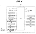
- FIG. 4 is a block diagram showing the configuration of the robot 10 primarily with regard to input/output of the ECU 26.
- the robot 10 is equipped not only with the aforesaid sensors an the like but also with rotary encoders 86, a gyro-sensor 88, a Global Positioning System (GPS) receiver 90, and an IC tag signal receiver (reader) 94 wirelessly connected to an IC tag 92 carried (worn) by a human being (object of imaging) for receiving Integrated Circuit (IC) tag information transmitted by the IC tag 92.
- GPS Global Positioning System
- the rotary encoders 86 produce outputs or signals indicative of the rotation angles, i.e. joint angles, of the respective rotary shafts 40 and the like.
- the gyro-sensor 88 produces an output or signal indicative of the direction and distance of movement of the robot 10.
- the GPS receiver 90 receives radio signals transmitted from satellites, acquires information on the position (latitude and longitude) of the robot 10, and sends the position information to the ECU 26.
- the IC tag signal receiver 94 wirelessly receives and sends to the ECU 26 identification information (RFID (Radio Frequency ID) information, specifically identification information identifying the human being who is the wearer of the IC tag 92)) stored in and transmitted from the IC tag 92.
- RFID Radio Frequency ID
- the ECU 26 controls walking by generating a gait based on the outputs of the force sensors 76, inclination sensor 80, and rotary encoders 86. Specifically, it makes the robot 10 move (walk) by controlling the operation of leg actuators (designated 100) to drive the legs 12.
- the gait generation and walking control is performed in accordance with the teaching of Applicant's Japanese Patent No. 3726081 and will not be explained in detail here.
- the ECU 26 Concomitantly with the walking and other control, the ECU 26 further controls the operation of the arm actuators (designated 102) and the hand actuators (designated 104), thereby driving the arms 20 and hands 22, and controls the operation of the head actuators (designated 106), thereby regulating the orientation of the head 16.
- the ECU 26 operates as an exposure controller of the cameras 82. Namely, it executes exposure control of the camera 82.
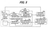
- FIG. 5 is a block diagram functionally illustrating the configuration when the ECU 26 operates as the exposure controller of the cameras 82.
- the ECU 26 comprises a stereo processor 26a, a histogram generator 26b, an exposure parameter setting unit 26c, a high-brightness imaging region removal necessity determiner 26d, a high-brightness imaging region extractor 26e, an image processor 26f, and a behavior generator 26g.
- the stereo processor 26a inputs the outputs of the two cameras (imaging devices) 82 mounted on the mobile object (robot) 10 and adapted to take images utilizing incident light from the external world in which an object (of imaging), specifically a human being, is present. Upon inputting the outputs, it performs stereo processing to calculate distance information for each pixel from the parallax of the inputted images.
- the number of pixels of the cameras 82 is 320 x 240.
- the stereo processor 26a calculates and outputs three-dimensional (3D) data from gray-scale image data.
- the histogram generator 26b creates brightness histograms of the taken images and weights them by distance or in accordance with distance.
- the exposure parameter setting unit 26c defines an exposure parameter (specifically, shutter speed) based on the brightness at the distance desired to be imaged. Owing to the fact that the cameras 82 are installed in the robot 10 to function as a visual sensor, the cameras 80 do not themselves seek out objects (of imaging) but are required to extract objects (of imaging) from taken images. So the lenses of the cameras 82 are fixed at the smallest aperture (the iris is set to the minimum) and are adjusted to be in focus at a near distance, specifically between about 0.5 m and 2.5 m. Therefore, only the shutter speed is adjustable as an exposure parameter.
- shutter speed is adjustable as an exposure parameter.
- the high-brightness imaging region removal necessity determiner 26d determines whether it is necessary for obtaining proper exposure for imaging the object to remove from the image a high-brightness imaging region imaged therein due to high-brightness incident light.
- the high-brightness imaging region extractor 26e extracts the high-brightness imaging region and calculates the position and angle of the high-brightness imaging region in a stage coordinate system, namely, a rectangular coordinate system whose x, y plane is the floor and whose origin is a point in the image area based on camera parameters of the cameras 82, when it is determined that removal of the high-brightness imaging region from the image is necessary.
- the high-brightness imaging region extraction is performed either by defining a region where the average brightness is greater than a threshold value as a high-brightness imaging region or by dividing the image into predetermined blocks, calculating the average brightnesses of the individual blocks and defining the block with the highest brightness as the center of a high-brightness imaging region.
- the image processor 26f is responsive to movement of the robot 10 for performing image processing as a visual sensor.
- the behavior generator 26g generates a predetermined behavior of the robot 10 for removing the high-brightness imaging region from the image, based on the size and the like of the high-brightness imaging region.
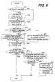
- FIG. 6 is a flowchart showing the processing when the ECU 26 operates as the exposure controller of the cameras 82.
- the illustrated program is executed at desired time intervals of, for example, 1 millisecond to 300 milliseconds.
- S10 it is checked whether an object (of imaging, i.e., a human being), is present.
- the presence/absence of an object (of imaging) is determined from the output of the IC tag signal receiver 94, which receives identification information transmitted by the IC tag 92 borne (worn) by the human being.
- the program goes to S12, in which the brightness of the image of the object (of imaging) taken by the cameras 82, specifically of the object (of imaging) in the image, is calculated, and to S14, in which the maximum brightness of the whole image including the object (of imaging) is calculated.
- S12 the brightness of the image of the object (of imaging) taken by the cameras 82, specifically of the object (of imaging) in the image
- S14 the maximum brightness of the whole image including the object (of imaging) is calculated.
- the calculated brightnesses are compared.
- the program goes to S 18, in which a region where the maximum brightness is present is defined as the high-brightness imaging region, and when the brightness of the object (of imaging) is larger, the program goes to S20, in which a region where the object is present is defined as the high-brightness imaging region (In other words, the processing from S16 to S20 is amount to determining whether the high-brightness imaging region is present in the image).
- the processing from S 10 to S20 is performed by the stereo processor 26a of FIG. 5 .
- S22 processing for setting the exposure parameters is performed.
- FIG. 7 is a subroutine flowchart of this processing, which is executed by the histogram generator 26b and exposure parameter setting unit 26c.
- the object pixels are extracted.
- Object pixels as termed here means pixels carrying information for the distance at which exposure is to be adjusted.
- the extraction of the object pixels amounts to generating a brightness histogram of the image obtained by imaging the object (of imaging).
- the threshold value A is a value set beforehand by calculating the area of the total image area to be accounted for by the object (of imaging) at the distance at which exposure is to be adjusted.
- the program then goes to S 112, in which the counter value is incremented.
- Previous frame average is the value obtained by averaging the brightnesses of all pixels (pixels of the whole image area) of several frames of images (frames) taken at 200 millisecond intervals in the past
- Extracted pixel number is the number of pixels extracted in S100
- Regular pixel number is the total number of pixels (pixels of the whole image area) including the extracted pixels
- Coefficient is a correction coefficient derived from experience
- Current frame average is the value obtained by averaging the brightnesses of all pixels (pixels of the whole image area) imaged in the current cycle. Since, as pointed out earlier, all of the pixels carry distance information, the averaging of the pixel brightnesses is also performed taking distance into account.
- the average brightness calculated in S104 for example, is less than an appropriately set threshold value C, or is greater than a threshold value D.
- the threshold values C and D are set by empirically selecting values that enable image processing.
- the shutter speed shift amount is calculated to make the average brightness fall midway between the threshold value C and the threshold value D.
- Coefficient 1 is a correction coefficient determined from experience. As explained earlier, the lenses of the cameras 82 are fixed at the smallest aperture (i.e., the minimum iris) and only the shutter speed is made adjustable as an exposure parameter.
- the Coefficients 2 and 3 in Eq. 5 and Eq. 6 are also correction coefficients determined from experience.
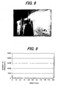
- the controller in this embodiment is directed to dealing with the problem of imaging an object (of imaging) at appropriate brightness in a situation where external light from the sun, for instance, enters through the incident light window to appear in the image, as shown in FIG. 8 by way of example.
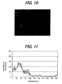
- a parallax image like that shown in FIG. 10 is obtained and a distance-weighted brightness histogram like that shown in FIG. 11 is calculated.
- a distance-weighted brightness histogram like that shown in FIG. 11
- the histogram shown in FIG. 11 when the value of pixels near the cameras 82 are emphasized, the frequency of white-out and black-out is substantially the same to optimize exposure adjustment.
- the image shown in FIG. 8 was obtained by adjusting exposure based on such a distance-weighted brightness histogram.
- the object (of imaging) when the object (of imaging) once comes to be present in the image as shown in FIG 8 , it may thereafter disappear from the image with time-course movement. Therefore, when the result in S 102 is YES, meaning that the object (of imaging) is present in the image, or when the result in S102 is NO but the counter value is found in S108 to be less than the threshold value B (e.g., several frames), the average brightness is calculated as a weighted average between the average brightness of the current frame and that of the preceding frame (S104 or S110). When the result in S108 is NO, meaning that the counter value is greater than the threshold value, the past imaging data is set aside and the average brightness is defined as the average brightness of the pixels of the whole image (S114).
- the threshold value B e.g., several frames
- the processing of FIG. 7 also encompasses the case of a finding that no object (of imaging) is present and the region where the maximum brightness of the image is present is defined as a high-brightness imaging region. Also in such a case, the result in S108 is NO, and at the time the counter value reaches the threshold value B, the program goes to S 114, in which the average brightness is defined as the average brightness of the pixels of the whole image (S 114).
- the shutter speed shift amount is calculated in accordance with Eq. 4 to fall midway between the two threshold values (S118).
- the reference value is first calculated in accordance with Eq. 5.
- the "number of pixels greater than an effective brightness threshold value" is, for example, the number of pixels whose brightness is greater than 25, and the "number of pixels less than an effective brightness threshold value” is, for example, the number of pixels whose brightness is less than 225.
- the reference value is the difference obtained by subtracting the average for the pixels of brightness greater than 25 and less than 225 from the average brightness, and the amount of change in shutter speed is calculated not as 1/2 of the threshold values C, D but by subtracting this reference value from the average brightness.
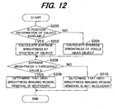
- FIG. 12 is a subroutine flowchart of this determination, which is executed by the high-brightness imaging region removal necessity determiner 26d.
- S200 it is checked whether position information of the object (of imaging) is available. This check is made based on information obtained by the processing in S12 of the flowchart of FIG. 6 or in the flowchart of FIG. 7 .
- the program goes to S202, in which the average brightness at the position of the object (of imaging) is calculated.
- the program goes to S204, in which the average brightness of pixels at relatively short distance in the image, for example, within several meters, is calculated.
- the processing from S200 to S204 is similar to the processing of S10 to S14 in the flowchart of FIG. 6 .
- the program then goes to S206, in which it is checked whether the calculated average brightness is less than a threshold value E.
- the check in S206 is for determining whether the imaging is being done under back-lighting or front-lighting condition. So the threshold value E is set to an appropriate value enabling this check.
- FIG. 13 is a subroutine flowchart of this extraction, which is executed by the high-brightness imaging region extractor 26e.
- the average brightness of every image block of predetermined size is calculated, in other words the average brightnesses of the blocks are calculated one by one.
- “Block” as termed here means a unit area of 10 x 10 pixels.
- the 320 x 240 pixels of the cameras 82 are divided into blocks of this predetermined size (unit area) and the average brightnesses of the blocks are calculated individually.
- the center angle of the high-brightness imaging region i.e., the angle with respect to the calculated center position
- the program goes to S312, in which the size of the high-brightness imaging region is determined to be large, and the determination result and the center angle of the high-brightness imaging region calculated in S310 are outputted.
- the region is determined to be a high-brightness imaging region and the position and angle of the high-brightness imaging region in a stage coordinate system are calculated.
- the program goes to S314, in which the block of largest average brightness among the high-brightness blocks is extracted, to S316, in which the center angle of the high-brightness imaging region, specifically the angle with respect to the extracted block of largest average brightness, is calculated based on camera parameters, and to S318, in which the size of the high-brightness imaging region is determined to be small, and the determination result and the center angle calculated in S316 are outputted.
- the block among individual blocks of the image (of the predetermined size) whose average brightness is largest is determined to be the center of a high-brightness imaging region and the position and angle of the high-brightness imaging region in the stage coordinate system are calculated.
- FIG. 14 is a subroutine flowchart of this processing, which is executed by the behavior generator 26g.
- S400 it is checked whether the size of the high-brightness imaging region outputted in S312 or S318 of the flowchart of FIG. 13 is greater than 1/4 of S, where "S" is the image area.
- the check in S400 is thus for determining whether the size of the high-brightness region is larger than 1/4 the image area.
- this embodiment is configured to have a camera exposure controller having at least two imaging devices (CCD cameras 82) mounted on a mobile object (robot 10) for taking an image, through stereo-imaging, utilizing incident light from external world (ambience) in which an object of imaging, i.e., a human being is present, specifically for taking an image utilizing the principle of stereo-imaging, comprising: exposure parameter setting means for generating a brightness histogram of the image taken by the imaging devices and setting exposure parameters including a shutter speed based on the generated brightness histogram (ECU 26, stereo processor 26a, histogram generator 26b, exposure parameter setting unit 26c, S10 to S22, and S 100 to S122); high-brightness imaging region removal necessity determining means for determining whether the set exposure parameters are within a predetermined range, and when they are found to be out of the predetermined range, for determining whether a high-brightness imaging region is present in the image due to high-brightness incident light, and when the high-b
- the exposure parameter setting means calculates the brightness of the object (of imaging) in the image and the maximum brightness of the whole image, generates the brightness histogram with respect to the calculated brightnesses, and sets the exposure parameters including the shutter speed based on the generated brightness histogram, specifically based on the size of the generated brightness histogram (S10 to S22 and S 100 to S122).
- the controller according to this embodiment having the foregoing effects further enables the exposure parameters to be accurately set even when a bright light source such as the sun is within the angle of view of the cameras 82, thereby enabling the object (of imaging) to be imaged at suitable brightness.
- the object of imaging is a human being and the exposure parameter setting means calculates the brightness of the human being's face and the maximum brightness of the whole image (S10 to S22 and S 100 to S122).
- the exposure parameters can be accurately set not only when a bright light source such as the sun but also when a low-brightness imaging region such as a human face is within the angle of view of the cameras, thereby enabling the object to be imaged at suitable brightness.
- the high-brightness imaging region extraction and removal means extracts the high-brightness imaging region by calculating an average brightness of every block of the image of predetermined size, extracting each block whose calculated average brightness is greater than a predetermined brightness, and by calculating a center position of the extracted blocks (S300 to S312). Owing to this configuration, the controller according to this embodiment having the foregoing effects further enables the high-brightness imaging region imaged due to high-brightness incident light from the sun or the like to be reliably extracted and removed from the image.
- the high-brightness imaging region extraction and removal means calculates an average brightness of every block of the image of predetermined size, extracts one of the blocks whose calculated average brightness is greatest, and extracts the high-brightness imaging region based on the extracted block (S300 to S306 and S314 to S318). Owing to this configuration, the embodiment having the foregoing effects similarly enables the high-brightness imaging region to be reliably extracted and removed from the image.
- the high-brightness imaging region extraction and removal means identifies the position and angle of the high-brightness imaging region in the image and generates a predetermined behavior in the mobile object for removing the identified high-brightness imaging region from the image (S400 to S404). Owing to this configuration, the controller according to this embodiment having the foregoing effects further enables the high-brightness imaging region to be reliably removed from the image.
- FIG. 15 is a partial cross-sectional view of the head 16 of a robot on which a camera exposure controller according to a second embodiment of this invention is mounted and FIG. 16 is a front view thereof.
- the head 16 is covered from the middle to the back by a helmet 16a and its front is covered by a face 16b.
- the helmet 16a is made of opaque and thin hard plastic and the face 16b is made of transparent and thin hard plastic.
- a visor (filter) 16c is installed inward of the face 16b.
- the visor 16c is also made of thin plastic, namely of a thin plastic material that, like a camera ND (Neutral Density) filter, absorbs light of all wavelengths, thereby reducing the amount of light.
- the visor 16c like the face 16b, has a semicircular shape when viewed from the side, and a generally rectangular shape when viewed from the front.
- a drive mechanism 16d is connected to the visor 16c.
- the drive mechanism 16d is mounted inward of and near the opposite edges of the visor 16c. It comprises two racks 16d1 that extend vertically, a single electric motor 16d2 installed near the upper ends of the racks 16d1, pinion gears 16d4 connected to the motor 16d2 through universal joints 16d3 and engaged with the racks 16d1, guides 16.d5 fixed to the opposite ends of the racks 16d1, more precisely to the opposite ends of the visor 16c and guide rails 16d6 (not shown in FIG. 16 ) for guiding the guides 16d5.
- the racks 16d1 are fixed to the visor 16c, driving the racks 16d1 downward lowers the visor 16c, so that, as shown in FIGs. 15 and 16 , it is moved to a position in front of lenses 82a of the cameras 82 located inward of the face 16b, namely to a position on the axes 82b of incident light from the external world in which a human being or other object to be imaged is present, whereby the visor 16c functions as an ND filter for the cameras 82.
- the visor 16c When the drive mechanism 16d is driven in reverse to drive the racks 16d1 upward, the visor 16c is retracted to a standby position inside the helmet 16a (to a position away from the incident light axes (indicated by an imaginary line 16c1)).
- FIG. 18 is a flowchart showing the behavior generation processing of S32 in a flowchart of the second embodiment (not shown) identical to FIG. 6 in the first embodiment.
- the motor 16d2 is operated to lower the visor 16c.
- the visor (filter) 16c is driven to a position on the axes 82b of incident light.
- the visor 16c absorbs light of all wavelengths, i.e., it reduces the amount of light. Owing to this property, it can reduce the brightness of a bright imaging region to enable imaging of a human being or other object (of imaging) at appropriate brightness.
- the second embodiment does not differ from the first embodiment in other structural aspects.
- the second embodiment is configured to have a camera exposure controller having at least two imaging devices (CCD cameras 82) mounted on a mobile object (robot 10) for taking an image, through stereo-imaging, utilizing incident light from external world (ambience) in which an object of imaging, i.e., a human being is present, specifically for taking an image utilizing the principle of stereo-imaging, comprising: exposure parameter setting means for generating a brightness histogram of the image taken by the imaging devices and setting exposure parameters including a shutter speed based on the generated brightness histogram (ECU 26, stereo processor 26a, histogram generator 26b, exposure parameter setting unit 26c, S10 to S22, and S100 to S122); high-brightness imaging region removal necessity determining means for determining whether the set exposure parameters are within a predetermined range, and when they are found to be out of the predetermined range, for determining whether a high-brightness imaging region is present in the image due to high-brightness incident light, and when the high-
- the filter comprises a visor 16c constituted to be movable by a drive mechanism 16d between the position on the axis 82b at a front of a head 16 of the mobile object and the position 16c1 away from the axis at a top of the head 16, and the filter moving means operates the drive mechanism 16d to move the visor 16c to the position on the axis.
- the controller according to the second embodiment having the foregoing effects can further reliably position filter 16c constituted as a visor on the optical axes.
- the drive mechanism 16d comprises at least a rack 16d1 attached to the visor 16c, gears (pinion gears) 16d4 engaged with the rack, and an electric motor 16d2 for driving the gears.
- the filter 16c constituted as a visor can be still more reliably positioned on the axes 82b by means of a simple arrangement.
- the object (of imaging) was presumed to be a human being but it can instead be some other object, such as a tool or workpiece, associated with the task performed by the robot 10.
- the presence/absence of an object (of imaging) is determined from the output of the IC tag signal receiver 94, which receives identification information transmitted by the IC tag 92 carried (worn) by the object (of imaging).
- the determination can instead be made from the output of the cameras 82.
- the robot 10 can be informed of the presence/absence of an object (of imaging) by inputting a command from the outside.
- a legged mobile robot specifically a biped walking robot
- the mobile object can be of any kind capable of moving autonomously.
- a brightness histogram of the image is generated and exposure parameters are set based on the generated histogram (S10 to S22). Then, it is determined whether the set exposure parameters are within a predetermined range and when they are out of the range and if a high-brightness imaging region is present in the image due to high-brightness incident light, it is again determined whether it is necessary to remove the high-brightness imaging region (S24, S26).
- the high-brightness imaging region is extracted and is removed from the image (S28, S30, S32), thereby enabling the camera to image the object with suitable brightness even when a bright light source such as the sun is within the camera angle of view.
Landscapes
- Engineering & Computer Science (AREA)
- Multimedia (AREA)
- Signal Processing (AREA)
- Physics & Mathematics (AREA)
- General Physics & Mathematics (AREA)
- Optics & Photonics (AREA)
- Robotics (AREA)
- Mechanical Engineering (AREA)
- Studio Devices (AREA)
- Image Processing (AREA)
- Manipulator (AREA)
- Image Input (AREA)
Applications Claiming Priority (2)
| Application Number | Priority Date | Filing Date | Title |
|---|---|---|---|
| JP2007224754A JP4847420B2 (ja) | 2007-08-30 | 2007-08-30 | 脚式移動ロボット |
| JP2007224753A JP4933383B2 (ja) | 2007-08-30 | 2007-08-30 | カメラの露出制御装置 |
Publications (3)
| Publication Number | Publication Date |
|---|---|
| EP2031441A2 true EP2031441A2 (de) | 2009-03-04 |
| EP2031441A3 EP2031441A3 (de) | 2009-04-01 |
| EP2031441B1 EP2031441B1 (de) | 2016-04-20 |
Family
ID=40040053
Family Applications (1)
| Application Number | Title | Priority Date | Filing Date |
|---|---|---|---|
| EP08015061.8A Ceased EP2031441B1 (de) | 2007-08-30 | 2008-08-26 | Kamerabelichtungssteuerung |
Country Status (2)
| Country | Link |
|---|---|
| US (1) | US8026955B2 (de) |
| EP (1) | EP2031441B1 (de) |
Cited By (1)
| Publication number | Priority date | Publication date | Assignee | Title |
|---|---|---|---|---|
| CN104105441A (zh) * | 2012-02-13 | 2014-10-15 | 株式会社日立制作所 | 区域提取处理系统 |
Families Citing this family (20)
| Publication number | Priority date | Publication date | Assignee | Title |
|---|---|---|---|---|
| JP2010204304A (ja) * | 2009-03-02 | 2010-09-16 | Panasonic Corp | 撮像装置、運転者監視装置および顔部測距方法 |
| US8244402B2 (en) | 2009-09-22 | 2012-08-14 | GM Global Technology Operations LLC | Visual perception system and method for a humanoid robot |
| CN103112015B (zh) * | 2013-01-29 | 2015-03-04 | 山东电力集团公司电力科学研究院 | 一种适用于工业机器人的操作物位置姿态识别方法 |
| US9615012B2 (en) * | 2013-09-30 | 2017-04-04 | Google Inc. | Using a second camera to adjust settings of first camera |
| US9565416B1 (en) | 2013-09-30 | 2017-02-07 | Google Inc. | Depth-assisted focus in multi-camera systems |
| US10356335B2 (en) * | 2016-09-23 | 2019-07-16 | Apple Inc. | Camera shades |
| JP6936081B2 (ja) * | 2017-08-30 | 2021-09-15 | パナソニック株式会社 | ロボット |
| JP6959277B2 (ja) * | 2019-02-27 | 2021-11-02 | ファナック株式会社 | 3次元撮影装置および3次元撮影条件調整方法 |
| DE112019007983T5 (de) | 2019-12-20 | 2022-12-15 | Honda Motor Co., Ltd. | Arbeitsmaschine und Verarbeitungsvorrichtung |
| JP7504387B2 (ja) * | 2020-03-31 | 2024-06-24 | パナソニックオートモーティブシステムズ株式会社 | 撮像表示システム |
| JP7669128B2 (ja) * | 2020-09-04 | 2025-04-28 | キヤノン株式会社 | 情報処理装置、方法、プログラム及び記憶媒体 |
| CN113014826B (zh) * | 2021-02-18 | 2023-05-05 | 科络克电子科技(上海)有限公司 | 一种图像感光强度参数调整方法、装置、设备及介质 |
| US11962880B2 (en) | 2021-10-29 | 2024-04-16 | Comcast Cable Communications, Llc | Systems and methods for enhanced performance of camera devices |
| US12365094B2 (en) | 2023-04-17 | 2025-07-22 | Figure Ai Inc. | Head and neck assembly for a humanoid robot |
| US12539618B1 (en) | 2023-04-17 | 2026-02-03 | Figure Ai Inc. | Head and neck assembly of a humanoid robot |
| US12605824B2 (en) | 2024-02-26 | 2026-04-21 | Figure Ai Inc. | Humanoid robot |
| WO2025221916A1 (en) * | 2024-04-16 | 2025-10-23 | Figure Ai Inc. | Advanced array of sensor assemblies of a humanoid robot |
| US12578733B2 (en) | 2024-09-04 | 2026-03-17 | Figure Ai Inc. | Bipedal action model for humanoid robot |
| US12611767B2 (en) | 2024-09-06 | 2026-04-28 | Figure Ai Inc. | System and method for efficient control of a humanoid robot |
| US12611766B2 (en) | 2024-09-13 | 2026-04-28 | Figure Ai Inc. | Humanoid robot with advanced kinematics |
Citations (7)
| Publication number | Priority date | Publication date | Assignee | Title |
|---|---|---|---|---|
| US5606630A (en) | 1992-12-28 | 1997-02-25 | Minolta Camera Kabushiki Kaisha | Photographed image reproducing apparatus |
| JP2000341719A (ja) | 1999-05-25 | 2000-12-08 | Mitsubishi Electric Corp | ステレオカメラ |
| EP1087205A2 (de) | 1999-09-22 | 2001-03-28 | Fuji Jukogyo Kabushiki Kaisha | Stereo-Abstandsmesser |
| US20040041928A1 (en) | 2002-06-19 | 2004-03-04 | Hiroto Hirakoso | Image processing apparatus, camera apparatus, and automatic exposure control method |
| JP2004343177A (ja) | 2003-05-13 | 2004-12-02 | Minolta Co Ltd | 撮像装置 |
| US20050140819A1 (en) | 2003-12-25 | 2005-06-30 | Niles Co., Ltd. | Imaging system |
| JP2006129084A (ja) | 2004-10-28 | 2006-05-18 | Canon Inc | 撮像装置及び撮像方法 |
Family Cites Families (29)
| Publication number | Priority date | Publication date | Assignee | Title |
|---|---|---|---|---|
| JPH07212645A (ja) * | 1994-01-25 | 1995-08-11 | Hitachi Denshi Ltd | テレビジョンカメラ |
| JPH1042665A (ja) | 1996-08-07 | 1998-02-17 | Iseki & Co Ltd | 農業用ロボットの撮像装置 |
| JP3412757B2 (ja) | 2000-01-17 | 2003-06-03 | 株式会社アドバネット | レンズ保護容器 |
| JP4576658B2 (ja) * | 2000-02-29 | 2010-11-10 | ソニー株式会社 | 撮像装置、撮像方法及び撮像プログラム |
| JP4401558B2 (ja) | 2000-11-17 | 2010-01-20 | 本田技研工業株式会社 | 人型ロボット |
| DE60141092D1 (de) | 2000-11-17 | 2010-03-04 | Honda Motor Co Ltd | Gangmustererzeugungssystem für beweglichen Roboter mit Beinen |
| JP2002205290A (ja) | 2001-01-05 | 2002-07-23 | Sony Corp | 脚式移動ロボットの制御装置及び制御方法 |
| JP2002269545A (ja) | 2001-03-12 | 2002-09-20 | Matsushita Electric Ind Co Ltd | 顔画像処理方法及び顔画像処理装置 |
| JP2002277922A (ja) | 2001-03-16 | 2002-09-25 | Ricoh Co Ltd | 自動露出制御方法、自動露出制御装置およびデジタルカメラ |
| JP2003078982A (ja) | 2001-08-31 | 2003-03-14 | Mikli Japon Kk | メガネ付きヘッドホーン |
| JP4006347B2 (ja) * | 2002-03-15 | 2007-11-14 | キヤノン株式会社 | 画像処理装置、画像処理システム、画像処理方法、記憶媒体、及びプログラム |
| JP2003319250A (ja) * | 2002-04-22 | 2003-11-07 | Toshiba Lsi System Support Kk | 撮像装置および撮像方法 |
| WO2004049058A1 (ja) * | 2002-10-24 | 2004-06-10 | Sony Corporation | 光学ユニット及びその光学ユニットを備えた撮像装置 |
| JP4247041B2 (ja) * | 2003-04-01 | 2009-04-02 | 本田技研工業株式会社 | 顔識別システム |
| JP3875659B2 (ja) | 2003-07-25 | 2007-01-31 | 株式会社東芝 | カメラ装置及びロボット装置 |
| JP4192852B2 (ja) | 2004-06-23 | 2008-12-10 | 株式会社デンソー | 車載通信端末装置 |
| JP4594663B2 (ja) | 2004-06-30 | 2010-12-08 | 本田技研工業株式会社 | 警備ロボット |
| JP2006347276A (ja) | 2005-06-14 | 2006-12-28 | Asmo Co Ltd | 車両用サンバイザ装置 |
| US7108307B1 (en) * | 2005-03-02 | 2006-09-19 | Asmo Co., Ltd. | Vehicle sun visor apparatus |
| JP2006301287A (ja) | 2005-04-20 | 2006-11-02 | Noba Denko Kk | 付加型サングラス |
| JP4630730B2 (ja) * | 2005-05-27 | 2011-02-09 | キヤノン株式会社 | 撮像装置、カメラ及び撮像方法 |
| TWI304915B (en) * | 2005-07-13 | 2009-01-01 | Quanta Comp Inc | Anti-shading method and apparatus for image sensor |
| JP2007038994A (ja) | 2005-08-01 | 2007-02-15 | Emi Miyamoto | 自動車用サンバイザー |
| JP4807733B2 (ja) | 2005-09-28 | 2011-11-02 | 富士重工業株式会社 | 車外環境認識装置 |
| JP2007108434A (ja) * | 2005-10-13 | 2007-04-26 | Sharp Corp | レンズ・シャッタ結合ユニット |
| JP2007160434A (ja) | 2005-12-12 | 2007-06-28 | Honda Motor Co Ltd | 人間型ロボットの頭部 |
| JP4888081B2 (ja) * | 2006-01-23 | 2012-02-29 | セイコーエプソン株式会社 | 撮像装置、撮像方法、撮像システム及び画像処理装置 |
| JP2007212745A (ja) | 2006-02-09 | 2007-08-23 | Canon Inc | 調光フィルター |
| CN100568926C (zh) * | 2006-04-30 | 2009-12-09 | 华为技术有限公司 | 自动曝光控制参数的获得方法及控制方法和成像装置 |
-
2008
- 2008-08-25 US US12/230,129 patent/US8026955B2/en not_active Expired - Fee Related
- 2008-08-26 EP EP08015061.8A patent/EP2031441B1/de not_active Ceased
Patent Citations (7)
| Publication number | Priority date | Publication date | Assignee | Title |
|---|---|---|---|---|
| US5606630A (en) | 1992-12-28 | 1997-02-25 | Minolta Camera Kabushiki Kaisha | Photographed image reproducing apparatus |
| JP2000341719A (ja) | 1999-05-25 | 2000-12-08 | Mitsubishi Electric Corp | ステレオカメラ |
| EP1087205A2 (de) | 1999-09-22 | 2001-03-28 | Fuji Jukogyo Kabushiki Kaisha | Stereo-Abstandsmesser |
| US20040041928A1 (en) | 2002-06-19 | 2004-03-04 | Hiroto Hirakoso | Image processing apparatus, camera apparatus, and automatic exposure control method |
| JP2004343177A (ja) | 2003-05-13 | 2004-12-02 | Minolta Co Ltd | 撮像装置 |
| US20050140819A1 (en) | 2003-12-25 | 2005-06-30 | Niles Co., Ltd. | Imaging system |
| JP2006129084A (ja) | 2004-10-28 | 2006-05-18 | Canon Inc | 撮像装置及び撮像方法 |
Cited By (1)
| Publication number | Priority date | Publication date | Assignee | Title |
|---|---|---|---|---|
| CN104105441A (zh) * | 2012-02-13 | 2014-10-15 | 株式会社日立制作所 | 区域提取处理系统 |
Also Published As
| Publication number | Publication date |
|---|---|
| EP2031441A3 (de) | 2009-04-01 |
| US8026955B2 (en) | 2011-09-27 |
| US20090059033A1 (en) | 2009-03-05 |
| EP2031441B1 (de) | 2016-04-20 |
Similar Documents
| Publication | Publication Date | Title |
|---|---|---|
| EP2031441B1 (de) | Kamerabelichtungssteuerung | |
| JP5223486B2 (ja) | 電子双眼鏡 | |
| US10511774B2 (en) | Image pick-up apparatus and control method | |
| Asfour et al. | The karlsruhe humanoid head | |
| Kuniyoshi et al. | A foveated wide angle lens for active vision | |
| US8711272B2 (en) | Image stabilization apparatus and image pickup apparatus | |
| EP3552053B1 (de) | Virtueller starrer rahmen für sensorsubsystem | |
| JP5751014B2 (ja) | 天体自動追尾撮影方法及び天体自動追尾撮影装置 | |
| EP1462993A3 (de) | Automatisches Arbeitsgerät und automatisches Arbeitskontrollprogramm | |
| US9905016B2 (en) | Robot identification system | |
| CN113902721B (zh) | 一种工件位置的调整方法、控制处理装置及调整系统 | |
| CN113920189A (zh) | 同时追踪可移动物体与可移动相机的六自由度方位的方法与系统 | |
| WO2018167996A1 (ja) | 運転者状態推定装置、及び運転者状態推定方法 | |
| Grotz et al. | Autonomous view selection and gaze stabilization for humanoid robots | |
| JP4847420B2 (ja) | 脚式移動ロボット | |
| JP4933383B2 (ja) | カメラの露出制御装置 | |
| US20240193808A1 (en) | Imaging device for calculating three-dimensional position on the basis of image captured by visual sensor | |
| WO2019026615A1 (ja) | 制御装置、制御方法、並びに撮像装置 | |
| CN113396578A (zh) | 摄像装置、固态摄像元件、相机模块、驱动控制单元和摄像方法 | |
| US8406505B2 (en) | Image brightness reduction for legged mobile robot | |
| CN105828021A (zh) | 基于增强现实技术的特种机器人图像采集控制方法及系统 | |
| Rougeaux et al. | Robust tracking by a humanoid vision system | |
| Batista et al. | Real-time visual behaviors with a binocular active vision system | |
| Batista et al. | Visual behaviors for real-time control of a binocular active vision system | |
| JP2009056529A (ja) | 脚式移動ロボット |
Legal Events
| Date | Code | Title | Description |
|---|---|---|---|
| PUAI | Public reference made under article 153(3) epc to a published international application that has entered the european phase |
Free format text: ORIGINAL CODE: 0009012 |
|
| PUAL | Search report despatched |
Free format text: ORIGINAL CODE: 0009013 |
|
| 17P | Request for examination filed |
Effective date: 20080826 |
|
| AK | Designated contracting states |
Kind code of ref document: A2 Designated state(s): AT BE BG CH CY CZ DE DK EE ES FI FR GB GR HR HU IE IS IT LI LT LU LV MC MT NL NO PL PT RO SE SI SK TR |
|
| AX | Request for extension of the european patent |
Extension state: AL BA MK RS |
|
| AK | Designated contracting states |
Kind code of ref document: A3 Designated state(s): AT BE BG CH CY CZ DE DK EE ES FI FR GB GR HR HU IE IS IT LI LT LU LV MC MT NL NO PL PT RO SE SI SK TR |
|
| AX | Request for extension of the european patent |
Extension state: AL BA MK RS |
|
| 17Q | First examination report despatched |
Effective date: 20090325 |
|
| AKX | Designation fees paid |
Designated state(s): DE |
|
| GRAP | Despatch of communication of intention to grant a patent |
Free format text: ORIGINAL CODE: EPIDOSNIGR1 |
|
| INTG | Intention to grant announced |
Effective date: 20151126 |
|
| GRAS | Grant fee paid |
Free format text: ORIGINAL CODE: EPIDOSNIGR3 |
|
| GRAA | (expected) grant |
Free format text: ORIGINAL CODE: 0009210 |
|
| AK | Designated contracting states |
Kind code of ref document: B1 Designated state(s): DE |
|
| REG | Reference to a national code |
Ref country code: DE Ref legal event code: R096 Ref document number: 602008043688 Country of ref document: DE |
|
| REG | Reference to a national code |
Ref country code: DE Ref legal event code: R097 Ref document number: 602008043688 Country of ref document: DE |
|
| PLBE | No opposition filed within time limit |
Free format text: ORIGINAL CODE: 0009261 |
|
| STAA | Information on the status of an ep patent application or granted ep patent |
Free format text: STATUS: NO OPPOSITION FILED WITHIN TIME LIMIT |
|
| 26N | No opposition filed |
Effective date: 20170123 |
|
| PGFP | Annual fee paid to national office [announced via postgrant information from national office to epo] |
Ref country code: DE Payment date: 20220608 Year of fee payment: 15 |
|
| REG | Reference to a national code |
Ref country code: DE Ref legal event code: R119 Ref document number: 602008043688 Country of ref document: DE |
|
| PG25 | Lapsed in a contracting state [announced via postgrant information from national office to epo] |
Ref country code: DE Free format text: LAPSE BECAUSE OF NON-PAYMENT OF DUE FEES Effective date: 20240301 |