EP2031712A2 - Minimisation des erreurs de front d'onde avec résonateurs lasers de disque mince - Google Patents
Minimisation des erreurs de front d'onde avec résonateurs lasers de disque mince Download PDFInfo
- Publication number
- EP2031712A2 EP2031712A2 EP08252770A EP08252770A EP2031712A2 EP 2031712 A2 EP2031712 A2 EP 2031712A2 EP 08252770 A EP08252770 A EP 08252770A EP 08252770 A EP08252770 A EP 08252770A EP 2031712 A2 EP2031712 A2 EP 2031712A2
- Authority
- EP
- European Patent Office
- Prior art keywords
- disk
- assembly
- thin
- laser
- gain
- Prior art date
- Legal status (The legal status is an assumption and is not a legal conclusion. Google has not performed a legal analysis and makes no representation as to the accuracy of the status listed.)
- Granted
Links
Images


Classifications
-
- H—ELECTRICITY
- H01—ELECTRIC ELEMENTS
- H01S—DEVICES USING THE PROCESS OF LIGHT AMPLIFICATION BY STIMULATED EMISSION OF RADIATION [LASER] TO AMPLIFY OR GENERATE LIGHT; DEVICES USING STIMULATED EMISSION OF ELECTROMAGNETIC RADIATION IN WAVE RANGES OTHER THAN OPTICAL
- H01S3/00—Lasers, i.e. devices using stimulated emission of electromagnetic radiation in the infrared, visible or ultraviolet wave range
- H01S3/05—Construction or shape of optical resonators; Accommodation of active medium therein; Shape of active medium
- H01S3/06—Construction or shape of active medium
- H01S3/0602—Crystal lasers or glass lasers
- H01S3/0604—Crystal lasers or glass lasers in the form of a plate or disc
-
- H—ELECTRICITY
- H01—ELECTRIC ELEMENTS
- H01S—DEVICES USING THE PROCESS OF LIGHT AMPLIFICATION BY STIMULATED EMISSION OF RADIATION [LASER] TO AMPLIFY OR GENERATE LIGHT; DEVICES USING STIMULATED EMISSION OF ELECTROMAGNETIC RADIATION IN WAVE RANGES OTHER THAN OPTICAL
- H01S3/00—Lasers, i.e. devices using stimulated emission of electromagnetic radiation in the infrared, visible or ultraviolet wave range
- H01S3/05—Construction or shape of optical resonators; Accommodation of active medium therein; Shape of active medium
- H01S3/06—Construction or shape of active medium
- H01S3/07—Construction or shape of active medium consisting of a plurality of parts, e.g. segments
-
- H—ELECTRICITY
- H01—ELECTRIC ELEMENTS
- H01S—DEVICES USING THE PROCESS OF LIGHT AMPLIFICATION BY STIMULATED EMISSION OF RADIATION [LASER] TO AMPLIFY OR GENERATE LIGHT; DEVICES USING STIMULATED EMISSION OF ELECTROMAGNETIC RADIATION IN WAVE RANGES OTHER THAN OPTICAL
- H01S3/00—Lasers, i.e. devices using stimulated emission of electromagnetic radiation in the infrared, visible or ultraviolet wave range
- H01S3/02—Constructional details
- H01S3/025—Constructional details of solid state lasers, e.g. housings or mountings
- H01S3/027—Constructional details of solid state lasers, e.g. housings or mountings comprising a special atmosphere inside the housing
-
- H—ELECTRICITY
- H01—ELECTRIC ELEMENTS
- H01S—DEVICES USING THE PROCESS OF LIGHT AMPLIFICATION BY STIMULATED EMISSION OF RADIATION [LASER] TO AMPLIFY OR GENERATE LIGHT; DEVICES USING STIMULATED EMISSION OF ELECTROMAGNETIC RADIATION IN WAVE RANGES OTHER THAN OPTICAL
- H01S3/00—Lasers, i.e. devices using stimulated emission of electromagnetic radiation in the infrared, visible or ultraviolet wave range
- H01S3/05—Construction or shape of optical resonators; Accommodation of active medium therein; Shape of active medium
- H01S3/08—Construction or shape of optical resonators or components thereof
- H01S3/08018—Mode suppression
- H01S3/0804—Transverse or lateral modes
-
- H—ELECTRICITY
- H01—ELECTRIC ELEMENTS
- H01S—DEVICES USING THE PROCESS OF LIGHT AMPLIFICATION BY STIMULATED EMISSION OF RADIATION [LASER] TO AMPLIFY OR GENERATE LIGHT; DEVICES USING STIMULATED EMISSION OF ELECTROMAGNETIC RADIATION IN WAVE RANGES OTHER THAN OPTICAL
- H01S3/00—Lasers, i.e. devices using stimulated emission of electromagnetic radiation in the infrared, visible or ultraviolet wave range
- H01S3/05—Construction or shape of optical resonators; Accommodation of active medium therein; Shape of active medium
- H01S3/08—Construction or shape of optical resonators or components thereof
- H01S3/081—Construction or shape of optical resonators or components thereof comprising three or more reflectors
- H01S3/0813—Configuration of resonator
-
- H—ELECTRICITY
- H01—ELECTRIC ELEMENTS
- H01S—DEVICES USING THE PROCESS OF LIGHT AMPLIFICATION BY STIMULATED EMISSION OF RADIATION [LASER] TO AMPLIFY OR GENERATE LIGHT; DEVICES USING STIMULATED EMISSION OF ELECTROMAGNETIC RADIATION IN WAVE RANGES OTHER THAN OPTICAL
- H01S3/00—Lasers, i.e. devices using stimulated emission of electromagnetic radiation in the infrared, visible or ultraviolet wave range
- H01S3/10—Controlling the intensity, frequency, phase, polarisation or direction of the emitted radiation, e.g. switching, gating, modulating or demodulating
- H01S3/10061—Polarization control
-
- H—ELECTRICITY
- H01—ELECTRIC ELEMENTS
- H01S—DEVICES USING THE PROCESS OF LIGHT AMPLIFICATION BY STIMULATED EMISSION OF RADIATION [LASER] TO AMPLIFY OR GENERATE LIGHT; DEVICES USING STIMULATED EMISSION OF ELECTROMAGNETIC RADIATION IN WAVE RANGES OTHER THAN OPTICAL
- H01S3/00—Lasers, i.e. devices using stimulated emission of electromagnetic radiation in the infrared, visible or ultraviolet wave range
- H01S3/10—Controlling the intensity, frequency, phase, polarisation or direction of the emitted radiation, e.g. switching, gating, modulating or demodulating
- H01S3/102—Controlling the intensity, frequency, phase, polarisation or direction of the emitted radiation, e.g. switching, gating, modulating or demodulating by controlling the active medium, e.g. by controlling the processes or apparatus for excitation
- H01S3/1026—Controlling the active medium by translation or rotation, e.g. to remove heat from that part of the active medium that is situated on the resonator axis
Definitions
- the present embodiment relates generally to solid-state lasers, and more particularly, to an intra-cavity reflector assembly having a plurality of dielectric reflecting mirrors.
- Solid-state lasers employing a thin disk of lasing material have been demonstrated at power levels of a few kW in multimode optical beams.
- a thin disk laser is recognized to be a unique kind of diode-pumped, high power solid-state laser, differing from conventional rod or slab lasers in its gain medium geometry.
- the thin ( ⁇ 100 ⁇ m) disk dimension of the active medium enables large optical pumping densities, efficient extraction, and importantly, minimal thermo-optical distortion of optical beams in the crystal.
- the geometry of the thin disk provides a large ratio of cooling surface to heat-producing volume, while providing a nearly one-dimensional heat flow that is collinear to the lasing beam axis. The latter minimizes thermal lensing and allows operation with good beam quality.
- the thin disk is also known as an active mirror as it acts as a mirror with laser gain.
- the thin disk may operate as an end mirror or as a folding mirror. When employed as a folding mirror, there results two double passes of the laser radiation per resonator round trip wherein the gain per round trip is effectively doubled and the threshold pump power is consequently reduced.
- thin disk lasers are generally limited in pump diameter due to the onset of lateral lasing parasitics.
- the lateral lasing parasitics may reduce the stored energy in a Q-switched application or compete with the desired lasing process along the laser beam axis in continuous or long-pulse applications or implementations. Consequently, in a continuously operated laser resonator based on thin disk gain elements, a high level of optical saturation must be maintained to avoid amplified spontaneous emission buildup.
- a low-loss, low-threshold resonator design is necessary. Such a resonator, however, typically fails to achieve high power with high beam quality.
- resonators that support high beam quality typically introduce an optical loss for higher order modes either through aperturing, absorption or increased output coupling by round-trip magnification of the lasing mode (e.g., as in unstable resonators). As a result of each of these aspects, an undesirable increase in threshold gain occurs.
- a low-threshold gain condition can only typically be achieved by longitudinally adding more gain length either through serially combining more disks or by multipassing disks. This is understood as prior attempts in adding thickness to the individual thin-disks degraded efficiency and thermo-optical performance.
- both techniques necessitate an increase in the number of optical elements used in the resonator, and hence the total round-trip wavefront error which scales with the number of optical surfaces encountered, and generally degrades the beam quality of the laser.
- marginally stable resonators and low magnification unstable resonators will not accommodate large wavefront errors and are relatively more sensitive to alignment errors. Without active, intra-cavity wavefront correction, near-perfect optical elements are first needed (including laser gain disks) to achieve diffraction-limited beam quality.
- Passive intra-cavity wavefront correction is preferable to active control (i.e., adaptive or non-linear optical approaches) wherever possible, in part as it is simple, robust and low cost.
- active mirror approaches not only typically require many degrees of freedom to properly correct a disk-laser system, but must include magnification / demagnification elements (MDEs).
- MDEs magnification / demagnification elements
- Current deformable mirror (DM) technologies are recognized to be unable to operate at the power density encountered at the unexpanded disk size with more than a few degrees of freedom. Even allowing for increased actuator density from a new technology, a new DM would need actuators largely immune to thermal effects to be useable at unity magnification.
- nonlinear elements while potentially useful, currently exhibit losses too great to be efficient used intra-cavity.
- the present embodiment addresses such a need as it comprises a multipass architecture which enables a low saturated gain level to be achieved, while using structural symmetries to cancel disk aberrations and reduce wavefront error buildup.
- the present embodiment is a method and device having an intra-cavity reflector assembly employing pairs of dielectric reflecting mirrors to multipass the gain generator of a thin-disk laser, while reducing reflected wavefront error and producing polarized laser output.
- the present embodiment is an assembly for a laser for reducing wave front error in a laser, comprising: a thin-disk gain generator; and one or more pairs of fold mirrors whereby each fold mirror pair is arranged along a re-entrant optical path in a predetermined configuration having generally reflectively cooperative pathways.
- the present embodiment is a solid-state laser having a reduced wave front error, comprising: a solid-state laser; a thin-disk gain generator; and a pair of fold mirrors configurably angled in relation to one another at a reflective angle, whereby each fold mirror pair is arranged along a re-entrant optical path towards the thin-disk gain generator in a predetermined configuration having generally reflectively cooperative pathways for beams.
- the present embodiment is a solid-state device having an intra-cavity reflector assembly for reducing wave front error, comprising: a rotatable gain generator; and a pair of dielectric reflecting mirrors arranged in relation to one another to provide a reflective angle of approximately 90 degrees to multipass the gain generator.
- the present embodiment is a method for reducing wave front error in a laser while promoting a generally linear polarized output beam, comprising: providing an intra-cavity assembly, arranging said assembly into a laser, and providing conditioning gas longitudinally for conditioning of a beam.
- the present embodiment is a thin disk laser having the assembly set forth above.
- the present embodiment effectively lowers the saturated gain level by multipassing each gain generator in a unique method to cancel some of the wavefront error contributions from the disk surfaces. Wavefront aberrations introduced on one pass of the gain disk are canceled through symmetry on successive passes. The reduced wavefront error also significantly improves design space for single-mode resonators. Additionally, the present embodiment provides for a single polarization laser operation.
- an intra-cavity reflector assembly employing pairs of dielectric reflecting mirrors to multipass the gain generator of a thin-disk laser while making use of symmetry to reduce reflected wavefront error, and producing polarized laser output is provided.
- the gain disk may be rotated so that the fold plane-of-symmetry reverses the largest wavefront error.
- pairs of fold mirrors are included which create a re-entrant optical path to (i.e., towards) the thin-disk gain generators (i.e., gain disks) which produces "V"-shaped beam lines that are indexed azimuthally about the disk normal.
- the azimuthal angle determines lines of symmetry in the wavefront at the thin-disk between the first and successive reflections from the disk.
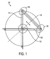
- Figure 1 depicts a Double V beam path of the present embodiment.
- the two V-shaped path's i.e., Double V or DV
- 110 and 120 may be oriented at 90 degrees, at 130, in relation to one another.
- the resulting line of flip symmetry 140
- the resulting line of flip symmetry may bisect the azimuthal angle between the fold mirrors (150). Any disk surface error having odd symmetry about this line may cancel between passes (e.g., y astigmatism, x coma, x trefoil, y tetrafoil about the y axis).
- This criterion is intended to include but not be limited to Zernike aberrations of any order except those of spherical aberration.
- the azimuthal angle of the disk can be rotated about the disk normal to orient the worst aberration(s) to this line of symmetry.
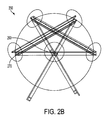
- Figure 2A depicts a triple V beam path 200 with hexagonal symmetry in an implementation. Three and higher-pass geometries, like those shown in Figure 2A , can be used to cancel higher-order aberrations.
- three beam crossings may occur at 210.
- Figure 2B depicts a triple V beam path 250 in a different layout configuration. In Figure 2B , three beam crossings may occur at 260 and an example V arrangement may be located at 270. The number of passes may be physically limited by the dimensions of the beam and reflectors. Similarly, multiple V beam path combinations may be provided in view of available physical size and limitations.
- Figure 3 depicts a Double-V assembly 300.
- a DV mount is depicted at 305 and a pair of dielectric-coated fold mirrors 310 are shown as positioned in relation to the disk 320 and a beam opening at 330.
- Figure 4 depicts a Double-V (DV) assembly 400 with a beam-path conditioning head 440.
- the beam path 420 within the DV assembly in an implementation, may be conditioned with a longitudinal flow of clean, dry air at 430. Air flow may be confined by beam tubes cut into the DV fixture and into beam-path conditioning (BPC) head 440, as shown in Figure 4 .
- BPC beam-path conditioning
- Alternative methods e.g., substituting for air: inert gas purge, vacuum, etc.
- the physical size of the DV, and hence the round-trip optical path length between reflections from the disk may be determined largely by the method of BPC employed.
- the DV mount at 410 is also depicted.
- Figure 5 depicts a typical resonator layout 500 using Double-V assemblies 510, 520, 530 with each gain disk.
- the resonator may utilize a DV assembly 510, 520, 530 for each disk 515, 525, 535 and real relay imaging between disks 540, 550 to maintain an adequately high Fresnel number.
- a larger number of disks can be incorporated into the resonator for power scaling by repeating the pattern where the "dots" on the Figure indicate.
- a wave-optics simulation of a four disk, Yb:YAG unstable resonator is set forth in Figure 6 , where Zernike aberrations (up to term 24) with odd symmetry about the DV flip-line were introduced for each disk surface.
- the total RMS error on a round-trip was 0.03 waves at 1 ⁇ m, and the magnification of the resonator was approximately 1.25 X.
- the disk rotated optimally, at 610 and 620 it is apparent that the aberrations cancel exactly, leaving a uniform intensity and phase profile intra-cavity. Without the DV symmetry, however, the intra-cavity mode builds up intensity and phase distortions that scale with the amplitude of the aberrations as is apparent in 630 and 640.
- the angle of incidence (AOI) for DV fold mirrors may be less than 50 degree and greater than 30 degrees. In a further implementation, an AOI of 42 degrees may be used.
- Standard multilayer high-reflectance (HR) coatings typically may have a small difference in reflectance between the polarizations (i.e., 99.9% p-polarization versus 99.99% for s-polarization) at large angles, and a small differential phase shift.
- HR high-reflectance
- the difference in reflectance is large enough to promote a linearly polarized output beam in a resonator, provided thermal stress-birefringence in the disk is low. Therefore, the present embodiment also provides for polarization beam-combining of two lasers.
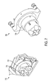
- Figure 7 depicts a Double-V assembly 710, 750 which has been tested.
- the tested assembly included high surface quality mirrors 715 with very high reflectance and low-loss dielectric coatings which were attached to the DV fixture 720, 760 using a low shear stress adhesive, although mechanical means may also be employed to locate the reflectors.
- Figure 8 depicts polarization extinction of the laser output versus pump power 800 for the present embodiment in an implementation. As is apparent in Figure 8 , polarization extinction is generally high and independent of pump power along 810.
- the wavefront cancellation properties of the DV assembly discussed previously were independently tested by introducing a collimated 1 ⁇ m wavelength beam into the device with a surrogate laser disk located in the correct plane.
- the "disk” was a thin HR coated optic with approximately 1 wave PV of astigmatism and a radius of curvature of about 20m concave. Other aberrations were present in smaller amplitudes. Due to the optic's focus and astigmatism, the beam came to x and y foci at different planes after the DV. By rotating the azimuthal angle of the surrogate disk such that the astigmatism was predominantly Zernike y-astig relative to DV, the astigmatism was removed and a focused spot resulted as is shown in Figure 9.
- Figure 9 shows a focused spot at 910 with azimuthal angle of surrogate disk set to cancel astigmatism of the present embodiment.
- the present embodiment has a variety of uses in a diversity of fields including those of: a technology enabler at the weapon-class of solid state technology; provision for high reliability, high efficiency solid state lasers in the weapon-power class; weapons-class laser devices; and related solid-state devices and assemblies.
- the present embodiment provide significant benefits to the field including those of double passing a disk in a compact fashion, and the ability to cancel aberrations on the disks in many instances. Additionally, the present embodiment may be implemented with minimal impact to any thin disk laser assembly to the overall resonator layout.
Landscapes
- Physics & Mathematics (AREA)
- Electromagnetism (AREA)
- Engineering & Computer Science (AREA)
- Plasma & Fusion (AREA)
- Optics & Photonics (AREA)
- Chemical & Material Sciences (AREA)
- Crystallography & Structural Chemistry (AREA)
- Optical Elements Other Than Lenses (AREA)
- Lasers (AREA)
Applications Claiming Priority (1)
| Application Number | Priority Date | Filing Date | Title |
|---|---|---|---|
| US11/847,876 US7826513B2 (en) | 2007-08-30 | 2007-08-30 | Re-entrant structure for thin disk resonators |
Publications (3)
| Publication Number | Publication Date |
|---|---|
| EP2031712A2 true EP2031712A2 (fr) | 2009-03-04 |
| EP2031712A3 EP2031712A3 (fr) | 2011-08-17 |
| EP2031712B1 EP2031712B1 (fr) | 2018-04-18 |
Family
ID=40202074
Family Applications (1)
| Application Number | Title | Priority Date | Filing Date |
|---|---|---|---|
| EP08252770.6A Active EP2031712B1 (fr) | 2007-08-30 | 2008-08-21 | Minimisation des erreurs de front d'onde avec résonateurs lasers à disque mince |
Country Status (2)
| Country | Link |
|---|---|
| US (1) | US7826513B2 (fr) |
| EP (1) | EP2031712B1 (fr) |
Cited By (6)
| Publication number | Priority date | Publication date | Assignee | Title |
|---|---|---|---|---|
| DE102009020768A1 (de) * | 2009-04-30 | 2010-11-11 | Deutsches Zentrum für Luft- und Raumfahrt e.V. | Laserverstärkersystem |
| WO2013003239A1 (fr) * | 2011-06-30 | 2013-01-03 | Coherent, Inc. | Laser à semiconducteur à pompage optique avec verrouillage de modes |
| WO2013152447A3 (fr) * | 2012-04-11 | 2013-11-28 | Time-Bandwidth Products Ag | Laser semi-conducteur pulsé |
| WO2014076694A1 (fr) * | 2012-11-15 | 2014-05-22 | Rafael Advanced Defense Systems Ltd. | Laser haute puissance |
| WO2018019674A1 (fr) * | 2016-07-25 | 2018-02-01 | Trumpf Laser Gmbh | Agencement optique présentant un moyen en forme de disque activé par laser |
| US9985157B2 (en) | 2012-12-07 | 2018-05-29 | Deutsches Zentrum fuer Luft— und Raumfahrt e.V. | Optical energy transmission system |
Families Citing this family (7)
| Publication number | Priority date | Publication date | Assignee | Title |
|---|---|---|---|---|
| KR20100101526A (ko) * | 2009-03-09 | 2010-09-17 | 삼성전자주식회사 | 스트로보 박막 화학 분석 장치 및 이를 이용한 분석 방법 |
| US8379680B1 (en) | 2009-08-10 | 2013-02-19 | The Boeing Company | Direct cooling of thin disk lasers |
| US8605355B2 (en) | 2009-11-24 | 2013-12-10 | Applied Energetics | Off axis walk off multi-pass amplifiers |
| US9500855B2 (en) | 2012-06-04 | 2016-11-22 | The Boeing Company | Modal corrector mirror with compliant actuation for optical aberrations |
| US9166356B2 (en) | 2013-10-17 | 2015-10-20 | The Boeing Company | Unstable imaging resonator |
| DE102016119443B4 (de) | 2016-02-19 | 2023-01-26 | Deutsches Zentrum für Luft- und Raumfahrt e.V. | Multipass-Laserverstärkungssystem und Verfahren zur Korrektur eines unsymmetrischen, transversalen Laserstrahldruckprofils in einem ein laseraktives Medium aufweisenden Festkörper |
| EP4092847A1 (fr) * | 2021-05-18 | 2022-11-23 | Deutsches Elektronen-Synchrotron DESY | Appareil amplificateur à laser et procédé d'amplification d'impulsions laser |
Citations (1)
| Publication number | Priority date | Publication date | Assignee | Title |
|---|---|---|---|---|
| US20070116081A1 (en) | 2005-11-22 | 2007-05-24 | The Boeing Company | Solid-state laser and multi-pass resonator |
Family Cites Families (13)
| Publication number | Priority date | Publication date | Assignee | Title |
|---|---|---|---|---|
| DE3937370A1 (de) * | 1989-11-09 | 1991-05-16 | Otto Bihler | Laser |
| US5553088A (en) * | 1993-07-02 | 1996-09-03 | Deutsche Forschungsanstalt Fuer Luft- Und Raumfahrt E.V. | Laser amplifying system |
| US5757839A (en) * | 1996-10-08 | 1998-05-26 | The Regents Of The University Of Michigan | Optical pumping method and apparatus |
| US6834064B1 (en) * | 1999-12-08 | 2004-12-21 | Time-Bandwidth Products Ag | Mode-locked thin-disk laser |
| DE10005194A1 (de) | 2000-02-05 | 2001-08-16 | Univ Stuttgart Strahlwerkzeuge | Laserverstärkersystem |
| US6542524B2 (en) * | 2000-03-03 | 2003-04-01 | Charles Miyake | Multiwavelength laser for illumination of photo-dynamic therapy drugs |
| DE10054289A1 (de) * | 2000-11-02 | 2002-02-28 | Rofin Sinar Laser Gmbh | Festkörperlaser mit einem resonatorexternen Laserverstärker |
| US6798813B2 (en) * | 2001-07-09 | 2004-09-28 | Coherent, Inc. | Closed-loop purging system for laser |
| DE10140254A1 (de) | 2001-08-09 | 2003-03-06 | Trumpf Laser Gmbh & Co Kg | Laserverstärkersystem |
| US7006283B2 (en) * | 2002-01-15 | 2006-02-28 | Jds Uniphase Corporation | Three-dimensional optical amplifier structure |
| GB0215847D0 (en) * | 2002-07-09 | 2002-08-14 | Imp College Innovations Ltd | Optical amplifying device |
| US7593447B2 (en) * | 2004-07-12 | 2009-09-22 | Santanu Basu | Rotary disk laser module |
| JP4803176B2 (ja) * | 2005-06-02 | 2011-10-26 | 三菱電機株式会社 | 固体レーザ装置 |
-
2007
- 2007-08-30 US US11/847,876 patent/US7826513B2/en active Active
-
2008
- 2008-08-21 EP EP08252770.6A patent/EP2031712B1/fr active Active
Patent Citations (1)
| Publication number | Priority date | Publication date | Assignee | Title |
|---|---|---|---|---|
| US20070116081A1 (en) | 2005-11-22 | 2007-05-24 | The Boeing Company | Solid-state laser and multi-pass resonator |
Cited By (16)
| Publication number | Priority date | Publication date | Assignee | Title |
|---|---|---|---|---|
| CN102414940B (zh) * | 2009-04-30 | 2015-11-25 | 德国航空航天中心 | 激光放大器系统 |
| WO2010145878A1 (fr) * | 2009-04-30 | 2010-12-23 | DEUTSCHES ZENTRUM FüR LUFT-UND RAUMFAHRT E.V. | Système d'amplificateur laser |
| CN102414940A (zh) * | 2009-04-30 | 2012-04-11 | 德国航空航天中心 | 激光放大器系统 |
| DE102009020768A1 (de) * | 2009-04-30 | 2010-11-11 | Deutsches Zentrum für Luft- und Raumfahrt e.V. | Laserverstärkersystem |
| US8599896B2 (en) | 2009-04-30 | 2013-12-03 | Deutsches Zentrum Fuer Luft- Und Raumfahrt E.V. | Laser amplifier system |
| WO2013003239A1 (fr) * | 2011-06-30 | 2013-01-03 | Coherent, Inc. | Laser à semiconducteur à pompage optique avec verrouillage de modes |
| US9236708B2 (en) | 2011-06-30 | 2016-01-12 | Coherent, Inc. | Mode-locked optically pumped semiconductor laser |
| US8774238B2 (en) | 2011-06-30 | 2014-07-08 | Coherent, Inc. | Mode-locked optically pumped semiconductor laser |
| WO2013152447A3 (fr) * | 2012-04-11 | 2013-11-28 | Time-Bandwidth Products Ag | Laser semi-conducteur pulsé |
| WO2014076694A1 (fr) * | 2012-11-15 | 2014-05-22 | Rafael Advanced Defense Systems Ltd. | Laser haute puissance |
| US9985157B2 (en) | 2012-12-07 | 2018-05-29 | Deutsches Zentrum fuer Luft— und Raumfahrt e.V. | Optical energy transmission system |
| WO2018019674A1 (fr) * | 2016-07-25 | 2018-02-01 | Trumpf Laser Gmbh | Agencement optique présentant un moyen en forme de disque activé par laser |
| CN109478762A (zh) * | 2016-07-25 | 2019-03-15 | 通快激光有限责任公司 | 具有盘形激光活性介质的光学组件 |
| KR20190032410A (ko) * | 2016-07-25 | 2019-03-27 | 트룸프 레이저 게엠베하 | 디스크 형상의 레이저 활성 매체를 갖는 광학 장치 |
| CN109478762B (zh) * | 2016-07-25 | 2021-08-06 | 通快激光有限责任公司 | 具有盘形激光活性介质的光学组件 |
| US11271357B2 (en) | 2016-07-25 | 2022-03-08 | Trumpf Laser Gmbh | Optical arrangements with disk-shaped laser-active mediums |
Also Published As
| Publication number | Publication date |
|---|---|
| EP2031712B1 (fr) | 2018-04-18 |
| US20090059991A1 (en) | 2009-03-05 |
| US7826513B2 (en) | 2010-11-02 |
| EP2031712A3 (fr) | 2011-08-17 |
Similar Documents
| Publication | Publication Date | Title |
|---|---|---|
| US7826513B2 (en) | Re-entrant structure for thin disk resonators | |
| US5504763A (en) | System for minimizing the depolarization of a laser beam due to thermally induced birefringence | |
| US5023886A (en) | High power laser with focusing mirror sets | |
| EP1687875B1 (fr) | Laser a plaque a qualite de faisceau amelioree et homogeneisee | |
| KR20100135772A (ko) | 다중-패스 광 전력 증폭기 | |
| WO1995021477A1 (fr) | Laser pompe a diode dont le cristal presente une lentille thermique puissante | |
| US20100226396A1 (en) | Optical Arrangement For Pumping Solid-State Lasers | |
| EP0845165A1 (fr) | Laser confocal a concentrique pompe par une diode | |
| US5907570A (en) | Diode pumped laser using gain mediums with strong thermal focussing | |
| US5577060A (en) | Diode pumped laser using crystals with strong thermal focussing | |
| US20050220164A1 (en) | Laser oscillator | |
| JP2548887B2 (ja) | 自己整列空洞内ラマンレ−ザ | |
| US20100027572A1 (en) | Unstable disk resonator | |
| JP2001077449A (ja) | モード同期固体レーザ | |
| EP1520326B1 (fr) | Dispositif d'amplification optique | |
| US6678308B1 (en) | Laser resonator system using offner relay | |
| CN110380327B (zh) | 一种光束近场强度分布自匀化高能激光器 | |
| US20170310073A1 (en) | Optical Module, Laser Amplifier System, Method and Use | |
| Gobbi et al. | Stable telescopic resonators, unstable resonators and new cavity designs applied to high energy laser engineering | |
| HODGSON | Beam Quality and Efficiency of Annular Gain Lasers | |
| Beedell et al. | Performance of a deformable mirror in a high-energy Nd: YAG laser | |
| Spalding | Characteristics of Laser beams for machining | |
| Chen et al. | Compact thin-disk multipass amplifier tolerant of strong disk thermal distortions | |
| Morin et al. | Stable resonators with a graded reflectivity output coupler | |
| Rabczuk | Resonator for a 2.5-kW CO2 transverse flow laser |
Legal Events
| Date | Code | Title | Description |
|---|---|---|---|
| PUAI | Public reference made under article 153(3) epc to a published international application that has entered the european phase |
Free format text: ORIGINAL CODE: 0009012 |
|
| 17P | Request for examination filed |
Effective date: 20080901 |
|
| AK | Designated contracting states |
Kind code of ref document: A2 Designated state(s): AT BE BG CH CY CZ DE DK EE ES FI FR GB GR HR HU IE IS IT LI LT LU LV MC MT NL NO PL PT RO SE SI SK TR |
|
| AX | Request for extension of the european patent |
Extension state: AL BA MK RS |
|
| PUAL | Search report despatched |
Free format text: ORIGINAL CODE: 0009013 |
|
| AK | Designated contracting states |
Kind code of ref document: A3 Designated state(s): AT BE BG CH CY CZ DE DK EE ES FI FR GB GR HR HU IE IS IT LI LT LU LV MC MT NL NO PL PT RO SE SI SK TR |
|
| AX | Request for extension of the european patent |
Extension state: AL BA MK RS |
|
| RIC1 | Information provided on ipc code assigned before grant |
Ipc: H01S 3/06 20060101AFI20110711BHEP Ipc: H01S 3/08 20060101ALN20110711BHEP Ipc: H01S 3/081 20060101ALN20110711BHEP Ipc: H01S 3/07 20060101ALI20110711BHEP |
|
| AKX | Designation fees paid |
Designated state(s): AT BE BG CH CY CZ DE DK EE ES FI FR GB GR HR HU IE IS IT LI LT LU LV MC MT NL NO PL PT RO SE SI SK TR |
|
| 17Q | First examination report despatched |
Effective date: 20120705 |
|
| GRAP | Despatch of communication of intention to grant a patent |
Free format text: ORIGINAL CODE: EPIDOSNIGR1 |
|
| RIC1 | Information provided on ipc code assigned before grant |
Ipc: H01S 3/06 20060101AFI20170315BHEP Ipc: H01S 3/07 20060101ALI20170315BHEP Ipc: H01S 3/102 20060101ALN20170315BHEP Ipc: H01S 3/081 20060101ALN20170315BHEP Ipc: H01S 3/02 20060101ALN20170315BHEP Ipc: H01S 3/10 20060101ALN20170315BHEP Ipc: H01S 3/08 20060101ALN20170315BHEP |
|
| INTG | Intention to grant announced |
Effective date: 20170413 |
|
| RIC1 | Information provided on ipc code assigned before grant |
Ipc: H01S 3/06 20060101AFI20170403BHEP Ipc: H01S 3/10 20060101ALN20170403BHEP Ipc: H01S 3/08 20060101ALN20170403BHEP Ipc: H01S 3/102 20060101ALN20170403BHEP Ipc: H01S 3/081 20060101ALN20170403BHEP Ipc: H01S 3/02 20060101ALN20170403BHEP Ipc: H01S 3/07 20060101ALI20170403BHEP |
|
| GRAJ | Information related to disapproval of communication of intention to grant by the applicant or resumption of examination proceedings by the epo deleted |
Free format text: ORIGINAL CODE: EPIDOSDIGR1 |
|
| INTC | Intention to grant announced (deleted) | ||
| RIC1 | Information provided on ipc code assigned before grant |
Ipc: H01S 3/07 20060101ALI20170912BHEP Ipc: H01S 3/02 20060101ALN20170912BHEP Ipc: H01S 3/06 20060101AFI20170912BHEP Ipc: H01S 3/081 20060101ALN20170912BHEP Ipc: H01S 3/102 20060101ALN20170912BHEP Ipc: H01S 3/10 20060101ALN20170912BHEP Ipc: H01S 3/08 20060101ALN20170912BHEP |
|
| GRAP | Despatch of communication of intention to grant a patent |
Free format text: ORIGINAL CODE: EPIDOSNIGR1 |
|
| INTG | Intention to grant announced |
Effective date: 20171027 |
|
| GRAS | Grant fee paid |
Free format text: ORIGINAL CODE: EPIDOSNIGR3 |
|
| GRAA | (expected) grant |
Free format text: ORIGINAL CODE: 0009210 |
|
| AK | Designated contracting states |
Kind code of ref document: B1 Designated state(s): AT BE BG CH CY CZ DE DK EE ES FI FR GB GR HR HU IE IS IT LI LT LU LV MC MT NL NO PL PT RO SE SI SK TR |
|
| REG | Reference to a national code |
Ref country code: GB Ref legal event code: FG4D |
|
| REG | Reference to a national code |
Ref country code: CH Ref legal event code: EP |
|
| REG | Reference to a national code |
Ref country code: AT Ref legal event code: REF Ref document number: 991434 Country of ref document: AT Kind code of ref document: T Effective date: 20180515 |
|
| REG | Reference to a national code |
Ref country code: IE Ref legal event code: FG4D |
|
| REG | Reference to a national code |
Ref country code: DE Ref legal event code: R096 Ref document number: 602008054872 Country of ref document: DE |
|
| REG | Reference to a national code |
Ref country code: NL Ref legal event code: MP Effective date: 20180418 |
|
| REG | Reference to a national code |
Ref country code: FR Ref legal event code: PLFP Year of fee payment: 11 |
|
| REG | Reference to a national code |
Ref country code: LT Ref legal event code: MG4D |
|
| PG25 | Lapsed in a contracting state [announced via postgrant information from national office to epo] |
Ref country code: NL Free format text: LAPSE BECAUSE OF FAILURE TO SUBMIT A TRANSLATION OF THE DESCRIPTION OR TO PAY THE FEE WITHIN THE PRESCRIBED TIME-LIMIT Effective date: 20180418 |
|
| PG25 | Lapsed in a contracting state [announced via postgrant information from national office to epo] |
Ref country code: FI Free format text: LAPSE BECAUSE OF FAILURE TO SUBMIT A TRANSLATION OF THE DESCRIPTION OR TO PAY THE FEE WITHIN THE PRESCRIBED TIME-LIMIT Effective date: 20180418 Ref country code: NO Free format text: LAPSE BECAUSE OF FAILURE TO SUBMIT A TRANSLATION OF THE DESCRIPTION OR TO PAY THE FEE WITHIN THE PRESCRIBED TIME-LIMIT Effective date: 20180718 Ref country code: LT Free format text: LAPSE BECAUSE OF FAILURE TO SUBMIT A TRANSLATION OF THE DESCRIPTION OR TO PAY THE FEE WITHIN THE PRESCRIBED TIME-LIMIT Effective date: 20180418 Ref country code: PL Free format text: LAPSE BECAUSE OF FAILURE TO SUBMIT A TRANSLATION OF THE DESCRIPTION OR TO PAY THE FEE WITHIN THE PRESCRIBED TIME-LIMIT Effective date: 20180418 Ref country code: ES Free format text: LAPSE BECAUSE OF FAILURE TO SUBMIT A TRANSLATION OF THE DESCRIPTION OR TO PAY THE FEE WITHIN THE PRESCRIBED TIME-LIMIT Effective date: 20180418 Ref country code: SE Free format text: LAPSE BECAUSE OF FAILURE TO SUBMIT A TRANSLATION OF THE DESCRIPTION OR TO PAY THE FEE WITHIN THE PRESCRIBED TIME-LIMIT Effective date: 20180418 Ref country code: BG Free format text: LAPSE BECAUSE OF FAILURE TO SUBMIT A TRANSLATION OF THE DESCRIPTION OR TO PAY THE FEE WITHIN THE PRESCRIBED TIME-LIMIT Effective date: 20180718 |
|
| PG25 | Lapsed in a contracting state [announced via postgrant information from national office to epo] |
Ref country code: LV Free format text: LAPSE BECAUSE OF FAILURE TO SUBMIT A TRANSLATION OF THE DESCRIPTION OR TO PAY THE FEE WITHIN THE PRESCRIBED TIME-LIMIT Effective date: 20180418 Ref country code: GR Free format text: LAPSE BECAUSE OF FAILURE TO SUBMIT A TRANSLATION OF THE DESCRIPTION OR TO PAY THE FEE WITHIN THE PRESCRIBED TIME-LIMIT Effective date: 20180719 Ref country code: HR Free format text: LAPSE BECAUSE OF FAILURE TO SUBMIT A TRANSLATION OF THE DESCRIPTION OR TO PAY THE FEE WITHIN THE PRESCRIBED TIME-LIMIT Effective date: 20180418 |
|
| REG | Reference to a national code |
Ref country code: AT Ref legal event code: MK05 Ref document number: 991434 Country of ref document: AT Kind code of ref document: T Effective date: 20180418 |
|
| PG25 | Lapsed in a contracting state [announced via postgrant information from national office to epo] |
Ref country code: PT Free format text: LAPSE BECAUSE OF FAILURE TO SUBMIT A TRANSLATION OF THE DESCRIPTION OR TO PAY THE FEE WITHIN THE PRESCRIBED TIME-LIMIT Effective date: 20180820 |
|
| REG | Reference to a national code |
Ref country code: DE Ref legal event code: R097 Ref document number: 602008054872 Country of ref document: DE |
|
| PG25 | Lapsed in a contracting state [announced via postgrant information from national office to epo] |
Ref country code: EE Free format text: LAPSE BECAUSE OF FAILURE TO SUBMIT A TRANSLATION OF THE DESCRIPTION OR TO PAY THE FEE WITHIN THE PRESCRIBED TIME-LIMIT Effective date: 20180418 Ref country code: DK Free format text: LAPSE BECAUSE OF FAILURE TO SUBMIT A TRANSLATION OF THE DESCRIPTION OR TO PAY THE FEE WITHIN THE PRESCRIBED TIME-LIMIT Effective date: 20180418 Ref country code: AT Free format text: LAPSE BECAUSE OF FAILURE TO SUBMIT A TRANSLATION OF THE DESCRIPTION OR TO PAY THE FEE WITHIN THE PRESCRIBED TIME-LIMIT Effective date: 20180418 Ref country code: SK Free format text: LAPSE BECAUSE OF FAILURE TO SUBMIT A TRANSLATION OF THE DESCRIPTION OR TO PAY THE FEE WITHIN THE PRESCRIBED TIME-LIMIT Effective date: 20180418 Ref country code: CZ Free format text: LAPSE BECAUSE OF FAILURE TO SUBMIT A TRANSLATION OF THE DESCRIPTION OR TO PAY THE FEE WITHIN THE PRESCRIBED TIME-LIMIT Effective date: 20180418 Ref country code: RO Free format text: LAPSE BECAUSE OF FAILURE TO SUBMIT A TRANSLATION OF THE DESCRIPTION OR TO PAY THE FEE WITHIN THE PRESCRIBED TIME-LIMIT Effective date: 20180418 |
|
| PLBE | No opposition filed within time limit |
Free format text: ORIGINAL CODE: 0009261 |
|
| STAA | Information on the status of an ep patent application or granted ep patent |
Free format text: STATUS: NO OPPOSITION FILED WITHIN TIME LIMIT |
|
| PG25 | Lapsed in a contracting state [announced via postgrant information from national office to epo] |
Ref country code: IT Free format text: LAPSE BECAUSE OF FAILURE TO SUBMIT A TRANSLATION OF THE DESCRIPTION OR TO PAY THE FEE WITHIN THE PRESCRIBED TIME-LIMIT Effective date: 20180418 |
|
| 26N | No opposition filed |
Effective date: 20190121 |
|
| PG25 | Lapsed in a contracting state [announced via postgrant information from national office to epo] |
Ref country code: MC Free format text: LAPSE BECAUSE OF FAILURE TO SUBMIT A TRANSLATION OF THE DESCRIPTION OR TO PAY THE FEE WITHIN THE PRESCRIBED TIME-LIMIT Effective date: 20180418 |
|
| REG | Reference to a national code |
Ref country code: CH Ref legal event code: PL |
|
| PG25 | Lapsed in a contracting state [announced via postgrant information from national office to epo] |
Ref country code: LI Free format text: LAPSE BECAUSE OF NON-PAYMENT OF DUE FEES Effective date: 20180831 Ref country code: CH Free format text: LAPSE BECAUSE OF NON-PAYMENT OF DUE FEES Effective date: 20180831 Ref country code: LU Free format text: LAPSE BECAUSE OF NON-PAYMENT OF DUE FEES Effective date: 20180821 |
|
| REG | Reference to a national code |
Ref country code: BE Ref legal event code: MM Effective date: 20180831 |
|
| PG25 | Lapsed in a contracting state [announced via postgrant information from national office to epo] |
Ref country code: SI Free format text: LAPSE BECAUSE OF FAILURE TO SUBMIT A TRANSLATION OF THE DESCRIPTION OR TO PAY THE FEE WITHIN THE PRESCRIBED TIME-LIMIT Effective date: 20180418 |
|
| PG25 | Lapsed in a contracting state [announced via postgrant information from national office to epo] |
Ref country code: BE Free format text: LAPSE BECAUSE OF NON-PAYMENT OF DUE FEES Effective date: 20180831 |
|
| REG | Reference to a national code |
Ref country code: DE Ref legal event code: R082 Ref document number: 602008054872 Country of ref document: DE Representative=s name: MAIER, LL.M., MICHAEL C., DE Ref country code: DE Ref legal event code: R082 Ref document number: 602008054872 Country of ref document: DE Representative=s name: BOULT WADE TENNANT LLP, DE |
|
| PG25 | Lapsed in a contracting state [announced via postgrant information from national office to epo] |
Ref country code: MT Free format text: LAPSE BECAUSE OF NON-PAYMENT OF DUE FEES Effective date: 20180821 |
|
| REG | Reference to a national code |
Ref country code: DE Ref legal event code: R082 Ref document number: 602008054872 Country of ref document: DE Representative=s name: BOULT WADE TENNANT LLP, DE |
|
| PG25 | Lapsed in a contracting state [announced via postgrant information from national office to epo] |
Ref country code: TR Free format text: LAPSE BECAUSE OF FAILURE TO SUBMIT A TRANSLATION OF THE DESCRIPTION OR TO PAY THE FEE WITHIN THE PRESCRIBED TIME-LIMIT Effective date: 20180418 |
|
| PG25 | Lapsed in a contracting state [announced via postgrant information from national office to epo] |
Ref country code: HU Free format text: LAPSE BECAUSE OF FAILURE TO SUBMIT A TRANSLATION OF THE DESCRIPTION OR TO PAY THE FEE WITHIN THE PRESCRIBED TIME-LIMIT; INVALID AB INITIO Effective date: 20080821 |
|
| PG25 | Lapsed in a contracting state [announced via postgrant information from national office to epo] |
Ref country code: CY Free format text: LAPSE BECAUSE OF FAILURE TO SUBMIT A TRANSLATION OF THE DESCRIPTION OR TO PAY THE FEE WITHIN THE PRESCRIBED TIME-LIMIT Effective date: 20180418 Ref country code: IE Free format text: LAPSE BECAUSE OF NON-PAYMENT OF DUE FEES Effective date: 20180821 |
|
| PG25 | Lapsed in a contracting state [announced via postgrant information from national office to epo] |
Ref country code: IS Free format text: LAPSE BECAUSE OF FAILURE TO SUBMIT A TRANSLATION OF THE DESCRIPTION OR TO PAY THE FEE WITHIN THE PRESCRIBED TIME-LIMIT Effective date: 20180818 |
|
| P01 | Opt-out of the competence of the unified patent court (upc) registered |
Effective date: 20230516 |
|
| PGFP | Annual fee paid to national office [announced via postgrant information from national office to epo] |
Ref country code: DE Payment date: 20250827 Year of fee payment: 18 |
|
| PGFP | Annual fee paid to national office [announced via postgrant information from national office to epo] |
Ref country code: GB Payment date: 20250827 Year of fee payment: 18 |
|
| PGFP | Annual fee paid to national office [announced via postgrant information from national office to epo] |
Ref country code: FR Payment date: 20250825 Year of fee payment: 18 |