EP2031935A2 - Elektrische Induktionserwärmungsvorrichtung mit dadurch fließendem flüssigen Medium - Google Patents
Elektrische Induktionserwärmungsvorrichtung mit dadurch fließendem flüssigen Medium Download PDFInfo
- Publication number
- EP2031935A2 EP2031935A2 EP08163086A EP08163086A EP2031935A2 EP 2031935 A2 EP2031935 A2 EP 2031935A2 EP 08163086 A EP08163086 A EP 08163086A EP 08163086 A EP08163086 A EP 08163086A EP 2031935 A2 EP2031935 A2 EP 2031935A2
- Authority
- EP
- European Patent Office
- Prior art keywords
- gas
- plenum
- solenoidal
- coil
- gas supply
- Prior art date
- Legal status (The legal status is an assumption and is not a legal conclusion. Google has not performed a legal analysis and makes no representation as to the accuracy of the status listed.)
- Withdrawn
Links
- 230000006698 induction Effects 0.000 title claims abstract description 70
- 238000010438 heat treatment Methods 0.000 title claims abstract description 46
- 239000012530 fluid Substances 0.000 title abstract description 9
- 238000000034 method Methods 0.000 claims abstract description 8
- 239000000463 material Substances 0.000 claims description 14
- 230000004907 flux Effects 0.000 claims description 3
- 239000011248 coating agent Substances 0.000 description 6
- 238000000576 coating method Methods 0.000 description 6
- 239000002184 metal Substances 0.000 description 3
- 238000004804 winding Methods 0.000 description 3
- 230000008901 benefit Effects 0.000 description 2
- 239000000383 hazardous chemical Substances 0.000 description 2
- 238000009413 insulation Methods 0.000 description 2
- 230000001105 regulatory effect Effects 0.000 description 2
- 230000015572 biosynthetic process Effects 0.000 description 1
- 230000008859 change Effects 0.000 description 1
- 239000002826 coolant Substances 0.000 description 1
- 238000001816 cooling Methods 0.000 description 1
- 238000000151 deposition Methods 0.000 description 1
- 238000001035 drying Methods 0.000 description 1
- 230000000694 effects Effects 0.000 description 1
- 231100001261 hazardous Toxicity 0.000 description 1
- 238000002955 isolation Methods 0.000 description 1
- 239000007788 liquid Substances 0.000 description 1
- 238000012986 modification Methods 0.000 description 1
- 230000004048 modification Effects 0.000 description 1
- 230000004044 response Effects 0.000 description 1
- 239000007787 solid Substances 0.000 description 1
Images

Classifications
-
- H—ELECTRICITY
- H05—ELECTRIC TECHNIQUES NOT OTHERWISE PROVIDED FOR
- H05B—ELECTRIC HEATING; ELECTRIC LIGHT SOURCES NOT OTHERWISE PROVIDED FOR; CIRCUIT ARRANGEMENTS FOR ELECTRIC LIGHT SOURCES, IN GENERAL
- H05B6/00—Heating by electric, magnetic or electromagnetic fields
- H05B6/02—Induction heating
- H05B6/10—Induction heating apparatus, other than furnaces, for specific applications
- H05B6/101—Induction heating apparatus, other than furnaces, for specific applications for local heating of metal pieces
- H05B6/103—Induction heating apparatus, other than furnaces, for specific applications for local heating of metal pieces multiple metal pieces successively being moved close to the inductor
- H05B6/104—Induction heating apparatus, other than furnaces, for specific applications for local heating of metal pieces multiple metal pieces successively being moved close to the inductor metal pieces being elongated like wires or bands
-
- H—ELECTRICITY
- H05—ELECTRIC TECHNIQUES NOT OTHERWISE PROVIDED FOR
- H05B—ELECTRIC HEATING; ELECTRIC LIGHT SOURCES NOT OTHERWISE PROVIDED FOR; CIRCUIT ARRANGEMENTS FOR ELECTRIC LIGHT SOURCES, IN GENERAL
- H05B6/00—Heating by electric, magnetic or electromagnetic fields
- H05B6/02—Induction heating
- H05B6/36—Coil arrangements
- H05B6/365—Coil arrangements using supplementary conductive or ferromagnetic pieces
Definitions
- the present invention generally relates to an electric induction heating apparatus wherein an enclosed chamber isolates a workpiece from the surrounding environment while the workpiece passes through the chamber and a fluid medium flow is provided in the chamber.
- Electric induction heating apparatus can be provided with an enclosed chamber to isolate an electrically conductive workpiece from the surrounding environment as it moves through the chamber and is inductively heated.
- One reason for such isolation is to contain hazardous materials that may be produced in the heating process.
- the workpiece is a metal strip that has been coated with a liquid coating material prior to entry into the chamber
- inductively heating the strip in the chamber to bond the coating material to the surface of the strip may release hazardous vapors.
- a fluid medium may be introduced into the enclosed chamber, for example, to assist in the drying of the coating material on the surface of the strip, or to extract hazardous materials produced in the heating process from the chamber.
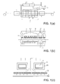
- the workpiece Prior to entry into furnace (3), the workpiece, metal strip (1) passes through coating apparatus (2) wherein a coating material is applied to the surface of the workpiece.
- the furnace comprises a plurality of induction heating zones (7) that are spaced apart by upper hot air supply passages (12) and lower hot air exhaust ports (16).
- Each induction heating zone comprises a solenoidal induction coil (6) (with internal passage for a cooling medium and external thermal insulation) that surrounds the strip as it passes through the zone, and an upper hot air supply passage (12) that supplies hot air between the windings of the solenoidal coil in each heating zone.
- the supplied hot air through air supply passages (12) in each heating zone, and each adjacent hot air supply/exhaust zone passes through baffles (11) onto the upper side of the strip in the furnace to prevent formation of dew from vapors released by the coating material in the furnace, and to prevent solid contaminates from depositing on the upper surface of the strip as it passes through the furnace.
- Upon exit from the furnace the strip passes through a cooling apparatus (4) and is rolled into product coil (5).
- the air handling system comprises air supply pump (13), supply filter (14), supply heat exchanger (15), and exhaust vapor processing apparatus (17).
- Japanese patent publication JP 63-4873 discloses a unidirectional flow of hot air from the upper regions of furnace (3) to the lower regions of the furnace.
- an enclosed electric induction furnace wherein a heated gas is injected into the inlet and outlet of the furnace by supply duct (7) and evacuated via exhaust duct (6) located between adjacent induction heating zones.
- Each heating zone comprises solenoidal induction coil (5) which is physically isolated from the flow of the heated gas and the interior of the enclosed electric induction furnace by gastight walled sections.
- United States Patent No. 5,768,799 discloses a unidirectional flow of a preheated gas from the lower opposing ends of the furnace to the upper central region of the furnace.
- a fluid medium such as a gas
- the present invention is an induction heating apparatus for, and method of, inductively heating a workpiece, such as an electrically conductive strip, moving through a chamber.
- the outer boundary of the chamber is formed from a gas plenum that surrounds a section of the workpiece moving through the chamber.
- At least one induction coil is located in the plenum and positioned around the section of the workpiece in the chamber.
- a plurality of passages is provided through the induction coil. If the coil is a multi-turn solenoidal coil, the passages are formed by openings between one or more turns of the thermally insulated multi-turn induction coil. If the coil is a single turn coil, the passages are formed by openings in the single turn of the coil.
- a fluid medium such as a gas
- a fluid medium can be introduced into the gas supply plenum surrounding the induction coil so that gas flows through the passages in the induction coil can be directed towards the opposing surfaces of the strip.
- the gas is removed from the chamber by a gas exhaust plenum that can be alternatively located adjacent to the gas supply plenum, or around the gas supply plenum.
- FIG. 1(a), FIG. 1(b) and FIG. 1(c) are one example of a prior art electric induction heating apparatus.
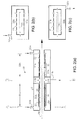
- FIG. 2(a) illustrates in longitudinal cross section one example of the electric induction heating apparatus of the present invention.
- FIG. 2(b) and FIG. 2(c) illustrate in cross section the apparatus in FIG. 3(a) through lines A-A and B-B in FIG. 3(a) , respectively.
- FIG. 3 illustrates in longitudinal cross section another example of the electric induction heating apparatus of the present invention.
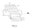
- FIG. 4 is a perspective view of one example of a single turn inductor used in an electric induction heating apparatus of the present invention.
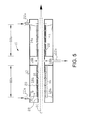
- FIG. 5 illustrates in longitudinal cross section another example of the electric induction heating apparatus of the present invention.
- FIG. 2(a), FIG. 2(b) and FIG. 2(c) one example of induction heating apparatus 10 of the present invention.
- Induction heating apparatus 10 has an outer boundary 12 that forms a gas plenum comprising gas supply regions 14a and gas exhaust regions 14b which are substantially enclosed except for the entry and exit ports for a workpiece, for example, electrically conductive metal strip 90 that passes through the apparatus.
- Outer boundary 12 may be formed from a singular structure or be assembled from parts that are joined together, for example, by flange sections.
- One or more induction heating zones are provided in the apparatus.
- each induction heating zone comprises solenoidal induction coil 16 with thermal insulation 18 surrounding each turn of the coil. Passages 20 are provided between at least some of the adjacent windings of the coil.
- a suitable source of alternating current (ac) is supplied to each coil so that current flowing through the coil establishes a flux field that couples with the strip to inductively heat the strip.
- the ac source may either be a single power supply or multiple power supplies each connected to one of the induction coils. In the non-limiting example of the invention shown in FIG. 2(a), FIG. 2(b) and FIG.
- a fluid medium such as a gas flows through the gas plenum from inlets 22a to outlet passages 20 with the arrows in the figures indicating gas flow.
- Each thermally insulated induction coil is located in the gas plenum so that supply gas flows into the gas plenum and through passages 20.
- evacuation of the supply gas from the gas plenum is via exhaust plenum 14b located between the two induction heating zones, and then through exhaust port 22b, which can be connected to a contaminated gas processing apparatus such as an incinerator.
- each heating zone is formed around a gas supply plenum disposed between a gas exhaust plenum and the plurality of openings, or passages 20, between at least some of the adjacent windings of the induction coil allow the gas, or fluid medium, to be directed towards the opposing surface areas of the sections of the workpiece in the heating zones, as seen, for example, in FIG. 2(b) .
- the gas exhaust regions surround the workpiece so that gas can be exhausted from the heating zone in all directions around the workpiece, as seen, for example, in FIG. 2(c) .
- passages 20 are provided in the top, bottom and opposing sides of the induction coil
- the passages may be provided in the opposing top and bottom regions of the induction coil, or otherwise suitably arranged, to provide a gas flow towards the opposing surfaces of the workpiece.
- exhaust passages 21 into gas exhaust regions 14b of the gas exhaust plenum are shown surrounding all sides of the workpiece, in other examples of the invention, the exhaust passages may be limited to one or more sides of the workpiece. Further in other examples of the invention the exhaust gas plenum may be open to the workpiece moving through the exhaust gas plenum, rather than connected to the workpiece region by discrete exhaust passages 21.
- gas exhaust plenum 14b' may at least partially surround gas supply plenum 14a' and draw gas from the opposing ends of the induction heating apparatus as shown in FIG. 3 with the arrows indicating gas flow.
- the fluid medium is supplied over the opposing surface areas of the section of the workpiece in the heating zone through passages 20 and exhausted at the opposing ends of the gas plenum through the surrounding gas exhaust plenum.
- the multi-turn solenoidal coil in each heating zone can be replaced by a single turn inductor 26, for example, as illustrate in FIG. 4 .
- a suitable source of ac power can be provided to terminals 26a and 26b of the inductor.
- a plurality of passages 28 can be formed in the single turn induction coil as a plurality of holes, or openings, to provide flow paths for the gas from the gas supply plenum towards the opposing surfaces of the workpiece.
- Passages 28 can be provided in the opposing top and bottom sides of the inductor, or otherwise suitably arranged, so that gas flow is directed towards opposing surfaces of the workpiece.
- the single turn inductor can alternatively replace the multi-turn coil in all examples of the invention.
- the rate of gas supply and exhaust can be regulated to change the gas pressure in the chamber from a positive pressure to a negative pressure condition.
- one or more of the passages 20 or 28 can be regulated to control the flow of air over selected portions of the strip in the chamber in each of the heating zones.
- flow damper 30 in FIG. 5 may be used to control flow relative to the passage 20 at the end of the inductor and the other passages 20 through the inductor.
- Damper position "a" (diagrammatically shown in solid line in FIG. 5 ) directs most of the supply air to the end passage
- damper position "b" (diagrammatically shown in dashed line in FIG. 5 ) directs the supply air more evenly along the length of the heating zone.
- a series of coordinated flow dampers may be used to dynamically control the gas flow through selected groups of passages 20 or 28 in response to changing requirements of the strip moving through the apparatus.
Landscapes
- Physics & Mathematics (AREA)
- Electromagnetism (AREA)
- Engineering & Computer Science (AREA)
- Power Engineering (AREA)
- General Induction Heating (AREA)
Applications Claiming Priority (1)
| Application Number | Priority Date | Filing Date | Title |
|---|---|---|---|
| US96833207P | 2007-08-28 | 2007-08-28 |
Publications (1)
| Publication Number | Publication Date |
|---|---|
| EP2031935A2 true EP2031935A2 (de) | 2009-03-04 |
Family
ID=39865790
Family Applications (1)
| Application Number | Title | Priority Date | Filing Date |
|---|---|---|---|
| EP08163086A Withdrawn EP2031935A2 (de) | 2007-08-28 | 2008-08-27 | Elektrische Induktionserwärmungsvorrichtung mit dadurch fließendem flüssigen Medium |
Country Status (2)
| Country | Link |
|---|---|
| US (1) | US20090057301A1 (de) |
| EP (1) | EP2031935A2 (de) |
Families Citing this family (7)
| Publication number | Priority date | Publication date | Assignee | Title |
|---|---|---|---|---|
| JPWO2011074383A1 (ja) | 2009-12-14 | 2013-04-25 | 新日鐵住金株式会社 | 誘導加熱装置の制御装置、誘導加熱システム及び誘導加熱装置の制御方法 |
| US8512629B2 (en) * | 2010-01-18 | 2013-08-20 | General Electric Company | System and method for annealing alloy steel components |
| RU2518187C2 (ru) * | 2010-02-19 | 2014-06-10 | Ниппон Стил Корпорейшн | Устройство индукционного нагрева с поперечным потоком |
| WO2016035893A1 (ja) * | 2014-09-05 | 2016-03-10 | 新日鐵住金株式会社 | 金属帯板の誘導加熱装置 |
| CN105698525B (zh) * | 2014-11-27 | 2019-07-23 | 宝山钢铁股份有限公司 | 具有分半式平板感应线圈的感应加热炉 |
| FR3107635B1 (fr) * | 2020-02-24 | 2023-06-02 | Fives Celes | Dispositif de chauffage d’un produit par induction a flux transverse |
| EP4271129A1 (de) * | 2022-04-29 | 2023-11-01 | SMS Elotherm GmbH | Vorrichtung zur induktiven erwärmung zumindest eines werkstücks sowie verfahren zur induktiven erwärmung zumindest eines werkstücks |
Citations (2)
| Publication number | Priority date | Publication date | Assignee | Title |
|---|---|---|---|---|
| JPS634873A (ja) | 1986-06-25 | 1988-01-09 | Kawatetsu Kohan Kk | 金属ストリツプの連続塗覆装ラインにおける誘導加熱炉 |
| US5768799A (en) | 1995-05-23 | 1998-06-23 | Stein Heurtey | Process and apparatus for coating metal sheets |
Family Cites Families (1)
| Publication number | Priority date | Publication date | Assignee | Title |
|---|---|---|---|---|
| US20040081756A1 (en) * | 2001-12-03 | 2004-04-29 | Coots Timothy D. | Workpiece coating apparatus |
-
2008
- 2008-08-26 US US12/198,275 patent/US20090057301A1/en not_active Abandoned
- 2008-08-27 EP EP08163086A patent/EP2031935A2/de not_active Withdrawn
Patent Citations (2)
| Publication number | Priority date | Publication date | Assignee | Title |
|---|---|---|---|---|
| JPS634873A (ja) | 1986-06-25 | 1988-01-09 | Kawatetsu Kohan Kk | 金属ストリツプの連続塗覆装ラインにおける誘導加熱炉 |
| US5768799A (en) | 1995-05-23 | 1998-06-23 | Stein Heurtey | Process and apparatus for coating metal sheets |
Also Published As
| Publication number | Publication date |
|---|---|
| US20090057301A1 (en) | 2009-03-05 |
Similar Documents
| Publication | Publication Date | Title |
|---|---|---|
| EP2031935A2 (de) | Elektrische Induktionserwärmungsvorrichtung mit dadurch fließendem flüssigen Medium | |
| CA1185663A (en) | Inductive heater | |
| KR20050081161A (ko) | 과열 증기 발생장치 | |
| KR102574745B1 (ko) | 복사식 버너 | |
| JP2021522643A (ja) | 熱的に絶縁された誘導加熱モジュールおよび関連する方法 | |
| US4849598A (en) | Method of and apparatus for baking coating layer utilizing electrical induction and eddy currents | |
| US20240237159A9 (en) | Systems and methods for magnetic heat induction and exchange to mobile streams of matter | |
| US20200299794A1 (en) | Apparatus and Methods for Heating and Quenching Tubular Members | |
| EP2659022B1 (de) | Trockenbeschichtungsvorrichtung | |
| CN104132454A (zh) | 热气体产生装置 | |
| JP2023543086A5 (de) | ||
| EP2577201B1 (de) | Gasversiegelter tunnelofen mit elektrischer induktion | |
| JP7557622B2 (ja) | 金属ストリップを連続的に熱処理するための垂直炉 | |
| CN214501265U (zh) | 电磁加热式催化器 | |
| JP7437136B2 (ja) | スマートサセプタ誘導加熱装置のための加熱回路レイアウト | |
| JP3532761B2 (ja) | 半導体製造装置用流体加熱装置 | |
| JPH0992449A (ja) | 誘導加熱器 | |
| KR102820319B1 (ko) | 궐련 바닥 가열 기능을 갖는 에어로졸 발생장치 | |
| KR20250044253A (ko) | 유도 가열 저감 장치용 워크 코일 | |
| JP7742080B2 (ja) | 誘導加熱装置 | |
| DE102009046410A1 (de) | Vorrichtung zum induktiven Heizen von Werkstücken mit Kühlung | |
| JP2003151736A (ja) | 電磁誘導による流体加熱装置 | |
| JP2020094537A (ja) | 内燃機関の排気浄化装置 | |
| JPS6074418A (ja) | 積層鉄心の誘導加熱方法および装置 | |
| JP2020094538A (ja) | 内燃機関の排気浄化装置 |
Legal Events
| Date | Code | Title | Description |
|---|---|---|---|
| PUAI | Public reference made under article 153(3) epc to a published international application that has entered the european phase |
Free format text: ORIGINAL CODE: 0009012 |
|
| AK | Designated contracting states |
Kind code of ref document: A2 Designated state(s): AT BE BG CH CY CZ DE DK EE ES FI FR GB GR HR HU IE IS IT LI LT LU LV MC MT NL NO PL PT RO SE SI SK TR |
|
| AX | Request for extension of the european patent |
Extension state: AL BA MK RS |
|
| STAA | Information on the status of an ep patent application or granted ep patent |
Free format text: STATUS: THE APPLICATION HAS BEEN WITHDRAWN |
|
| 18W | Application withdrawn |
Effective date: 20120801 |