EP2032305B1 - Gurtbefestigungssystem - Google Patents
Gurtbefestigungssystem Download PDFInfo
- Publication number
- EP2032305B1 EP2032305B1 EP07795629.0A EP07795629A EP2032305B1 EP 2032305 B1 EP2032305 B1 EP 2032305B1 EP 07795629 A EP07795629 A EP 07795629A EP 2032305 B1 EP2032305 B1 EP 2032305B1
- Authority
- EP
- European Patent Office
- Prior art keywords
- belt
- plate
- raised
- anvil
- base
- Prior art date
- Legal status (The legal status is an assumption and is not a legal conclusion. Google has not performed a legal analysis and makes no representation as to the accuracy of the status listed.)
- Active
Links
Images





Classifications
-
- F—MECHANICAL ENGINEERING; LIGHTING; HEATING; WEAPONS; BLASTING
- F16—ENGINEERING ELEMENTS AND UNITS; GENERAL MEASURES FOR PRODUCING AND MAINTAINING EFFECTIVE FUNCTIONING OF MACHINES OR INSTALLATIONS; THERMAL INSULATION IN GENERAL
- F16G—BELTS, CABLES, OR ROPES, PREDOMINANTLY USED FOR DRIVING PURPOSES; CHAINS; FITTINGS PREDOMINANTLY USED THEREFOR
- F16G3/00—Belt fastenings, e.g. for conveyor belts
- F16G3/02—Belt fastenings, e.g. for conveyor belts with series of eyes or the like, interposed and linked by a pin to form a hinge
- F16G3/04—Belt fastenings, e.g. for conveyor belts with series of eyes or the like, interposed and linked by a pin to form a hinge in which the ends of separate U-shaped or like eyes are attached to the belt by parts penetrating into it
-
- F—MECHANICAL ENGINEERING; LIGHTING; HEATING; WEAPONS; BLASTING
- F16—ENGINEERING ELEMENTS AND UNITS; GENERAL MEASURES FOR PRODUCING AND MAINTAINING EFFECTIVE FUNCTIONING OF MACHINES OR INSTALLATIONS; THERMAL INSULATION IN GENERAL
- F16G—BELTS, CABLES, OR ROPES, PREDOMINANTLY USED FOR DRIVING PURPOSES; CHAINS; FITTINGS PREDOMINANTLY USED THEREFOR
- F16G3/00—Belt fastenings, e.g. for conveyor belts
- F16G3/16—Devices or machines for connecting driving-belts or the like
-
- Y—GENERAL TAGGING OF NEW TECHNOLOGICAL DEVELOPMENTS; GENERAL TAGGING OF CROSS-SECTIONAL TECHNOLOGIES SPANNING OVER SEVERAL SECTIONS OF THE IPC; TECHNICAL SUBJECTS COVERED BY FORMER USPC CROSS-REFERENCE ART COLLECTIONS [XRACs] AND DIGESTS
- Y10—TECHNICAL SUBJECTS COVERED BY FORMER USPC
- Y10T—TECHNICAL SUBJECTS COVERED BY FORMER US CLASSIFICATION
- Y10T29/00—Metal working
- Y10T29/53—Means to assemble or disassemble
- Y10T29/53709—Overedge assembling means
- Y10T29/53713—Belt-hook attacher
-
- Y—GENERAL TAGGING OF NEW TECHNOLOGICAL DEVELOPMENTS; GENERAL TAGGING OF CROSS-SECTIONAL TECHNOLOGIES SPANNING OVER SEVERAL SECTIONS OF THE IPC; TECHNICAL SUBJECTS COVERED BY FORMER USPC CROSS-REFERENCE ART COLLECTIONS [XRACs] AND DIGESTS
- Y10—TECHNICAL SUBJECTS COVERED BY FORMER USPC
- Y10T—TECHNICAL SUBJECTS COVERED BY FORMER US CLASSIFICATION
- Y10T29/00—Metal working
- Y10T29/53—Means to assemble or disassemble
- Y10T29/53961—Means to assemble or disassemble with work-holder for assembly
-
- Y—GENERAL TAGGING OF NEW TECHNOLOGICAL DEVELOPMENTS; GENERAL TAGGING OF CROSS-SECTIONAL TECHNOLOGIES SPANNING OVER SEVERAL SECTIONS OF THE IPC; TECHNICAL SUBJECTS COVERED BY FORMER USPC CROSS-REFERENCE ART COLLECTIONS [XRACs] AND DIGESTS
- Y10—TECHNICAL SUBJECTS COVERED BY FORMER USPC
- Y10T—TECHNICAL SUBJECTS COVERED BY FORMER US CLASSIFICATION
- Y10T29/00—Metal working
- Y10T29/53—Means to assemble or disassemble
- Y10T29/53978—Means to assemble or disassemble including means to relatively position plural work parts
-
- Y—GENERAL TAGGING OF NEW TECHNOLOGICAL DEVELOPMENTS; GENERAL TAGGING OF CROSS-SECTIONAL TECHNOLOGIES SPANNING OVER SEVERAL SECTIONS OF THE IPC; TECHNICAL SUBJECTS COVERED BY FORMER USPC CROSS-REFERENCE ART COLLECTIONS [XRACs] AND DIGESTS
- Y10—TECHNICAL SUBJECTS COVERED BY FORMER USPC
- Y10T—TECHNICAL SUBJECTS COVERED BY FORMER US CLASSIFICATION
- Y10T29/00—Metal working
- Y10T29/53—Means to assemble or disassemble
- Y10T29/53991—Work gripper, anvil, or element
Definitions
- This invention relates to a system for securing belt fasteners to a belt by fasteners such as rivets or the like for a belt splice used to join opposite ends of a conveyor belt to one another.
- fasteners such as rivets or the like for a belt splice used to join opposite ends of a conveyor belt to one another.
- the features of the preamble of the independent claim are known from EP 0 546 299 A1 .
- the belt fastener apparatus disclosed herein will be described in conjunction with a hinged belt fastener such as shown in U.S. Patent Nos. 3,742,557 ; 3,176,358 and 6,053,308 .
- Features of the present invention may also be used with the typical plate kind of belt fasteners as shown in U.S. Patent No. 3,141,346 .
- the present invention is not limited to these particular belt fasteners identified herein as other belt fasteners may be used which have upper and lower plate portions secured to the top and bottom surfaces of a belt by fasteners.
- an upper and lower plate are joined by central U-shaped hinge or loop portions. These adjacent hinge portions are pivotally connected by a hinge pin to complete the belt splice between rows of individual hinge belt fasteners along each of the opposite belt ends.
- these upper and lower plates are secured tightly to and generally flush against the respective top and bottom sides of the conveyor belt by rivet fasteners.
- the rivets have an upper, preformed head which seats in a recess or depression in the top of a plate or fastener and the opposite end of the rivet is upset or flared to form a lower rivet head which then is seated in a recess or depression in the lower plate of the belt fastener.
- the U-shaped hinge portions of a row or strip of hinged belt fasteners are held in alignment along the belt end by a gauge pin on the belt fastening apparatus. More specifically, the gauge pin is located through openings in a series of upstanding guide members fixed to the anvil base and through the loop portions of the belt fasteners aligned and located on the tool.
- this conventional tool there are lower anvil plates with rivet head forming bushings raised above the surface of the lower anvil plate to upset the lower hollow ends of the rivets into the shape of rivet heads.
- the rivets are attached to the lower end thereof to a pointed pilot nail which is driven through the belt carcass, and then the pilot goes into the hollow rivet forming bushings for cooperation with the rivet head forming bushings to upset the thin, hollow cylindrical wall on the lower end of the rivet into the lower rivet head.
- the operator will individually align and drive the rivets one by one into the belt fasteners.
- a faster operation is obtained by using a guide block having a plurality of rivet receiving, through bores each of which is loaded with a rivet; and a common driver having a drive pin for each of the loaded rivets is driven to drive simultaneously the drive pins through the bores in the quick block and to drive the rivets through the upper and lower plate apertures and to form the lower rivet heads.
- the belt end Prior to driving the strip of belt fasteners in the tool, the belt end was is inserted into the gap between the upper and lower plates until the belt end hit belt stops integrally formed on the belt fasteners. Then, the belt is clamped in this inserted position by turning a pair of L-shaped handles which have screw threads in the clamping bar and in the lower plate of the tool so that the clamping bar is pushed down toward the anvil plates located at the lower side of the belt end.
- the common driver having the plurality of drive rods is hit with a large hammer or mallet to simultaneously drive the loaded pilot nails and rivets through the belt carcass and to bend down the upper plate of the belt fastener from an upwardly, inclined position to a horizontal position flat against the top side of the belt.
- the rivets are driven through the belt carcass to cause the hollow ends of the rivets to be upset by the raised bushings to form the lower heads on the rivets.
- the belt clamp may not be effective in holding the belt securely fixed in the clamped position within the belt fasteners between the upper and lower plates thereof.
- the belt fastener's upper or lower plates may be provided with integral projecting teeth which can be driven into the belt to secure the belt end and to hold it in position as the rivets are being driven through the belt and upset to form the lower rivet heads.
- some operators dispense with the use of the clamping bar and merely tack or nail the belt to an underlying board to prevent outward movement of the belt end from its original location inserted fully between the upper and lower fastener plates during the hammering and the pounding of a succession of the belt fasteners in the strip. If the belt end withdraws or otherwise shifts from its fully inserted position, the rivet may be driven through the belt carcass at a location very close to the belt edge leaving insufficient belt material to resist tearing of this thin belt end portion.
- the belt clamping bar is tightened against the belt by rotating a pair of screw handles that are screwed into the lower plate of the belt fastening tool; and sometimes the screw holes for the handles in the tool become filled with coal dust in a dirty coal mining operation and as such, is a source of maintenance problems and a hindrance to tool operation.
- the clamping force obtained using the manual screw handles could be greater in order to achieve a better clamping of the belt to the tool.
- the above-described clamping bar may deflect or bend vertically or horizontally, thereby lessening the force being applied to clamp the belt. Therefore, a need exists for an improved clamp bar construction.
- very long belt ends e.g., several feet to five feet may be difficult to insert in the gap between the upper and lower plates prior to being clamped.
- the belt end being inserted is raised on the tool by a belt guide surface positioned above the front edge of the lower fastener plate; and hence it is easier to slide the belt end past this front edge and into the gap space between the upper and lower plates than in the conventional tool.
- this belt raised surface may also be formed with an improved gripping surface having an uneven surface such as formed by serrations or grooves forming lowered points or areas into which the bottom surface of the belt is pushed by the overhead clamp and projecting ribs or points which are pushed into the bottom surface of the belt.
- This improved gripping surface preferably comprises parallel serrations running the length of the belt gripping surface and parallel to the belt clamping bar.
- the gripping surface may be constructed or formed in various manners such as a roughened surface, non-parallel grooves or an additional textured material surface applied to this support clamp portion of the frame.
- the raised surface has the gripping surface features thereof on only the portion of the surface that is aligned under the clamp with the remainder of the surface being smooth so that hang-ups during sliding of the belt thereon into position between the fastener plates is kept to a minimum.
- the raised surface may be formed on a riser plate that is separate from the current anvil plates and base of the existing belt fastener installation tool. In this manner, the riser plate can be offered as an add-on for being fastened to the anvil plates of existing tools.
- the anvil plate and riser plate as a unitary, one-piece, plate member.
- the riser plate portion can have a smooth upper surface with the base having a raised surface substantially level therewith and adjacent thereto with the base raised surface being provided with gripping features or structure such as ridges or serrations.
- the base is preferably an extrusion for forming the integral gripping surface features thereof.
- the extruded base can include the entire raised surface integrally formed therewith.
- the base raised surface includes gripping structure under the clamp and the remainder of the surface extending toward the fasteners is smooth to minimize belt hang-ups as the belt is inserted between the fastener plates.
- the anvil plates are separate components from the raised surface that isintegrally formed with the base in this form.
- the preferred overhead clamp bar is a solid bar of metal in contrast to the hollow, thin wall metal tube used heretofore.
- the solid bar illustrated herein has an inverted T-shape with an upstanding central portion and a lower horizontally extending lower portion to provide increased cross-sectional thickness to resist bending or deflecting in both the vertical and horizontal directions.
- the illustrated belt fastener applying apparatus is provided with improved locking handles or devices for applying greater locking or clamping force to each of the opposite ends of the overhead clamp bar than heretofore provided by threaded locking handles heretofore used in the prior art and as disclosed in U.S. Patent No. 4,344,213 .
- this is achieved by use of over-center toggle locking handles cooperating with opposite ends of the clamping bar and the stationary frame of the belt fastener tool.
- the over-center toggle locking mechanism may be operated quickly with a simple arcuate swinging motion in contrast to the slow rotations of screw handles heretofore used to screw the clamping bar tightly against the belt.
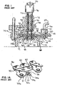
- the tool of Figure 1 generally includes a base 10 made from a length of steel channel and having a generally horizontal web portion 12 which supports a plurality of anvil plates 14.
- the width of the belt 28 determines the minimum length of the base 10.
- Belts typically have widths of, for example, 24, 42, or 60 inches.
- Apertures 16 and 18 are formed in the anvil plate 14 at locations which correspond to countersunk holes or perforations 20 and 21 in the belt fasteners 22, and also are formed in the underlying horizontal portion 12 of the base respectively.
- Each of the apertures 16 in the anvil plates is substantially centered in a button or rivet head forming bushing 24 which comprises a generally circular, upwardly extending rim. As described in greater detail below, each of the apertures and bushings 24 cooperates with one of the rivet assemblies 26 as the rivet assemblies are driven downward to form the lower rivet heads.
- Each of the hinge-type fasteners 22 includes an upper plate 32 and a lower plate 34 which are joined by a generally U-shaped center hinge loop portion 36 adapted to interfit with an opposite U-shaped portion of belt fasteners on an adjacent belt end (not shown) to form a hinge structure to receive a hinge pin (not shown).
- the countersunk holes or apertures 20, 21 for receiving rivets are formed in a predetermined pattern through each fastener plate 32, 34, the upper fastener plates 32 being countersunk on their top surfaces and the lower fastener plates being countersunk on their bottom surfaces.
- the preferred fastener plates each have five recessed apertures arranged in a W-shaped pattern.
- the fastener-receiving apertures or perforations are located about one-half inch from an adjacent perforation.
- the preferred fastener plates have an inboard, contoured edge 34a ( Figure 1A ) preferably in the form of a scalloped edge for the reasons described in U.S. Patent No. 6,053,308 .
- the upper plates 32 Prior to installation, the upper plates 32 are upwardly inclined relative to the lower plates 34 via the U-shaped portions 36 to facilitate insertion of the belt end 44 between the upper and lower plates. Installation of the rivets 46 ( FIG. 1 ) pushes the upper plates 32 downward, flexing the U-shaped portions 36 so that the belt end 44 is squeezed between the upper and lower plates.
- the fasteners 22 are maintained in a predetermined position by engagement of the countersunk portions of the apertures 21 of the lower fastener plates 34 with the upwardly projecting bushings 24 on the anvil plates 14, which assist in forming the lower rivet head.
- the strip of fasteners are locked into place at their inboard side by a gauge pin 50 which extends through the U-shaped portions 36 of the belt fasteners 22.
- a clamp 56 which herein comprises a generally horizontal clamping member 57 with screw handles 59 at each end for applying downward pressure to the clamping member.
- the illustrated clamping member 57 is a bar in the form of a length of square tubing, e.g., having a thin wall of about 0.125 inch thick. Particularly, for large belts of the five foot width, this tube clamping member becomes deflected or bent at the middle portion of the belt in either or both of the vertical and horizontal directions thereby reducing its effective clamping force.
- Each screw handle 59 comprises a generally L-shaped rod having a threaded portion 118 at its lower end and a nut 120 fixed to it above the threaded portion and inside the hollow tube.
- the threaded portions 118 of the screw handles are received in threaded bores 122 in the anvil plates 14 at the corners of the base. Clockwise rotation of the screw handles 59 through the nuts 120 and further into the threaded bores forces the clamping member downward to clamp the belt in place against the web portion 12 of the channel base 10.
- the threaded bores become filled or partially filled with coal dust or other debris and necessitate a cleaning to remove the coal dust accumulated therein.
- the belt end 44 is inserted between the upper and lower fastener plates 32 and 34, and rivet assemblies 26 are driven downwardly through the perforations 20 in the upper fastener plate, through the thickness of the belt end 44, and through the perforations 21 in the lower fastener plate.
- each of the illustrated rivet assemblies 26 includes a rivet 46 having a head at its upper end and a hollow lower end for receiving the upper end of an interfitting detachable pilot nail 60.
- the pilot nail has a sharpened point at its lower end for piercing the belt material and guiding the rivet assembly through the perforations 20, 21 in the fasteners and apertures in the anvil plates 14.
- the pilot nail has an integral upwardly extending pin portion at its upper end which fits within the hollow lower end of the rivet 46, and an integral annular shoulder 66 formed just below the pin.
- the shoulder 66 seats in the bushings 24, arresting the downward progress of the nail 60.
- the upper surface of the button 24 flares the hollow lower end of the rivet 46 outwardly as described in U.S. Pat. No. 4,258,461 .
- the rivet assemblies 26 are aligned and guided as they are driven by a plurality of substantially vertical bores 70 in a guide block assembly 78.
- An impact distributing driver which is either manual or power driven, is employed to transmit impact force such as from a single hammer 75 simultaneously to a plurality of rivet assemblies disposed within the bores 70 of the guide means 78.
- the guide block 72 preferably made of an elastomer, is part of the guide means or block assembly 78 supported in a rigid frame 91 and preferably includes alignment surfaces 79 for maintaining the guide block in one of a plurality of predetermined positions with respect to the base 10.
- the preferred driver 74 includes an impact upper end or cap 76 for receiving hammer blows and a plurality of downwardly extending drive pins or rods 77 which are fixed at their upper ends to the cap and adapted to be received within the bores 70 of the guide block 72.
- the drive rods are preferably arranged in a group corresponding to a group of perforations 20, 21 in a single fastener plate 32, 34 so that all of the rivet assemblies 26 for a particular fastener 22 may be driven simultaneously.
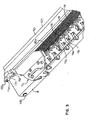
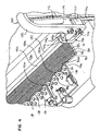
- the belt end is inserted into the gap between the upper and lower plates 32 and 34 and is positioned on a raised belt surface 80 ( Figure 5 ) which raises the belt up to at least the level of the top side of the lower fastener plate 34, preferably to a height above the upper front edge 34a ( Figure 1 ) of the lower plate 34 so that when the belt is pushed into the gap, the lower corner 28a of the belt end will not abut against this edge 34a on the lower plate and interfere or even stop the sliding insertion, as may occur in the prior art system illustrated in Figure 1 .
- this raised belt guiding surface 80 ( Figure 5 ) is formed on a plate 82 which is a horizontally oriented plate fastened to the top side of the web portion 12a of the channel base so as to provide an extra thickness from that shown in Figure 1 of the prior art.
- the raised surface 80 causes the belt end to slide more easily across the lower fastener plate 34 and rivet head forming bushings 24 and into abutment with a belt stop 83 ( Figure 2 ) thereby limiting any further insertion of the belt into the space between the upper and lower fastener plates.
- this belt raised surface 80 is also provided with an improved gripping or mechanical bite surface 82a in the form of an uneven surface having grooves, serrations 84 ( Figure 5 ) and/or raised points and ribs 85.
- grooves 84 between ribs provide some lowered areas into which the lower belt surface may be pushed and the ribs 85 provide some upward projections which are pressed into the lower surface of the belt.
- the gripping surface 82a is part of the raised surface 82 and comprises this series of parallel serrations or grooves and ribs running the length of the belt clamp surface and being parallel to the belt clamping member 157.
- the belt bottom surface is pressed with sufficient pressure to conform to the contour ribbed, gripping surface 82a.
- a number of different mechanical gripping surfaces 82a may be used, such as a roughened surface, non-parallel grooves, cross grooves, such as a knurled surface, or an attached, separate roughened substrate to provide an improved grip with the clamping bar to hold the belt end against shifting movement, particularly during the hammering of the succession of the belt fasteners and rivets into position along a long length of belt.
- the belt may be up to five feet in width.
- the belt clamping effectiveness is improved over the prior art such as illustrated in Figure 1 , by providing a stronger and more rigid construction for the clamping member 157 from that of the hollow, metal tube 57 ( Figure 1 ) having about a 1/8 inch thick metal wall thickness.
- the center portion of this hollow, thin wall metal tube may bend or be deflected by the belt particularly at the center thereof in either or both of the vertical and horizontal directions.
- the clamping member 157 is provided with a considerably thicker or larger cross-sectional portion preferably in the form of a contoured, solid bar 90.
- This illustrated solid bar has a contoured shape in the form of an inverted T with an upstanding central solid portion 90a ( Figure 2 ) and a lower horizontally extending flange portion 90b.
- the T-shape bar provides an increased, metal cross-sectional thickness over that of the hollow tubes shown in Figure 1 to resist bending and flex deflection in both the vertical and the horizontal directions.
- both upstanding portion 90a and lower, horizontal flange portion 90b have rectangular cross-sections which could be other shapes than rectangular.
- the bottom side of the larger width horizontal bar portion 90b engages the top of the belt and pushes the belt down with sufficient clamping pressure to have the mechanical grip with the underlying ribbed surface 82a at the underside of the belt.
- the clamping member 157 is guided for vertical movement between an upper position and a lower gripping position by a pair of upstanding end guides in the form of angled shaped bodies 94 ( Figures 2 and 4 ), which have a vertical slot 94a in a vertical flange 94b of the body.
- Vertical side walls 94c at the slot define a pair of spaced, vertical guide walls against which the vertical sides 90c of the lower horizontal, flange portion 90b of the clamping bar may abut and slide.
- the guide body 94 in this instance, is secured by fasteners to the channel base 10.
- the screw handles 59 had been replaced by improved locking handles or devices which provide a greater locking or clamping force for at the opposite ends of the clamping bar 90 than heretofore provided.
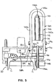
- an over-center toggle locking device having a U-shaped handle 102 which operates an over-center toggle clamp 100 to push the clamping bar 90 downwardly to cause a mechanical bite of the serrated surface 82a on the raised portion 82 which is located immediately beneath the clamping bar.
- the over-center toggle clamp is faster in terms of its clamping operation in that the handle 102 is swung only through a small arc to effect the belt clamping, as will be explained in greater detail below, rather than the slow rotations of the screw handles to screw down the prior art clamping device.
- the over-center toggle clamp 100 illustrated herein comprise a long, vertically extending, toggle rod 106 which has a lower hooked end 106a ( Figures 2 and 5 in the shape of a J) for hooking engagement under a horizontally extending anchor pin 108 which is secured to the channel base 10.
- the anchor pin is a round shaft extending through holes in the depending flanges 11 of the channel base.
- the toggle rod 106 extends vertically from its lower and hooked end to an upper end 106b ( Figures 2 and 5 ) located adjacent, a curved upper end 102a of the U-shaped handle 102.
- the upper end 106b of the toggle rod is formed with a screw thread and has one or more nuts 110 threaded thereon.
- the nuts 110 bear down against the top of a coiled compression spring 112 which encircles the upper portion end of the toggle rod 106.
- the compression spring is a heavy coiled spring which when compressed will provide a biasing, clamping force to the clamping bar 90 when the toggle handle is positioned in its over-center locking position.
- the spring 112 is located between the upper nut 110 and a central located roller shaft 114 which is journaled at its opposite ends by pins 114a to the opposite legs 102b of the U-shaped, over-center toggle handle 102.
- the pivoted handle In its unlocked position, the pivoted handle may extend to the left and counterclockwise direction as viewed in Figure 2 .
- the lower end of the U-shaped handle 102 is pivotally mounted on the ends of the clamping bar 90 for pivoting about a pivot axis through the center of a horizontal pivot pin 116 which spans a pair of spaced blocks or lugs 119, 121 which are fixedly connected to or integral with the opposite ends of the clamping bar 90.
- the lugs are located on opposite sides of the lower portion of the toggle rod 106 which extends vertically within the slot formed between the lugs. This allows the toggle rod 106 to pivot and to move back and forth across at the axis of rotation of the pivot pin 116 about which the entire U-shaped handle pivots.
- handle 102 and the upper end 106b of the toggle rod 106 will be pivoted outwardly away from the belt and the lower hooked end 106a of the toggle rod will be slightly lowered from engagement with the anchor pin 108.
- the handle is pivoted upwardly to turn about the central axis through its pivot pin 116, the lower hooked end 106a will rise slightly and be tightly hooked onto the horizontally extending anchor pin 108 on the channel base 10 and with further upward pivoting of the handle, the nut 110 at the top of toggle rod 106 will compress the compression spring 112 between the nut 110 and roller 114 until the handle 102 reaches the vertical, center position where the handle is straight vertically.
- the toggle rod 106 is also positioned in a vertical plane with the spring being compressed the maximum.
- the spring then slightly expands causing the over-center action where there will be a slight lengthening of the compressed spring.
- the spring force from the compressed, over-center spring is providing a downward force to the handle to pivot it further downward toward the belt.
- the compressed spring pushes down on the roller 114, roller shaft 114a, handle legs 102b, pivot pin 116, and lugs 119 and 121 and attached bar 90 and thereby pushes down the clamping bar 90 to clamp the belt end. Stop surfaces may be formed at various locations to stop the rotation of the handle in this over-center locking position, as shown in Figure 2 .
- the handle is pivoted outwardly from the belt and across the vertical center position to where the lower J-shaped end of the toggle rod is spaced slightly from the anchor pin 108.
- the clamping bar 90 and its attached over-center toggle clamps 100 may be detached from the channel base 10 by swinging the handles 102 downwardly until hooked ends 106a of the toggle rod 106 may be pulled and swung clear of their respective anchor pins 108 on the channel base. Then the clamping bar and its loosening toggle clamps may be lifted and separated from the channel base for separate transfer from the location of the finished belt splice.
- hinge belt fasteners may have various shapes and configurations, particularly along the inboard edges thereof, a contoured surface in the shape of scalloped configuration ( Figure 1A ) may be used.
- U.S. Patent No. 6,053,308 discloses a number of advantages for the hinge fastener shown in Figure 1A , having the contoured edge on the lower plate. For instance, removal of some of the web of metal at the outboard edge between the adjacent countersunk apertures for receiving the rivets allows the belt fastener to provide a lower profile for the fastener and this profiled contoured end sinks deeper into the belt carcass under the force from the rivets so that scrapping devices do not catch the scalloped edges of the fasteners.
- scalloped, outboard edge 34a of the lower plate 34 in Figure 1A it comprises a pair of rounded, projecting portions 34b that are merged by curving into a central, reversely curved depression portion 34c located between the curved projecting portions 34b.
- the projecting portions have the rivet receiving apertures therein.
- scalloped locating surfaces may be provided on the anvil base 10 to mate with the fastener scalloped edges when the lower plates are nested on the bushings 24 on the anvil plates 14a.
- a vertical end wall 82d on the raised plate 82 on the anvil base 10 is provided with a mating scallop surface for each of the scalloped, inboard edges of the strip of belt fasteners being riveted to the belt.
- the scalloped fasteners may have their scalloped edges mated to the scalloped wall 82d of the fixed plate 82 to minimize or prevent the lateral shifting of the inboard edges 34a relative to the hinged portions 36 being held by the gauge pin 50 at the opposite end of the fasteners.
- the scalloped surface on the plate end wall 82d comprises spaced, curved projections 130 to fit into the depression portions of the lower plates and spaced curved depressions 131 to receive the curved projecting portions the lower plates 34 of each of the string of belt fasteners.
- the scalloped edge on the tool provides an extra point of support and guidance for the fasteners to avoid a shifting of a lower plate 34 on the tool during the rivet fastening operation and a miss driving of a rivet.
- Figures 6-11 are directed to a variation of the embodiment shown in Figures 2-5 which is not part of the present invention.
- a separate riser plate 200 similar to plate 82 is provided.
- the riser plate 200 is not provided with the serrations or ridges 84, and instead has a smooth, top surface 202 thereof.
- the riser plate 200 is adapted to be used with the current, existing belt fastener installation tool commercially provided by applicant's assignee herein.
- the riser plate 200 is an add-on component that can aid in the installation process in a manner similar to that described for plate 82.
- the riser plate 200 is fastened to the underlining anvil plate 204 which is secured to and supported on the steel channel base 206.
- the end wall 208 of the riser plate 200 is disposed adjacent to the rivet forming bushings 210 of the anvil plate 204.
- the riser plate 200 is provided with a thickness such that the height of its end wall 208 is sufficient such that with the fasteners 22 secured in position on the anvil plate 204 as previously described with respect to the installation tool of Figures 2-5 , the insertion of the conveyor belt 28 between the fastener plates 32 and 34 can occur without having the end of the conveyor belt abut or catch against the lower plate 34 of the belt fasteners 22.
- the thickness of the riser plate 200 is generally greater than that of the lower plates 34 of the belt fasteners 22 such that the upper surface 202 of the riser plate 200 is raised to such an extent that the leading end of the conveyor belt 28 will not need to be lifted over the lower plates 34 of the belt fasteners 22 to be fit between the fastener plates 32 and 34.
- the end wall 208 has generally annular edge projections 212 extending therefrom generally toward the bushings 210 of the anvil plate 204.
- These scalloped projections 212 serve substantially the same purpose as the scalloped wall 82d of the plate 82.
- the projections 212 fit into the recesses 34c in the inboard edges 34a of the fastener lower plates 34. Accordingly, the fastener plates are now located securely not only at their outboard side at their loops 36 via the gauge pin 50 and the locating blocks 214 through which the gauge pin 50 extends, but also at their inboard side by the projections 212 configured to be snugly received in the lower plate recesses 34c.
- the top surface 202 is also smooth across its entire extent. In this manner, the riser plate 200 differs from the plate 82 in lacking any serrations or ridges 84, as previously mentioned. While not having the improved gripping action provided by these gripping features, the plate 200 also avoids having structure that could cause hang up during sliding of the belt along the belt surface 202 during belt insertion between the fastener plates 32 and 34.
- Figure 7 shows the riser plates 200 secured to the anvil plate in a conventional belt fastener installation tool including a J-screw clamp actuator 214 with a hollow, clamp bar 216 having a square shape in cross-section, as previously described.
- Figure 10 shows the separate riser plate 200 that is configured as an add-on for the existing tool, and particularly, to be fastened to the anvil plate 204 of Figure 11 that is used with the existing tool.
- Figure 8 shows one means of fastening the riser plate 200 to the existing anvil plate 204.
- Figure 9 shows an alternative means for securing the riser plate 200 to the existing anvil plate 204 via rivets 218 extending through the apertures 220 of the annular projections 212 of the riser plate 200.
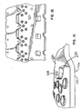
- Figures 12-16 are directed to the installation tool according to the present invention where the previously described anvil plates 14, 14a and 204 are formed integrally as a unitary component with the riser plates 82 and 200, respectively.
- FIGs 12 and 13 it can be seen that there is an anvil plate portion 222 that is offset from the raised riser plate portion 224 in the unitary anvil and riser plate member 226.
- This component is advantageous in that it avoids the need to machine the scalloped projections 228.
- the plate member 226 is preferably of a steel material that is formed on a punch press without the need for subsequent machining of the locating projections 228 thereof.
- these projections 228 extend from shoulder or transitional wall 230 of the plate member 226 outwardly from riser plate portion 224 toward and above the offset, recessed anvil plate portion 222 with the projections 228 extending down to the top surface of the anvil plate portion 222.
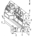
- the plate member 226 is adapted to for use on a belt fastener installation tool 232, as shown in Figs 14-16 .
- the base 234 is an extruded component such as of aluminum and has a raised portion 236 and a lowered or recessed portion 238.
- the raised portion 236 has a web 240 the upper surface 241 of which includes serrations or ridges 242 along the portion thereof under clamp bar 244. The remainder of the web surface 241 is free of such serrations 242.
- the lowered base portion 238 also has a web wall 246 with its upper surface 248 recessed below the surface portion 244 and serrated surface 242 so that a shoulder or step 250 is formed therebetween.
- the anvil and riser plate member 226 is secured to the base 234 so that the anvil plate portion 222 extends along the surface 248 and the riser plate portion 224 extends along the surface portion 244.
- the top pointed edges 242a of the serrations or ridges 242 are approximately level with the upper, smooth surface 251 of the riser plate portion 224. In this manner, the smooth surface 251 guides the belt as it is inserted between the fastener plates 32 and 34 over the lower plate 34.
- the inverted T-shaped clamp bar 245 is operated by a screw clamp 252 that includes an enlarged screw head handle 254 that rotates threaded shaft 256.
- the shaft extends through a threaded nut block 258 fixed to the bottom of the channel 240 so that turning the screw head 254 in the tightening direction lowers the clamp bar 244 onto the belt 28 to tightly compress it onto the serrations 242 therebelow.
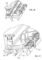
- the plate members 226 are each adapted to seat four fasteners 22 on the anvil plate portion 222 thereof. Depending on the length of the belt 28, several of such plate members 226 are secured to the recessed portion 238 of the extruded aluminum channel base 234, as shown in Figure 16 .
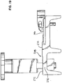
- Figures 17-19 are directed to another not claimed example of a belt fastener installation tool 260.
- the base 262 is also an extruded component, preferably of aluminum similar to base 234 in that it includes a raised portion 264 and a lowered portion 266.
- the entire raised belt guiding surface 268 is formed integrally on the web wall 270 of the base raised portion 264. Accordingly, a separate component that includes a raised surface portion such as the previously described riser plate portion 245a is avoided.
- the raised surface 268 includes a serrated surface portion 272 under the clamp bar 244 and a smooth surface portion 274 that extends toward the recessed surface 276 from the serrated surface portion 272, as can be seen in FIGS 18 and 19 .
- the smooth surface portion 274 allows the belt to ride thereover with a minimum of hang ups for smooth sliding of the belt 28 in between the belt fastener plates 32 and 34.
- the recessed surface 276 is formed on the top surface of the webwall 278 of the lowered base portion 266.
- the anvil plates 14b are separate components that are secured to the webwall 278 supported on surface 276 thereof.
- the base 262 has a shoulder surface 282 extending vertically between the raised surface 268 and the recessed surface 276.
- the shoulder surface 282 is scalloped to include edge projections 284 extending therefrom.
- the extrusion of the base 262 requires that these projections 284 be separately machined into the surface 282 and thus is less desirable from a manufacturing cost standpoint than the previously-described versions including scalloped projections formed or separate components, i.e. the rised plates 82 and 200, and the anvil and riser plate member 226.
- the anvil plates 14b have corresponding recesses 286 for being located by the projections 284 in a manner similar to the lower plates of the belt fasteners 22, as has been previously described.
Landscapes
- Engineering & Computer Science (AREA)
- General Engineering & Computer Science (AREA)
- Mechanical Engineering (AREA)
- Belt Conveyors (AREA)
- Clamps And Clips (AREA)
Claims (5)
- Installationswerkzeug (232) zum Aufbringen von Bandbefestigungseinrichtungen (22), die obere und untere Platten (32, 34) aufweisen, an Förderbändern (28), wobei das Installationswerkzeug (232) umfasst:eine Basis (234);ein einheitliches, einstückiges Amboss- und Stirnplattenelement (226) zum Befestigen an der Basis (234);einen ausgenommenen Ambossplattenabschnitt (222) des Plattenelements (226), der zum Tragen der Bandbefestigungseinrichtungen (22) daran konfiguriert ist, wobei die unteren Platten (34) damit in Eingriff stehen;einen erhöhten Stirnplattenabschnitt (224) des Plattenelements (226) benachbart zu und versetzt von der unteren ausgenommenen Ambossabschnittsplatte (222) zum Tragen eines vorausgehenden Endabschnitts des Bandes (28) zum Vorschub daran entlang und über die Platte (34) der Befestigungseinrichtung (22) an dem ausgenommenen Ambossplattenabschnitt (222); undAnordnungsvorsprünge (228) des Plattenelements (226) zwischen dem erhöhten Stirnplattenabschnitt (224) und dem ausgenommenen Ambossplattenabschnitt (222) zum Anordnen der unteren Platte (34) an dem Ambossplattenabschnitt (222),wobeidie Basis (234) einen erhöhten Abschnitt (236) und einen ausgenommenen Abschnitt (238) aufweist, undsich der ausgenommene Ambossplattenabschnitt (222) entlang einer oberen Fläche (248) des ausgenommenen Abschnitts (238) erstreckt,dadurch gekennzeichnet, dasssich der erhöhte Stirnplattenabschnitt (224) entlang eines oberen Flächenabschnitts (244) des erhöhten Abschnitts (236) erstreckt.
- Installationswerkzeug nach Anspruch 1, wobei das Plattenelement (226) obere Flächen des jeweiligen erhöhten Stirnplattenabschnitts (224) und des ausgenommenen Ambossabschnitts (222) davon sowie eine Schulterwand (230) aufweist, die sich dazwischen erstreckt, und sich die Anordnungsvorsprünge (228) aus der Schulterwand (230) zu und über den ausgenommenen Ambossplattenabschnitt (222) und abwärts zu der unteren Fläche davon erstrecken.
- Installationswerkzeug nach Anspruch 1, wobei die Basis (234) einen erhöhten Abschnitt (236) aufweist, der eine erhöhte Klemmfläche (241) davon aufweist, die eng benachbart dem erhöhten Stirnplattenabschnitt (224) des Plattenelements (226) ist, das an der Basis (234) befestigt ist, und das damit zusammenwirkt, um den vorausgehenden Endabschnitt des Bandes (28) daran zum Vorschub zwischen den Befestigungseinrichtungsplatten (32, 34) zu stützen und zu führen.
- Installationswerkzeug nach Anspruch 1, wobei die Basis (234) einen unteren horizontalen Stegabschnitt (246), der derart konfiguriert ist, das Plattenelement (226), das daran montiert ist, zu stützen, einen erhöhten horizontalen Stegabschnitt (240), der vertikal von dem unteren horizontalen Stegabschnitt (246) versetzt ist, um den vorausgehenden Endabschnitt des Bandes zum Klemmen daran zu tragen, Endschenkelabschnitte, die sich von den oberen und unteren horizontalen Stegabschnitten (240, 246) erstrecken, sowie einen Zwischenschenkelabschnitt aufweist, der zwischen den Endschenkelabschnitten beabstandet ist, wobei die Schenkelabschnitte zusammenwirken, um mit einer Trägerfläche in Eingriff zu treten, die die horizontalen Stegabschnitte (240, 246) darüber stützt.
- Installationswerkzeug nach Anspruch 4, wobei der erhöhte horizontale Stegabschnitt (240) einen Greifaufbau (242) entlang eines Abschnitts davon; und
eine Klemme (252) aufweist, um das Band (28) eng gegen den Greifaufbau (242) zu klemmen, wobei der vorausgehende Endabschnitt zwischen den Befestigungseinrichtungsplatten (32, 34) aufgenommen ist.
Applications Claiming Priority (2)
| Application Number | Priority Date | Filing Date | Title |
|---|---|---|---|
| US81029706P | 2006-06-02 | 2006-06-02 | |
| PCT/US2007/012986 WO2007143120A2 (en) | 2006-06-02 | 2007-06-01 | Belt fastening system |
Publications (3)
| Publication Number | Publication Date |
|---|---|
| EP2032305A2 EP2032305A2 (de) | 2009-03-11 |
| EP2032305A4 EP2032305A4 (de) | 2011-06-29 |
| EP2032305B1 true EP2032305B1 (de) | 2018-09-12 |
Family
ID=38802095
Family Applications (1)
| Application Number | Title | Priority Date | Filing Date |
|---|---|---|---|
| EP07795629.0A Active EP2032305B1 (de) | 2006-06-02 | 2007-06-01 | Gurtbefestigungssystem |
Country Status (6)
| Country | Link |
|---|---|
| US (1) | US8931155B2 (de) |
| EP (1) | EP2032305B1 (de) |
| AU (1) | AU2007254875B2 (de) |
| CA (1) | CA2654179C (de) |
| WO (1) | WO2007143120A2 (de) |
| ZA (1) | ZA200900003B (de) |
Families Citing this family (5)
| Publication number | Priority date | Publication date | Assignee | Title |
|---|---|---|---|---|
| US8151432B2 (en) | 2008-03-10 | 2012-04-10 | Flexible Steel Lacing Company | Conveyor belt splicing system and method |
| CA3037529A1 (en) | 2016-09-23 | 2018-03-29 | Flexible Steel Lacing Company | Applicator for conveyor belt fasteners |
| US11473649B2 (en) | 2016-09-23 | 2022-10-18 | Flexible Steel Lacing Company | Conveyor belt fastener applicators and fastener beds |
| US11412260B2 (en) * | 2018-10-29 | 2022-08-09 | Google Llc | Geometric transforms for image compression |
| PL445723A1 (pl) * | 2020-10-28 | 2024-10-21 | Flexible Steel Lacing Company | Łoża dla elementów złącznych dla aplikatorów elementów złącznych taśmy przenośnikowej |
Family Cites Families (24)
| Publication number | Priority date | Publication date | Assignee | Title |
|---|---|---|---|---|
| US1409742A (en) * | 1920-01-27 | 1922-03-14 | Walter A Ling | Belt-lacing device |
| US1385685A (en) * | 1920-12-04 | 1921-07-26 | Truck Tractor And Mfg Company | Belt-fastening device |
| US3141346A (en) | 1961-09-27 | 1964-07-21 | Union Supply Company | Means for joining flexible belts |
| US3176358A (en) | 1962-07-18 | 1965-04-06 | Leflon Henry Eugene | Fasteners for conveyor belts and the like |
| US3742557A (en) | 1971-05-14 | 1973-07-03 | Uniroyal Inc | Hinge fastener for conveyor belts |
| US4111080A (en) * | 1977-02-04 | 1978-09-05 | Flexible Steel Lacing Company | Staple fastening tool |
| US4144628A (en) * | 1977-06-09 | 1979-03-20 | Schick Jean Francois | Method and device for fixing joining clamps on a conveyor band, belt or the like |
| US4440336A (en) * | 1981-07-02 | 1984-04-03 | The Goodyear Tire & Rubber Company | Apparatus for attaching fasteners to belts |
| US4688711A (en) * | 1983-04-28 | 1987-08-25 | Flexible Steel Lacing Company | Driver for riveting fasteners to a belt |
| US5170924A (en) * | 1989-12-06 | 1992-12-15 | Flexible Steel Lacing Company | Fastening apparatus for securing belt fasteners to a conveyor belt |
| DE4140743C2 (de) * | 1991-12-11 | 1993-10-07 | Goro Sa | Vorrichtung zum Befestigen von Riemenverbindern aus in Reihe angeordneten Verbinderklammern auf den Gurtbandenden von Transportgurten |
| US5524808A (en) * | 1994-04-26 | 1996-06-11 | Flexible Steel Lacing Company | Powered multiple riveter |
| US6081995A (en) * | 1994-06-03 | 2000-07-04 | Mato Maschinen-Und Metallwarenfabrik Curt Matthaei Gmbh & Co. Kg | Belt Fastener installation Apparatus |
| US5906038A (en) * | 1994-06-03 | 1999-05-25 | Mato Maschinen-Und Metallwarenfabrik Curt Matthaei Gmbh & Co. Kg | Method of mounting belt fasteners on conveyor belts |
| DE4424041C1 (de) * | 1994-07-11 | 1995-12-07 | Goro Sa | Vorrichtung zum Befestigen von Riemenverbindern |
| DE19513483C2 (de) * | 1995-04-13 | 1998-11-19 | Mato Masch & Metallwaren | Vorrichtung zum Befestigen von Verbindungselementen an Gurtenden |
| US5680688A (en) * | 1996-02-15 | 1997-10-28 | Garner; James Melvin | Portable apparatus for affixing a lacer to a belt |
| US5664836A (en) * | 1996-03-29 | 1997-09-09 | Tachi-S Co., Ltd. | Reclining device for vehicle seat |
| US6053308A (en) | 1997-09-23 | 2000-04-25 | Flexible Steel Lacing Company | Rivet-hinged belt fastener with teeth |
| US6216851B1 (en) * | 1998-10-22 | 2001-04-17 | Flexible Steel Lacing Company | Rivet belt fastener |
| US6311393B1 (en) * | 1999-08-25 | 2001-11-06 | James M. Garner | Assembly for attaching fasteners to a belt |
| US7575114B2 (en) * | 2004-11-05 | 2009-08-18 | Cp Packaging, Inc. | Conveyor belt construction for a platen-type conveyor |
| US8028391B2 (en) * | 2006-05-26 | 2011-10-04 | Flexible Steel Lacing Company | Belt lacing apparatus |
| US8151432B2 (en) * | 2008-03-10 | 2012-04-10 | Flexible Steel Lacing Company | Conveyor belt splicing system and method |
-
2007
- 2007-06-01 US US12/520,388 patent/US8931155B2/en active Active
- 2007-06-01 EP EP07795629.0A patent/EP2032305B1/de active Active
- 2007-06-01 AU AU2007254875A patent/AU2007254875B2/en active Active
- 2007-06-01 WO PCT/US2007/012986 patent/WO2007143120A2/en not_active Ceased
- 2007-06-01 CA CA2654179A patent/CA2654179C/en active Active
-
2009
- 2009-01-01 ZA ZA200900003A patent/ZA200900003B/xx unknown
Non-Patent Citations (1)
| Title |
|---|
| None * |
Also Published As
| Publication number | Publication date |
|---|---|
| EP2032305A2 (de) | 2009-03-11 |
| AU2007254875A1 (en) | 2007-12-13 |
| ZA200900003B (en) | 2009-12-30 |
| CA2654179A1 (en) | 2007-12-13 |
| US8931155B2 (en) | 2015-01-13 |
| WO2007143120A2 (en) | 2007-12-13 |
| US20100319175A1 (en) | 2010-12-23 |
| EP2032305A4 (de) | 2011-06-29 |
| CA2654179C (en) | 2015-05-19 |
| WO2007143120A3 (en) | 2008-07-31 |
| AU2007254875B2 (en) | 2013-06-06 |
Similar Documents
| Publication | Publication Date | Title |
|---|---|---|
| CA2654179C (en) | Belt fastening system | |
| US8151432B2 (en) | Conveyor belt splicing system and method | |
| US5988318A (en) | Connection hook | |
| US20110314982A1 (en) | Sheet cutter and belt processing tool | |
| EP2736673B1 (de) | Vorrichtung und verfahren zur installation von bandbefestigungen auf förderbändern | |
| US4333217A (en) | Apparatus for stapling belt | |
| US5170924A (en) | Fastening apparatus for securing belt fasteners to a conveyor belt | |
| US4258461A (en) | Apparatus for applying belt fasteners to a belt | |
| CA2733320C (en) | Nailing plate | |
| US4111080A (en) | Staple fastening tool | |
| EP2084408B1 (de) | Gurtklemmvorrichtung und -verfahren | |
| US6272951B1 (en) | Joist hanger mounting tool | |
| AU1322899A (en) | Connecting element for elevator guide rail | |
| US4380109A (en) | Method for applying belt fasteners to a belt | |
| US20060010828A1 (en) | Siding installation tool | |
| US5044539A (en) | Apparatus for affixing fasteners to a conveyor belt | |
| EP0124990B1 (de) | Verfahren und Vorrichtung zum Vernieten von Befestigungselementen an einem Riemen | |
| EP4407094B1 (de) | Schienenklammerapplikatorwerkzeug und verfahren zu dessen betrieb | |
| US7568269B2 (en) | Power tool and method for connecting fasteners to belts | |
| WO1999019125A1 (en) | Steel rule cutting die with removable cutting units and method for using same | |
| US6962179B1 (en) | Floor jack | |
| US20230069414A1 (en) | Stable and Cleat Extraction Tool | |
| US20060278859A1 (en) | Lumber tool | |
| US3513530A (en) | Method for nailing together molding boards in the construction of molds | |
| EP0431918B1 (de) | Vorrichtung zur Befestigung von Verbindungselementen an einem Förderband |
Legal Events
| Date | Code | Title | Description |
|---|---|---|---|
| PUAI | Public reference made under article 153(3) epc to a published international application that has entered the european phase |
Free format text: ORIGINAL CODE: 0009012 |
|
| 17P | Request for examination filed |
Effective date: 20090102 |
|
| AK | Designated contracting states |
Kind code of ref document: A2 Designated state(s): AT BE BG CH CY CZ DE DK EE ES FI FR GB GR HU IE IS IT LI LT LU LV MC MT NL PL PT RO SE SI SK TR |
|
| AX | Request for extension of the european patent |
Extension state: AL BA HR MK RS |
|
| DAX | Request for extension of the european patent (deleted) | ||
| A4 | Supplementary search report drawn up and despatched |
Effective date: 20110601 |
|
| 17Q | First examination report despatched |
Effective date: 20120629 |
|
| STAA | Information on the status of an ep patent application or granted ep patent |
Free format text: STATUS: EXAMINATION IS IN PROGRESS |
|
| GRAP | Despatch of communication of intention to grant a patent |
Free format text: ORIGINAL CODE: EPIDOSNIGR1 |
|
| STAA | Information on the status of an ep patent application or granted ep patent |
Free format text: STATUS: GRANT OF PATENT IS INTENDED |
|
| INTG | Intention to grant announced |
Effective date: 20180327 |
|
| GRAS | Grant fee paid |
Free format text: ORIGINAL CODE: EPIDOSNIGR3 |
|
| GRAA | (expected) grant |
Free format text: ORIGINAL CODE: 0009210 |
|
| STAA | Information on the status of an ep patent application or granted ep patent |
Free format text: STATUS: THE PATENT HAS BEEN GRANTED |
|
| AK | Designated contracting states |
Kind code of ref document: B1 Designated state(s): AT BE BG CH CY CZ DE DK EE ES FI FR GB GR HU IE IS IT LI LT LU LV MC MT NL PL PT RO SE SI SK TR |
|
| REG | Reference to a national code |
Ref country code: GB Ref legal event code: FG4D |
|
| REG | Reference to a national code |
Ref country code: CH Ref legal event code: EP |
|
| REG | Reference to a national code |
Ref country code: IE Ref legal event code: FG4D |
|
| REG | Reference to a national code |
Ref country code: DE Ref legal event code: R096 Ref document number: 602007056130 Country of ref document: DE |
|
| REG | Reference to a national code |
Ref country code: AT Ref legal event code: REF Ref document number: 1039974 Country of ref document: AT Kind code of ref document: T Effective date: 20181015 |
|
| REG | Reference to a national code |
Ref country code: NL Ref legal event code: MP Effective date: 20180912 |
|
| REG | Reference to a national code |
Ref country code: LT Ref legal event code: MG4D |
|
| PG25 | Lapsed in a contracting state [announced via postgrant information from national office to epo] |
Ref country code: BG Free format text: LAPSE BECAUSE OF FAILURE TO SUBMIT A TRANSLATION OF THE DESCRIPTION OR TO PAY THE FEE WITHIN THE PRESCRIBED TIME-LIMIT Effective date: 20181212 Ref country code: LT Free format text: LAPSE BECAUSE OF FAILURE TO SUBMIT A TRANSLATION OF THE DESCRIPTION OR TO PAY THE FEE WITHIN THE PRESCRIBED TIME-LIMIT Effective date: 20180912 Ref country code: SE Free format text: LAPSE BECAUSE OF FAILURE TO SUBMIT A TRANSLATION OF THE DESCRIPTION OR TO PAY THE FEE WITHIN THE PRESCRIBED TIME-LIMIT Effective date: 20180912 Ref country code: GR Free format text: LAPSE BECAUSE OF FAILURE TO SUBMIT A TRANSLATION OF THE DESCRIPTION OR TO PAY THE FEE WITHIN THE PRESCRIBED TIME-LIMIT Effective date: 20181213 Ref country code: FI Free format text: LAPSE BECAUSE OF FAILURE TO SUBMIT A TRANSLATION OF THE DESCRIPTION OR TO PAY THE FEE WITHIN THE PRESCRIBED TIME-LIMIT Effective date: 20180912 |
|
| PG25 | Lapsed in a contracting state [announced via postgrant information from national office to epo] |
Ref country code: ES Free format text: LAPSE BECAUSE OF FAILURE TO SUBMIT A TRANSLATION OF THE DESCRIPTION OR TO PAY THE FEE WITHIN THE PRESCRIBED TIME-LIMIT Effective date: 20180912 Ref country code: LV Free format text: LAPSE BECAUSE OF FAILURE TO SUBMIT A TRANSLATION OF THE DESCRIPTION OR TO PAY THE FEE WITHIN THE PRESCRIBED TIME-LIMIT Effective date: 20180912 |
|
| REG | Reference to a national code |
Ref country code: AT Ref legal event code: MK05 Ref document number: 1039974 Country of ref document: AT Kind code of ref document: T Effective date: 20180912 |
|
| PG25 | Lapsed in a contracting state [announced via postgrant information from national office to epo] |
Ref country code: IT Free format text: LAPSE BECAUSE OF FAILURE TO SUBMIT A TRANSLATION OF THE DESCRIPTION OR TO PAY THE FEE WITHIN THE PRESCRIBED TIME-LIMIT Effective date: 20180912 Ref country code: EE Free format text: LAPSE BECAUSE OF FAILURE TO SUBMIT A TRANSLATION OF THE DESCRIPTION OR TO PAY THE FEE WITHIN THE PRESCRIBED TIME-LIMIT Effective date: 20180912 Ref country code: PL Free format text: LAPSE BECAUSE OF FAILURE TO SUBMIT A TRANSLATION OF THE DESCRIPTION OR TO PAY THE FEE WITHIN THE PRESCRIBED TIME-LIMIT Effective date: 20180912 Ref country code: NL Free format text: LAPSE BECAUSE OF FAILURE TO SUBMIT A TRANSLATION OF THE DESCRIPTION OR TO PAY THE FEE WITHIN THE PRESCRIBED TIME-LIMIT Effective date: 20180912 Ref country code: AT Free format text: LAPSE BECAUSE OF FAILURE TO SUBMIT A TRANSLATION OF THE DESCRIPTION OR TO PAY THE FEE WITHIN THE PRESCRIBED TIME-LIMIT Effective date: 20180912 Ref country code: RO Free format text: LAPSE BECAUSE OF FAILURE TO SUBMIT A TRANSLATION OF THE DESCRIPTION OR TO PAY THE FEE WITHIN THE PRESCRIBED TIME-LIMIT Effective date: 20180912 Ref country code: IS Free format text: LAPSE BECAUSE OF FAILURE TO SUBMIT A TRANSLATION OF THE DESCRIPTION OR TO PAY THE FEE WITHIN THE PRESCRIBED TIME-LIMIT Effective date: 20190112 |
|
| PG25 | Lapsed in a contracting state [announced via postgrant information from national office to epo] |
Ref country code: SK Free format text: LAPSE BECAUSE OF FAILURE TO SUBMIT A TRANSLATION OF THE DESCRIPTION OR TO PAY THE FEE WITHIN THE PRESCRIBED TIME-LIMIT Effective date: 20180912 Ref country code: PT Free format text: LAPSE BECAUSE OF FAILURE TO SUBMIT A TRANSLATION OF THE DESCRIPTION OR TO PAY THE FEE WITHIN THE PRESCRIBED TIME-LIMIT Effective date: 20190112 |
|
| REG | Reference to a national code |
Ref country code: DE Ref legal event code: R097 Ref document number: 602007056130 Country of ref document: DE |
|
| PLBE | No opposition filed within time limit |
Free format text: ORIGINAL CODE: 0009261 |
|
| STAA | Information on the status of an ep patent application or granted ep patent |
Free format text: STATUS: NO OPPOSITION FILED WITHIN TIME LIMIT |
|
| PG25 | Lapsed in a contracting state [announced via postgrant information from national office to epo] |
Ref country code: DK Free format text: LAPSE BECAUSE OF FAILURE TO SUBMIT A TRANSLATION OF THE DESCRIPTION OR TO PAY THE FEE WITHIN THE PRESCRIBED TIME-LIMIT Effective date: 20180912 |
|
| 26N | No opposition filed |
Effective date: 20190613 |
|
| PG25 | Lapsed in a contracting state [announced via postgrant information from national office to epo] |
Ref country code: SI Free format text: LAPSE BECAUSE OF FAILURE TO SUBMIT A TRANSLATION OF THE DESCRIPTION OR TO PAY THE FEE WITHIN THE PRESCRIBED TIME-LIMIT Effective date: 20180912 |
|
| PG25 | Lapsed in a contracting state [announced via postgrant information from national office to epo] |
Ref country code: MC Free format text: LAPSE BECAUSE OF FAILURE TO SUBMIT A TRANSLATION OF THE DESCRIPTION OR TO PAY THE FEE WITHIN THE PRESCRIBED TIME-LIMIT Effective date: 20180912 |
|
| REG | Reference to a national code |
Ref country code: CH Ref legal event code: PL |
|
| GBPC | Gb: european patent ceased through non-payment of renewal fee |
Effective date: 20190601 |
|
| REG | Reference to a national code |
Ref country code: BE Ref legal event code: MM Effective date: 20190630 |
|
| PG25 | Lapsed in a contracting state [announced via postgrant information from national office to epo] |
Ref country code: TR Free format text: LAPSE BECAUSE OF FAILURE TO SUBMIT A TRANSLATION OF THE DESCRIPTION OR TO PAY THE FEE WITHIN THE PRESCRIBED TIME-LIMIT Effective date: 20180912 |
|
| PG25 | Lapsed in a contracting state [announced via postgrant information from national office to epo] |
Ref country code: GB Free format text: LAPSE BECAUSE OF NON-PAYMENT OF DUE FEES Effective date: 20190601 Ref country code: IE Free format text: LAPSE BECAUSE OF NON-PAYMENT OF DUE FEES Effective date: 20190601 |
|
| PG25 | Lapsed in a contracting state [announced via postgrant information from national office to epo] |
Ref country code: LI Free format text: LAPSE BECAUSE OF NON-PAYMENT OF DUE FEES Effective date: 20190630 Ref country code: CH Free format text: LAPSE BECAUSE OF NON-PAYMENT OF DUE FEES Effective date: 20190630 Ref country code: BE Free format text: LAPSE BECAUSE OF NON-PAYMENT OF DUE FEES Effective date: 20190630 Ref country code: LU Free format text: LAPSE BECAUSE OF NON-PAYMENT OF DUE FEES Effective date: 20190601 |
|
| PG25 | Lapsed in a contracting state [announced via postgrant information from national office to epo] |
Ref country code: CY Free format text: LAPSE BECAUSE OF FAILURE TO SUBMIT A TRANSLATION OF THE DESCRIPTION OR TO PAY THE FEE WITHIN THE PRESCRIBED TIME-LIMIT Effective date: 20180912 |
|
| PG25 | Lapsed in a contracting state [announced via postgrant information from national office to epo] |
Ref country code: HU Free format text: LAPSE BECAUSE OF FAILURE TO SUBMIT A TRANSLATION OF THE DESCRIPTION OR TO PAY THE FEE WITHIN THE PRESCRIBED TIME-LIMIT; INVALID AB INITIO Effective date: 20070601 Ref country code: MT Free format text: LAPSE BECAUSE OF FAILURE TO SUBMIT A TRANSLATION OF THE DESCRIPTION OR TO PAY THE FEE WITHIN THE PRESCRIBED TIME-LIMIT Effective date: 20180912 |
|
| PGFP | Annual fee paid to national office [announced via postgrant information from national office to epo] |
Ref country code: DE Payment date: 20250627 Year of fee payment: 19 |
|
| PGFP | Annual fee paid to national office [announced via postgrant information from national office to epo] |
Ref country code: FR Payment date: 20250625 Year of fee payment: 19 |
|
| PGFP | Annual fee paid to national office [announced via postgrant information from national office to epo] |
Ref country code: CZ Payment date: 20250523 Year of fee payment: 19 |