EP2033014B1 - Émetteur modulé en polarisation pour radar météorologique - Google Patents
Émetteur modulé en polarisation pour radar météorologique Download PDFInfo
- Publication number
- EP2033014B1 EP2033014B1 EP07764779A EP07764779A EP2033014B1 EP 2033014 B1 EP2033014 B1 EP 2033014B1 EP 07764779 A EP07764779 A EP 07764779A EP 07764779 A EP07764779 A EP 07764779A EP 2033014 B1 EP2033014 B1 EP 2033014B1
- Authority
- EP
- European Patent Office
- Prior art keywords
- signal
- coupler
- signal paths
- phase
- transmitter according
- Prior art date
- Legal status (The legal status is an assumption and is not a legal conclusion. Google has not performed a legal analysis and makes no representation as to the accuracy of the status listed.)
- Active
Links
Images



Classifications
-
- H—ELECTRICITY
- H01—ELECTRIC ELEMENTS
- H01Q—ANTENNAS, i.e. RADIO AERIALS
- H01Q21/00—Antenna arrays or systems
- H01Q21/24—Combinations of antenna units polarised in different directions for transmitting or receiving circularly and elliptically polarised waves or waves linearly polarised in any direction
- H01Q21/245—Combinations of antenna units polarised in different directions for transmitting or receiving circularly and elliptically polarised waves or waves linearly polarised in any direction provided with means for varying the polarisation
-
- G—PHYSICS
- G01—MEASURING; TESTING
- G01S—RADIO DIRECTION-FINDING; RADIO NAVIGATION; DETERMINING DISTANCE OR VELOCITY BY USE OF RADIO WAVES; LOCATING OR PRESENCE-DETECTING BY USE OF THE REFLECTION OR RERADIATION OF RADIO WAVES; ANALOGOUS ARRANGEMENTS USING OTHER WAVES
- G01S13/00—Systems using the reflection or reradiation of radio waves, e.g. radar systems; Analogous systems using reflection or reradiation of waves whose nature or wavelength is irrelevant or unspecified
- G01S13/88—Radar or analogous systems specially adapted for specific applications
- G01S13/95—Radar or analogous systems specially adapted for specific applications for meteorological use
- G01S13/951—Radar or analogous systems specially adapted for specific applications for meteorological use ground based
-
- G—PHYSICS
- G01—MEASURING; TESTING
- G01S—RADIO DIRECTION-FINDING; RADIO NAVIGATION; DETERMINING DISTANCE OR VELOCITY BY USE OF RADIO WAVES; LOCATING OR PRESENCE-DETECTING BY USE OF THE REFLECTION OR RERADIATION OF RADIO WAVES; ANALOGOUS ARRANGEMENTS USING OTHER WAVES
- G01S7/00—Details of systems according to groups G01S13/00, G01S15/00, G01S17/00
- G01S7/02—Details of systems according to groups G01S13/00, G01S15/00, G01S17/00 of systems according to group G01S13/00
- G01S7/024—Details of systems according to groups G01S13/00, G01S15/00, G01S17/00 of systems according to group G01S13/00 using polarisation effects
-
- G—PHYSICS
- G01—MEASURING; TESTING
- G01S—RADIO DIRECTION-FINDING; RADIO NAVIGATION; DETERMINING DISTANCE OR VELOCITY BY USE OF RADIO WAVES; LOCATING OR PRESENCE-DETECTING BY USE OF THE REFLECTION OR RERADIATION OF RADIO WAVES; ANALOGOUS ARRANGEMENTS USING OTHER WAVES
- G01S7/00—Details of systems according to groups G01S13/00, G01S15/00, G01S17/00
- G01S7/02—Details of systems according to groups G01S13/00, G01S15/00, G01S17/00 of systems according to group G01S13/00
- G01S7/03—Details of HF subsystems specially adapted therefor, e.g. common to transmitter and receiver
-
- Y—GENERAL TAGGING OF NEW TECHNOLOGICAL DEVELOPMENTS; GENERAL TAGGING OF CROSS-SECTIONAL TECHNOLOGIES SPANNING OVER SEVERAL SECTIONS OF THE IPC; TECHNICAL SUBJECTS COVERED BY FORMER USPC CROSS-REFERENCE ART COLLECTIONS [XRACs] AND DIGESTS
- Y02—TECHNOLOGIES OR APPLICATIONS FOR MITIGATION OR ADAPTATION AGAINST CLIMATE CHANGE
- Y02A—TECHNOLOGIES FOR ADAPTATION TO CLIMATE CHANGE
- Y02A90/00—Technologies having an indirect contribution to adaptation to climate change
- Y02A90/10—Information and communication technologies [ICT] supporting adaptation to climate change, e.g. for weather forecasting or climate simulation
Definitions
- the invention relates to a polarization-modulated transmitter of a weather radar, according to the preamble of claim 1.
- weather radar When capturing weather data, weather radar is used to observe the weather, for example, near airports.
- the weather radars emit electromagnetic waves and receive the electromagnetic waves scattered, among other things, on precipitation particles in order to evaluate them. For example, electromagnetic waves are scattered at larger raindrops due to their oval shape so that the horizontal field component is reflected more strongly than the vertical field component.
- Many weather radars emit an electromagnetic wave having a single field component, ie, the electromagnetic wave is "simply" linearly polarized. Around In this regard, for the evaluation to emit a suitable electromagnetic wave, this is usually polarized horizontally.
- polarimetric weather radars which emit electromagnetic waves in two orthogonal polarized field components.
- the backscattered, received pulse is decomposed into the two field components and fed to a respective receiver.
- each radiated pulse contains both field components that are polarized orthogonal to each other.
- the pulse radiated by the antenna is provided by a transmitter whose power is split into two channels, one for each field component.
- the simultaneous polarization By dividing the transmission power of the transmitter to two channels in the simultaneous polarization halves the available transmission power for each of the two channels.
- the linear depolarization of the received signal can not be measured since this requires that a linearly polarized signal be emitted and the orthogonal polarized field components are measured. This is not directly possible with the simultaneous polarization.
- a single transmitter is switched between the two channels for the two orthogonal polarized field components.
- the transmitter gives all the power to a channel which is fed to a polarization port of the antenna, being alternately switched between the two channels from pulse to pulse or after a predetermined number of pulses.
- a ferrite switch or a mechanical switch serves as a high-power switch. Ferrite switches are very expensive and prone. Due to the high switching speed, the mechanical switches have to be synchronized with the pulse repetition frequency of the weather radar and usually only work if several pulses are emitted between successive switches.
- the disadvantage here is that the mechanical high-performance switch does not work in real time and is therefore very slow. A correlation between the rotational speed of the antenna of the weather radar and the transmitter is difficult.
- Fig. 6 11 is a polarization-modulated transmitter, in particular for a weather radar, in which for each polarization component an electromagnetic pulse generator is provided, which is radiated and received via a common antenna. Since the two transmit signals are generated by different transmit amplifiers, they are so strongly decorrelated with respect to their waveform that a precise measurement is no longer possible. Furthermore, the respectively unneeded transmitters must be turned off to emit alternating polarizations.
- the object of the invention is therefore to provide a transmitter according to the preamble of claim 1, which is simpler in construction, the fast switching between the modes allows simultaneous and switched polarization, has a good correlation of the polarized pulses, the available transmit power exploits as efficiently as possible and can be realized inexpensively.
- the high-frequency signal can preferably be fed to the signal paths by means of a pulse modulator. This allows a simple way of pulse generation.
- the phase modulator may preferably be a phase shifter designed as a fast-switching electronic or microelectromechanically switched (“MEMS”) phase shifter.
- MEMS microelectromechanically switched
- the coupler is preferably a magic T or hybrid (quadrature hybrid) in waveguides, a branch-line coupler or a ring coupler (hybrid ring) "," rat-race coupler ”) are designed for strip conductors and as branching couplers for coaxial cables.
- these can be configured as a klystron, cross field amplifier, traveling-wave tube, grid-controlled tube or transistor amplifier.
- a pulse modulation is easily possible by the power supply can be modulated.
- a pulse modulation via an electrode designed as a grid is possible with which the electron beam can be switched on or off.
- simple directional lines i. Isolators, designed to protect the transmission amplifiers, if the isolation by the coupler should not be sufficient.
- the signal of the signal paths can be coupled out to receivers which are connected to a processor which controls at least one predistorter arranged in a signal path in front of the transmission amplifier with regard to the predistortion of the signal.
- a good quality of the transmission signals is achieved, so that the signals fed into the coupler have a high correlation.
- Each transmit signal can be coupled out as a test signal, mixed and fed to the processor, which calculates the optimal predistortion and controls a corresponding predistorter in one of the signal paths.
- the signal of both signal paths can be predistorted, or one signal of one signal path serves as a reference, and only the signal of the other signal path is distorted. It is also possible that the signals of the two signal paths are coupled in addition or only behind the coupler in order to compensate for possible asymmetries of the coupler by the predistortion.
- a correlation can also take place via an I / Q demodulator, which supplies phase and amplitude information via a complex phasor as an output signal.
- the I / Q demodulator is preferably calibrated.
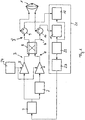
- Fig. 1 shows a weather radar with a first embodiment of a polarization modulated transmitter.
- the transmitter has at least two signal paths 3, 4, to which the same high-frequency signal is preferably supplied from a pulse modulator 2.
- Each of the signal paths 3, 4 has at least one transmission amplifier 5, 6.
- the signal paths 3, 4 are coupled via a coupler 8, so that the pulses arriving at the coupler 8 are entangled.
- the at least two signal paths 3, 4 are provided for a different polarization of the signals.
- a phase modulator 7 is arranged in the signal path 4.
- the entangled by the coupler 8 pulses are circulators 9, 10 can be fed.
- the two signal paths 3 ', 4' behind the coupler 8 serve the polarization of the radiated wave through the antenna 1.
- the exciter of the antenna 1 thus has as it were two gates, so that the polarization with the emission of the signal comes about, and the polarization indicates the position of the electric field component relative to the ground.
- the circulators 9, 10 serve to separate a transmitted or radiated signal from a received signal.
- the antenna 1 also receives electromagnetic pulses and passes them via the circulators 9, 10 to a receiver 21, which has two receiving channels 11, 12 for the received electromagnetic pulses.
- the received electromagnetic pulses are evaluated as a function of the radiated signal or pulse.
- One of the receiving channels 11, 12 evaluates the vertically polarized component and the other receiving channel 11, 12 the horizontally polarized component.
- the recipient also has at least one oscillator 22, which is connected to the receiving channels 11, 12, and a device for transmitting signal generation 23.
- the two signal paths 3, 4 in Fig. 1 High-frequency signal supplied via the pulse modulator 2 can also be displayed in addition to the direct modulation shown in FIG Device for transmitting signal generation 23 are modulated in mixers, so that the ready-mixed signal is already modulated. Furthermore, the high-frequency pulse modulation can be performed by generating a high-to-intermediate frequency signal with a digital-to-analog converter, wherein the intermediate frequency signal is pulse-modulated. A combination of the aforementioned types of high-frequency pulse modulation is also possible.
- the signal received via the antenna 1 is supplied to the signal processor 25 for evaluation via the two receiving channels 11, 12, wherein in the signal processor 25 for each receiving channel 11, 12 a Transmission signal compression means 28, 29 is provided.
- the transmission signal compression means 28, 29 is further connected to the device for transmitting signal generation 23 and receives from each of these the transmission signal.
- the described modulation of the transmission signal enables the signal processor 25 to uniquely assign the signal received at a particular time to a room cell.
- all portions of the transmission signal that passes through the space cell coherently integrated, whereby the sensitivity of the radar is significantly increased.
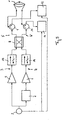
- a variant of the pulse compression radar Fig. 2 is that in Fig. 3 schematically illustrated frequency modulated continuous wave radar (FMCW, frequency modulated continuous wave).
- FMCW frequency modulated continuous wave radar
- the FMCW radar eliminates the transmit pulse and / or the RF pulse modulator.
- the transmitter permanently emits a repetitive frequency ramp. As the transmitter operates permanently, no circulators are used to decouple the transmit and receive signals. Instead, an FMCW radar operates with two antennas 1, one being used for transmission and the other for reception.
- the coupler 8 is off Fig. 1 with the gates TOR1, TOR2, TOR3, TOR4 shown in more detail.
- the gate TOR1 is the input port of the coupler 8 connected to the transmission amplifier 5 in the signal path 3.
- the port TOR4 is the input port of the coupler 8 connected to the transmission amplifier 6 in the signal path 4.
- the port TOR2 is the output port of the coupler 8 connected to the circulator 9
- the gate TOR3 is the output port of the coupler 8 connected to the circulator 10 Fig.
- 1 represented embodiment can be adjusted by adjusting the phase position of the signal at the gate TOR3 relative to the phase of the signal at the gate TOR1 at the same amplitude of the input to the gates TOR1 and TOR4 signal, the amplitude of the output signals at the gates TOR2 and TOR3.
- the amplitudes at the gate TOR2 constructive and destructive overlap at the gate TOR3, so that the entire power of both input signals is delivered to the gate TOR2.
- the entire power is then supplied in the signal path 3 to the circulator 9, which for example horizontally polarizes the signal, so that a horizontally polarized wave of the antenna 1 can be supplied.
- the construction of the coupler depends on the selected type of service.
- waveguides for example, a magic T or a hybrid (quadrature hybrid) can be used.
- a branch-line coupler or a ring-coupler for example, a branching coupler can be used.
- 90 ° hybrid is derived from the behavior of the coupler when only one signal is fed to the port TOR1.
- the signal at gate TOR1 is then divided into gates TOR2 and TOR3, the phase shift of the two outgoing waves at gates TOR2 and TOR4 being 90 °.
- Three modes of operation can be distinguished on the gates TOR 1 and TOR 4 due to different amplitude and phase of the signals.
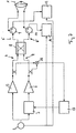
- the correlation of the two signals in the signal paths 3, 4 is achieved by mixing the decoupled signals in a mixer 18 and supplying them to the processor 17 in order to control the predistorter.
- one of the two signals from the signal paths can still be delayed via a calibrated phase shifter in order to maximize the output signal of the mixer 18.
- the signals of the signal paths are coupled behind the coupler 8 to compensate for any imbalances of the coupler 8 by the control of the predistortion.
- the device for transmitting signal generation 23 and the oscillator or oscillators 23 are not shown. This in Fig. 7 illustrated However, the embodiment can to that extent the in Fig. 1 correspond to the embodiment shown.
- the use of the transmitter according to the invention in an in Fig. 2 or 3 shown polarization-modulated pulse compression radar or FMCW radar is also possible.
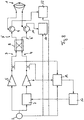
- Fig. 8 an embodiment is shown in which the correlation of the two signals in the signal paths 3, 4 is achieved via an I / Q demodulator 19 to which the decoupled signals of the signal paths 3, 4 are supplied.
- the I / Q demodulator 19 provides the phase and amplitude information via a complex phasor as an output to the processor 17 which controls the predistorter.
- the I / Q demodulator 19 receives a reference signal for the evaluation of the phase and amplitude information from the generator 2.
- the I / Q demodulator is calibrated.
- the device for transmitting signal generation 23 and the oscillator or oscillators 23 are not shown. This in Fig. 8
- the embodiment shown can to that extent in the Fig. 1 correspond to the embodiment shown.
- the use of the transmitter according to the invention in an in Fig. 2 or 3 shown polarization-modulated pulse compression radar or FMCW radar is also possible.
Landscapes
- Engineering & Computer Science (AREA)
- Radar, Positioning & Navigation (AREA)
- Remote Sensing (AREA)
- Physics & Mathematics (AREA)
- Computer Networks & Wireless Communication (AREA)
- General Physics & Mathematics (AREA)
- Electromagnetism (AREA)
- Radar Systems Or Details Thereof (AREA)
Claims (11)
- Emetteur modulé en polarisation pour un radar météorologique, avec une antenne (1), au moins deux circuits (3 ; 4), auxquels le même signal haute fréquence est transmis, un modulateur de phase (7) pour une modulation de phase dans un desdits au moins deux circuits (3 ; 4), et un coupleur (8) auquel sont connectés lesdits circuits (3 ; 4), et dont les sorties sont reliées à ladite antenne (1), où ledit modulateur de phase est prévu pour une modulation de polarisation du signal émis sur ladite antenne (1), caractérisé en ce que dans chaque dit circuit (3 ; 4) est agencé un amplificateur d'émission (5 ; 6), et que le signal haute fréquence est d'abord modulé en phase par ledit modulateur de phase (7) dans un desdits circuits (3 ; 4), et est ensuite amplifié dans lesdits amplificateurs (5 ; 6), puis est délivré audit coupleur (8).
- Emetteur selon la revendication 1, caractérisé en ce que ledit signal haute fréquence est alimenté au travers d'un modulateur d'impulsions (2).
- Emetteur selon la revendication 1 ou 2, caractérisé en ce que ledit modulateur de phase (7) est un déphaseur.
- Emetteur selon l'une des revendications 1 à 3, caractérisé en ce que ledit coupleur (8) est un hybride ou une jonction hybride.
- Emetteur selon l'une des revendications 1 à 3, caractérisé en ce que ledit coupleur (8) est un coupleur de branchement ou un coupleur en anneau.
- Emetteur selon l'une des revendications 1 à 5, caractérisé en ce que lesdits amplificateurs d'émission (5 ; 6) font fonction de klystron, ou amplificateur à champ croisé, ou tube à ondes progressives, ou tube commandé par grille, ou amplificateur à transistor.
- Emetteur selon l'une des revendications 1 à 6, caractérisé en ce qu'un isolateur (13 ; 14) est systématiquement disposé entre lesdits amplificateurs d'émission (5 ; 6) et ledit coupleur (8) , dans lesdits circuits (3 ; 4)
- Emetteur selon l'une des revendications 1 à 7, caractérisé en ce que le signal desdits circuits (3 ; 4) est déclenché à l'arrivée sur des récepteurs (15 ; 16) qui sont liés à un processeur (17), avec lequel au moins un préaccentuateur disposé dans un dit circuit (3 ; 4) devant ledit amplificateur d'émission (5 ; 6) est piloté par rapport à la prédistorsion et par rapport audit modulateur de phase (7) relatif à la modulation de phase de l'un des signaux desdits circuits (3 ; 4).
- Emetteur selon la revendication 8, caractérisé en ce que lesdits récepteurs (15 ; 16) sont chacun couplé avec ledit modulateur d'impulsions (2) pour la réception d'un signal de référence.
- Emetteur selon la revendication 8 ou 9, caractérisé en ce qu'un mélangeur (18) est prévu couplé entre lesdits deux circuits (3 ; 4) et ledit processeur (13) pour le pilotage dudit préaccentuateur et dudit modulateur de phase (7) en dépendance du signal mixé.
- Emetteur selon la revendication 8 ou 9, caractérisé en ce qu'un démodulateur I/Q (19) est prévu pour l'obtention de l'information de phase et d'amplitude des signaux desdits circuits (3 ; 4) est prévu couplé entre lesdits deux circuits (3 ; 4) et ledit processeur (17) pour le pilotage dudit préaccentuateur et dudit modulateur de phase (7).
Applications Claiming Priority (2)
| Application Number | Priority Date | Filing Date | Title |
|---|---|---|---|
| DE102006029317A DE102006029317A1 (de) | 2006-06-23 | 2006-06-23 | Polarisationsmodulierter Sender |
| PCT/EP2007/005507 WO2007147610A1 (fr) | 2006-06-23 | 2007-06-22 | Émetteur modulé en polarisation pour radar météorologique |
Publications (2)
| Publication Number | Publication Date |
|---|---|
| EP2033014A1 EP2033014A1 (fr) | 2009-03-11 |
| EP2033014B1 true EP2033014B1 (fr) | 2012-04-25 |
Family
ID=38461865
Family Applications (1)
| Application Number | Title | Priority Date | Filing Date |
|---|---|---|---|
| EP07764779A Active EP2033014B1 (fr) | 2006-06-23 | 2007-06-22 | Émetteur modulé en polarisation pour radar météorologique |
Country Status (5)
| Country | Link |
|---|---|
| US (1) | US8085181B2 (fr) |
| EP (1) | EP2033014B1 (fr) |
| AT (1) | ATE555395T1 (fr) |
| DE (1) | DE102006029317A1 (fr) |
| WO (1) | WO2007147610A1 (fr) |
Families Citing this family (18)
| Publication number | Priority date | Publication date | Assignee | Title |
|---|---|---|---|---|
| US7623064B2 (en) * | 2005-12-06 | 2009-11-24 | Arthur Robert Calderbank | Instantaneous radar polarimetry |
| DE102006029317A1 (de) * | 2006-06-23 | 2007-12-27 | Selex Sistemi Integrati Gmbh | Polarisationsmodulierter Sender |
| US7880665B1 (en) * | 2008-02-29 | 2011-02-01 | Enterprise Electronics Corporation | System and method for adaptation of a radar receiver in response to frequency drift in a transmission source |
| US8366037B2 (en) | 2009-05-22 | 2013-02-05 | Heliplane, Llc | Towable aerovehicle system with automated tow line release |
| JP5135317B2 (ja) * | 2009-11-04 | 2013-02-06 | 株式会社ホンダエレシス | 車載レーダ装置、及びプログラム |
| US8540183B2 (en) * | 2009-12-12 | 2013-09-24 | Heliplane, Llc | Aerovehicle system including plurality of autogyro assemblies |
| US8646719B2 (en) | 2010-08-23 | 2014-02-11 | Heliplane, Llc | Marine vessel-towable aerovehicle system with automated tow line release |
| US8559894B2 (en) | 2011-09-01 | 2013-10-15 | Baron Services, Inc. | Klystron transmitter |
| US9310481B2 (en) * | 2012-05-31 | 2016-04-12 | LogLinear Group, LLC | Wide band clear air scatter doppler radar |
| US9851470B2 (en) | 2013-03-12 | 2017-12-26 | LogLinear Group, LLC | Single beam FMCW radar wind speed and direction determination |
| US9977132B2 (en) * | 2014-07-09 | 2018-05-22 | Samsung Electronics Co., Ltd | Architecture for power consumption reduction in GNSS receivers |
| CN106058480B (zh) * | 2016-06-01 | 2019-04-19 | 西安电子工程研究所 | 一种任意极化波产生及校准方法 |
| US11867804B2 (en) * | 2016-10-20 | 2024-01-09 | OTT HydroMet Fellbach GmbH | Apparatus and method for measuring precipitation |
| US10852390B2 (en) * | 2017-12-20 | 2020-12-01 | Waymo Llc | Multiple polarization radar unit |
| GB2569827B (en) * | 2018-01-02 | 2022-03-30 | S&Ao Ltd | A radar device |
| US11815619B1 (en) | 2018-01-30 | 2023-11-14 | StormQuant, Inc. | Radar configuration using stationary feed horn, signal generator, and reflector |
| JP7149893B2 (ja) * | 2019-04-08 | 2022-10-07 | 三菱電機株式会社 | レーダ装置 |
| US11726166B2 (en) * | 2020-11-18 | 2023-08-15 | Kabushiki Kaislia Toshiba | Dual polar full duplex radar transceiver |
Family Cites Families (17)
| Publication number | Priority date | Publication date | Assignee | Title |
|---|---|---|---|---|
| US2273161A (en) | 1939-06-17 | 1942-02-17 | Rca Corp | Polarized wave modulation by phase variation |
| US3500460A (en) | 1967-05-17 | 1970-03-10 | Westinghouse Electric Corp | Microwave polarization switch |
| US3478362A (en) | 1968-12-31 | 1969-11-11 | Massachusetts Inst Technology | Plate antenna with polarization adjustment |
| US4323898A (en) | 1980-06-23 | 1982-04-06 | Sperry Corporation | Polarization detector |
| US5304999A (en) * | 1991-11-20 | 1994-04-19 | Electromagnetic Sciences, Inc. | Polarization agility in an RF radiator module for use in a phased array |
| US5344099A (en) | 1993-04-12 | 1994-09-06 | The United States Of America As Represented By The Secretary Of The Army | Missile beamrider guidance using polarization-agile beams |
| DE4433789A1 (de) | 1994-09-22 | 1996-03-28 | Daimler Benz Ag | Polarimetrisches Radarverfahren und polarimetrische Radaranordnung |
| US6121920A (en) | 1999-05-26 | 2000-09-19 | Barrett; Terence W. | Method and apparatus for enhancing target detection using polarization modulation |
| US6262690B1 (en) * | 2000-10-13 | 2001-07-17 | Motorola, Inc. | Method for efficiently generating selectable antenna polarization |
| US6859163B2 (en) | 2002-09-20 | 2005-02-22 | Drs Weather Systems, Inc. | Simultaneous dual polarization radar system |
| US7623064B2 (en) * | 2005-12-06 | 2009-11-24 | Arthur Robert Calderbank | Instantaneous radar polarimetry |
| US7355546B2 (en) * | 2006-01-03 | 2008-04-08 | Advanced Radar Corporation | Polarization and frequency diverse radar system for complete polarimetric characterization of scatterers with increased scanning speed |
| US7439899B2 (en) * | 2006-03-22 | 2008-10-21 | Enterprise Electronics Corporation | Encoded transmitted signals in a simultaneous dual polarization weather system |
| DE102006029317A1 (de) * | 2006-06-23 | 2007-12-27 | Selex Sistemi Integrati Gmbh | Polarisationsmodulierter Sender |
| DE102007035669A1 (de) * | 2007-07-27 | 2009-01-29 | Selex Sistemi Integrati Gmbh | Verfahren zum Erfassen von Parametern der Erdatmosphäre |
| DE102007050196A1 (de) * | 2007-10-20 | 2009-04-23 | Selex Sistemi Integrati Gmbh | Wetterradar |
| US7880665B1 (en) * | 2008-02-29 | 2011-02-01 | Enterprise Electronics Corporation | System and method for adaptation of a radar receiver in response to frequency drift in a transmission source |
-
2006
- 2006-06-23 DE DE102006029317A patent/DE102006029317A1/de not_active Withdrawn
-
2007
- 2007-06-22 AT AT07764779T patent/ATE555395T1/de active
- 2007-06-22 WO PCT/EP2007/005507 patent/WO2007147610A1/fr not_active Ceased
- 2007-06-22 EP EP07764779A patent/EP2033014B1/fr active Active
- 2007-06-22 US US12/305,330 patent/US8085181B2/en active Active
Also Published As
| Publication number | Publication date |
|---|---|
| DE102006029317A1 (de) | 2007-12-27 |
| WO2007147610A1 (fr) | 2007-12-27 |
| ATE555395T1 (de) | 2012-05-15 |
| EP2033014A1 (fr) | 2009-03-11 |
| US8085181B2 (en) | 2011-12-27 |
| US20090174596A1 (en) | 2009-07-09 |
Similar Documents
| Publication | Publication Date | Title |
|---|---|---|
| EP2033014B1 (fr) | Émetteur modulé en polarisation pour radar météorologique | |
| DE102009000816B4 (de) | Radarverfahren und -systeme mit zwei Betriebsarten | |
| DE102017129330B3 (de) | Erzeugung eines HF-Testsignals zum Testen einer HF-Empfangsschaltung | |
| DE102012102185A1 (de) | Radarvorrichtung, die den kurz- und langreichweitigen Radarbetrieb unterstützt | |
| DE102017119212A1 (de) | HF-Transceiver mit Testmöglichkeit | |
| DE102007034276A1 (de) | Radarvorrichtung | |
| DE102010020022A1 (de) | Fahrerassistenzeinrichtung für ein Fahrzeug, Fahrzeug und Verfahren zum Betreiben eines Radargeräts | |
| EP1792203A1 (fr) | Capteur radar multifaisceaux planaire monostatique | |
| DE112012006085T5 (de) | Meteorologisches Doppler-Radargerät | |
| DE112018001452T5 (de) | Räumlich hochauflösendes 3D-Radar auf der Grundlage eines Einzelsensors | |
| DE2542628A1 (de) | Radar zur entfernungsmessung | |
| EP2193389B1 (fr) | Dispositif radar | |
| DE102004046634A1 (de) | Antennenradarsystem und Verfahren zu seinem Betrieb | |
| WO2021047844A1 (fr) | Procédé radar et système radar | |
| WO2020225314A1 (fr) | Système de radar multistatique cohérent, en particulier pour une utilisation dans un véhicule | |
| EP3811103A1 (fr) | Dispositif radar et procédé de fonctionnement d'un dispositif radar | |
| DE102009026767A1 (de) | Radarsensor mit Störsignalkompensation | |
| DE102016117920B4 (de) | Frequenzwandler-Schaltung für ein Radar-basiertes Messgerät | |
| DE102005058015B4 (de) | Füllstandradarfrequenzumsetzer | |
| DE2850814C2 (de) | Doppler-Impulsradarsystem für Luftfahrzeuge zur Messung der Geschwindigkeit über Grund | |
| WO2007065639A1 (fr) | Convertisseur de frequence d'un radar de detection d'un niveau de remplissage | |
| WO2004046752A1 (fr) | Procede et dispositif pour etablir une image radar au moyen d'un radar a ondes entretenues et modulation de frequence | |
| WO2006032569A1 (fr) | Systeme radar a melangeur heterodyne pour ameliorer la detection de signaux courte portee | |
| DE102010041755A1 (de) | Radarsystem | |
| WO2007077062A1 (fr) | Dispositif radar |
Legal Events
| Date | Code | Title | Description |
|---|---|---|---|
| PUAI | Public reference made under article 153(3) epc to a published international application that has entered the european phase |
Free format text: ORIGINAL CODE: 0009012 |
|
| AK | Designated contracting states |
Kind code of ref document: A1 Designated state(s): AT BE BG CH CY CZ DE DK EE ES FI FR GB GR HU IE IS IT LI LT LU LV MC MT NL PL PT RO SE SI SK TR |
|
| AX | Request for extension of the european patent |
Extension state: AL BA HR MK RS |
|
| 17P | Request for examination filed |
Effective date: 20090114 |
|
| 17Q | First examination report despatched |
Effective date: 20090721 |
|
| RAP1 | Party data changed (applicant data changed or rights of an application transferred) |
Owner name: SELEX SYSTEMS INTEGRTION GMBH |
|
| REG | Reference to a national code |
Ref country code: DE Ref legal event code: R079 Ref document number: 502007009779 Country of ref document: DE Free format text: PREVIOUS MAIN CLASS: G01S0013950000 Ipc: G01S0007030000 |
|
| GRAP | Despatch of communication of intention to grant a patent |
Free format text: ORIGINAL CODE: EPIDOSNIGR1 |
|
| RIC1 | Information provided on ipc code assigned before grant |
Ipc: G01S 7/02 20060101ALI20111102BHEP Ipc: G01S 7/282 20060101ALI20111102BHEP Ipc: G01S 7/03 20060101AFI20111102BHEP Ipc: H01Q 21/24 20060101ALI20111102BHEP Ipc: G01S 13/95 20060101ALI20111102BHEP |
|
| DAX | Request for extension of the european patent (deleted) | ||
| GRAS | Grant fee paid |
Free format text: ORIGINAL CODE: EPIDOSNIGR3 |
|
| GRAA | (expected) grant |
Free format text: ORIGINAL CODE: 0009210 |
|
| AK | Designated contracting states |
Kind code of ref document: B1 Designated state(s): AT BE BG CH CY CZ DE DK EE ES FI FR GB GR HU IE IS IT LI LT LU LV MC MT NL PL PT RO SE SI SK TR |
|
| REG | Reference to a national code |
Ref country code: GB Ref legal event code: FG4D Free format text: NOT ENGLISH |
|
| REG | Reference to a national code |
Ref country code: CH Ref legal event code: EP |
|
| REG | Reference to a national code |
Ref country code: AT Ref legal event code: REF Ref document number: 555395 Country of ref document: AT Kind code of ref document: T Effective date: 20120515 |
|
| REG | Reference to a national code |
Ref country code: IE Ref legal event code: FG4D Free format text: LANGUAGE OF EP DOCUMENT: GERMAN |
|
| REG | Reference to a national code |
Ref country code: DE Ref legal event code: R096 Ref document number: 502007009779 Country of ref document: DE Effective date: 20120621 |
|
| REG | Reference to a national code |
Ref country code: NL Ref legal event code: VDEP Effective date: 20120425 |
|
| LTIE | Lt: invalidation of european patent or patent extension |
Effective date: 20120425 |
|
| PG25 | Lapsed in a contracting state [announced via postgrant information from national office to epo] |
Ref country code: LT Free format text: LAPSE BECAUSE OF FAILURE TO SUBMIT A TRANSLATION OF THE DESCRIPTION OR TO PAY THE FEE WITHIN THE PRESCRIBED TIME-LIMIT Effective date: 20120425 Ref country code: IS Free format text: LAPSE BECAUSE OF FAILURE TO SUBMIT A TRANSLATION OF THE DESCRIPTION OR TO PAY THE FEE WITHIN THE PRESCRIBED TIME-LIMIT Effective date: 20120825 Ref country code: PL Free format text: LAPSE BECAUSE OF FAILURE TO SUBMIT A TRANSLATION OF THE DESCRIPTION OR TO PAY THE FEE WITHIN THE PRESCRIBED TIME-LIMIT Effective date: 20120425 Ref country code: CY Free format text: LAPSE BECAUSE OF FAILURE TO SUBMIT A TRANSLATION OF THE DESCRIPTION OR TO PAY THE FEE WITHIN THE PRESCRIBED TIME-LIMIT Effective date: 20120425 Ref country code: SE Free format text: LAPSE BECAUSE OF FAILURE TO SUBMIT A TRANSLATION OF THE DESCRIPTION OR TO PAY THE FEE WITHIN THE PRESCRIBED TIME-LIMIT Effective date: 20120425 |
|
| PG25 | Lapsed in a contracting state [announced via postgrant information from national office to epo] |
Ref country code: SI Free format text: LAPSE BECAUSE OF FAILURE TO SUBMIT A TRANSLATION OF THE DESCRIPTION OR TO PAY THE FEE WITHIN THE PRESCRIBED TIME-LIMIT Effective date: 20120425 Ref country code: PT Free format text: LAPSE BECAUSE OF FAILURE TO SUBMIT A TRANSLATION OF THE DESCRIPTION OR TO PAY THE FEE WITHIN THE PRESCRIBED TIME-LIMIT Effective date: 20120827 Ref country code: LV Free format text: LAPSE BECAUSE OF FAILURE TO SUBMIT A TRANSLATION OF THE DESCRIPTION OR TO PAY THE FEE WITHIN THE PRESCRIBED TIME-LIMIT Effective date: 20120425 Ref country code: GR Free format text: LAPSE BECAUSE OF FAILURE TO SUBMIT A TRANSLATION OF THE DESCRIPTION OR TO PAY THE FEE WITHIN THE PRESCRIBED TIME-LIMIT Effective date: 20120726 |
|
| BERE | Be: lapsed |
Owner name: SELEX SYSTEMS INTEGRATION G.M.B.H. Effective date: 20120630 |
|
| PG25 | Lapsed in a contracting state [announced via postgrant information from national office to epo] |
Ref country code: DK Free format text: LAPSE BECAUSE OF FAILURE TO SUBMIT A TRANSLATION OF THE DESCRIPTION OR TO PAY THE FEE WITHIN THE PRESCRIBED TIME-LIMIT Effective date: 20120425 Ref country code: MC Free format text: LAPSE BECAUSE OF NON-PAYMENT OF DUE FEES Effective date: 20120630 Ref country code: SK Free format text: LAPSE BECAUSE OF FAILURE TO SUBMIT A TRANSLATION OF THE DESCRIPTION OR TO PAY THE FEE WITHIN THE PRESCRIBED TIME-LIMIT Effective date: 20120425 Ref country code: RO Free format text: LAPSE BECAUSE OF FAILURE TO SUBMIT A TRANSLATION OF THE DESCRIPTION OR TO PAY THE FEE WITHIN THE PRESCRIBED TIME-LIMIT Effective date: 20120425 Ref country code: CZ Free format text: LAPSE BECAUSE OF FAILURE TO SUBMIT A TRANSLATION OF THE DESCRIPTION OR TO PAY THE FEE WITHIN THE PRESCRIBED TIME-LIMIT Effective date: 20120425 Ref country code: EE Free format text: LAPSE BECAUSE OF FAILURE TO SUBMIT A TRANSLATION OF THE DESCRIPTION OR TO PAY THE FEE WITHIN THE PRESCRIBED TIME-LIMIT Effective date: 20120425 Ref country code: NL Free format text: LAPSE BECAUSE OF FAILURE TO SUBMIT A TRANSLATION OF THE DESCRIPTION OR TO PAY THE FEE WITHIN THE PRESCRIBED TIME-LIMIT Effective date: 20120425 |
|
| REG | Reference to a national code |
Ref country code: CH Ref legal event code: PL |
|
| REG | Reference to a national code |
Ref country code: CH Ref legal event code: PL |
|
| PG25 | Lapsed in a contracting state [announced via postgrant information from national office to epo] |
Ref country code: IT Free format text: LAPSE BECAUSE OF FAILURE TO SUBMIT A TRANSLATION OF THE DESCRIPTION OR TO PAY THE FEE WITHIN THE PRESCRIBED TIME-LIMIT Effective date: 20120425 |
|
| PLBE | No opposition filed within time limit |
Free format text: ORIGINAL CODE: 0009261 |
|
| STAA | Information on the status of an ep patent application or granted ep patent |
Free format text: STATUS: NO OPPOSITION FILED WITHIN TIME LIMIT |
|
| GBPC | Gb: european patent ceased through non-payment of renewal fee |
Effective date: 20120725 |
|
| REG | Reference to a national code |
Ref country code: IE Ref legal event code: MM4A |
|
| REG | Reference to a national code |
Ref country code: FR Ref legal event code: ST Effective date: 20130228 |
|
| 26N | No opposition filed |
Effective date: 20130128 |
|
| PG25 | Lapsed in a contracting state [announced via postgrant information from national office to epo] |
Ref country code: IE Free format text: LAPSE BECAUSE OF NON-PAYMENT OF DUE FEES Effective date: 20120622 Ref country code: FR Free format text: LAPSE BECAUSE OF NON-PAYMENT OF DUE FEES Effective date: 20120702 Ref country code: GB Free format text: LAPSE BECAUSE OF NON-PAYMENT OF DUE FEES Effective date: 20120725 Ref country code: BE Free format text: LAPSE BECAUSE OF NON-PAYMENT OF DUE FEES Effective date: 20120630 Ref country code: CH Free format text: LAPSE BECAUSE OF NON-PAYMENT OF DUE FEES Effective date: 20120630 Ref country code: LI Free format text: LAPSE BECAUSE OF NON-PAYMENT OF DUE FEES Effective date: 20120630 Ref country code: ES Free format text: LAPSE BECAUSE OF FAILURE TO SUBMIT A TRANSLATION OF THE DESCRIPTION OR TO PAY THE FEE WITHIN THE PRESCRIBED TIME-LIMIT Effective date: 20120805 |
|
| REG | Reference to a national code |
Ref country code: DE Ref legal event code: R097 Ref document number: 502007009779 Country of ref document: DE Effective date: 20130128 |
|
| PG25 | Lapsed in a contracting state [announced via postgrant information from national office to epo] |
Ref country code: BG Free format text: LAPSE BECAUSE OF FAILURE TO SUBMIT A TRANSLATION OF THE DESCRIPTION OR TO PAY THE FEE WITHIN THE PRESCRIBED TIME-LIMIT Effective date: 20120725 Ref country code: MT Free format text: LAPSE BECAUSE OF FAILURE TO SUBMIT A TRANSLATION OF THE DESCRIPTION OR TO PAY THE FEE WITHIN THE PRESCRIBED TIME-LIMIT Effective date: 20120425 |
|
| REG | Reference to a national code |
Ref country code: AT Ref legal event code: MM01 Ref document number: 555395 Country of ref document: AT Kind code of ref document: T Effective date: 20120622 |
|
| PG25 | Lapsed in a contracting state [announced via postgrant information from national office to epo] |
Ref country code: AT Free format text: LAPSE BECAUSE OF NON-PAYMENT OF DUE FEES Effective date: 20120622 |
|
| PG25 | Lapsed in a contracting state [announced via postgrant information from national office to epo] |
Ref country code: TR Free format text: LAPSE BECAUSE OF FAILURE TO SUBMIT A TRANSLATION OF THE DESCRIPTION OR TO PAY THE FEE WITHIN THE PRESCRIBED TIME-LIMIT Effective date: 20120425 |
|
| REG | Reference to a national code |
Ref country code: DE Ref legal event code: R082 Ref document number: 502007009779 Country of ref document: DE Representative=s name: SPARING - ROEHL - HENSELER, DE |
|
| PG25 | Lapsed in a contracting state [announced via postgrant information from national office to epo] |
Ref country code: LU Free format text: LAPSE BECAUSE OF NON-PAYMENT OF DUE FEES Effective date: 20120622 |
|
| REG | Reference to a national code |
Ref country code: DE Ref legal event code: R082 Ref document number: 502007009779 Country of ref document: DE Representative=s name: SPARING - ROEHL - HENSELER, DE Effective date: 20140505 Ref country code: DE Ref legal event code: R081 Ref document number: 502007009779 Country of ref document: DE Owner name: SELEX ES GMBH, DE Free format text: FORMER OWNER: SELEX SYSTEMS INTEGRATION GMBH, 41470 NEUSS, DE Effective date: 20140505 |
|
| PG25 | Lapsed in a contracting state [announced via postgrant information from national office to epo] |
Ref country code: HU Free format text: LAPSE BECAUSE OF FAILURE TO SUBMIT A TRANSLATION OF THE DESCRIPTION OR TO PAY THE FEE WITHIN THE PRESCRIBED TIME-LIMIT Effective date: 20070622 |
|
| REG | Reference to a national code |
Ref country code: DE Ref legal event code: R082 Ref document number: 502007009779 Country of ref document: DE Representative=s name: SPARING - ROEHL - HENSELER, DE Ref country code: DE Ref legal event code: R081 Ref document number: 502007009779 Country of ref document: DE Owner name: LEONARDO GERMANY GMBH, DE Free format text: FORMER OWNER: SELEX ES GMBH, 41470 NEUSS, DE |
|
| P01 | Opt-out of the competence of the unified patent court (upc) registered |
Effective date: 20230525 |
|
| PGFP | Annual fee paid to national office [announced via postgrant information from national office to epo] |
Ref country code: FI Payment date: 20250627 Year of fee payment: 19 |
|
| PGFP | Annual fee paid to national office [announced via postgrant information from national office to epo] |
Ref country code: DE Payment date: 20250828 Year of fee payment: 19 |