EP2033040B1 - Stereoskopisches ausgangspupillenexpandiererdisplay - Google Patents
Stereoskopisches ausgangspupillenexpandiererdisplay Download PDFInfo
- Publication number
- EP2033040B1 EP2033040B1 EP06765457.4A EP06765457A EP2033040B1 EP 2033040 B1 EP2033040 B1 EP 2033040B1 EP 06765457 A EP06765457 A EP 06765457A EP 2033040 B1 EP2033040 B1 EP 2033040B1
- Authority
- EP
- European Patent Office
- Prior art keywords
- diffraction
- area
- optical
- substrate
- disposed
- Prior art date
- Legal status (The legal status is an assumption and is not a legal conclusion. Google has not performed a legal analysis and makes no representation as to the accuracy of the status listed.)
- Active
Links
Images




Classifications
-
- G—PHYSICS
- G02—OPTICS
- G02B—OPTICAL ELEMENTS, SYSTEMS OR APPARATUS
- G02B27/00—Optical systems or apparatus not provided for by any of the groups G02B1/00 - G02B26/00, G02B30/00
- G02B27/0081—Optical systems or apparatus not provided for by any of the groups G02B1/00 - G02B26/00, G02B30/00 with means for altering, e.g. enlarging, the entrance or exit pupil
-
- G—PHYSICS
- G02—OPTICS
- G02B—OPTICAL ELEMENTS, SYSTEMS OR APPARATUS
- G02B27/00—Optical systems or apparatus not provided for by any of the groups G02B1/00 - G02B26/00, G02B30/00
- G02B27/42—Diffraction optics, i.e. systems including a diffractive element being designed for providing a diffractive effect
-
- G—PHYSICS
- G02—OPTICS
- G02B—OPTICAL ELEMENTS, SYSTEMS OR APPARATUS
- G02B27/00—Optical systems or apparatus not provided for by any of the groups G02B1/00 - G02B26/00, G02B30/00
- G02B27/42—Diffraction optics, i.e. systems including a diffractive element being designed for providing a diffractive effect
- G02B27/4272—Diffraction optics, i.e. systems including a diffractive element being designed for providing a diffractive effect having plural diffractive elements positioned sequentially along the optical path
-
- G—PHYSICS
- G02—OPTICS
- G02B—OPTICAL ELEMENTS, SYSTEMS OR APPARATUS
- G02B30/00—Optical systems or apparatus for producing three-dimensional [3D] effects, e.g. stereoscopic images
- G02B30/20—Optical systems or apparatus for producing three-dimensional [3D] effects, e.g. stereoscopic images by providing first and second parallax images to an observer's left and right eyes
- G02B30/22—Optical systems or apparatus for producing three-dimensional [3D] effects, e.g. stereoscopic images by providing first and second parallax images to an observer's left and right eyes of the stereoscopic type
- G02B30/24—Optical systems or apparatus for producing three-dimensional [3D] effects, e.g. stereoscopic images by providing first and second parallax images to an observer's left and right eyes of the stereoscopic type involving temporal multiplexing, e.g. using sequentially activated left and right shutters
-
- G—PHYSICS
- G02—OPTICS
- G02B—OPTICAL ELEMENTS, SYSTEMS OR APPARATUS
- G02B27/00—Optical systems or apparatus not provided for by any of the groups G02B1/00 - G02B26/00, G02B30/00
- G02B27/01—Head-up displays
- G02B27/0101—Head-up displays characterised by optical features
- G02B2027/0123—Head-up displays characterised by optical features comprising devices increasing the field of view
-
- G—PHYSICS
- G02—OPTICS
- G02B—OPTICAL ELEMENTS, SYSTEMS OR APPARATUS
- G02B6/00—Light guides; Structural details of arrangements comprising light guides and other optical elements, e.g. couplings
- G02B6/0001—Light guides; Structural details of arrangements comprising light guides and other optical elements, e.g. couplings specially adapted for lighting devices or systems
- G02B6/0011—Light guides; Structural details of arrangements comprising light guides and other optical elements, e.g. couplings specially adapted for lighting devices or systems the light guides being planar or of plate-like form
- G02B6/0013—Means for improving the coupling-in of light from the light source into the light guide
- G02B6/0015—Means for improving the coupling-in of light from the light source into the light guide provided on the surface of the light guide or in the bulk of it
- G02B6/0016—Grooves, prisms, gratings, scattering particles or rough surfaces
Definitions
- the present invention relates generally to a display device and, more specifically, to a stereoscopic display which uses a plurality of diffractive elements for expanding the exit pupil of a display for viewing.
- a microdisplay-bascd system can provide full color pixels at 50-100 lines per mm. Such high-resolution is generally suitable for a virtual display.
- a virtual display typically consists of a microdisplay to provide an image and an optical arrangement for manipulating light emerging from the image in such a way that it is perceived as large as a direct view display panel.
- a virtual display can be monocular or binocular.
- exit pupil The size of the beam of light emerging from imaging optics toward the eye is called exit pupil.
- the exit pupil In a Near-to-Eye Display (NED), the exit pupil is typically of less than 10mm in diameter. Further enlarging the exit pupil makes using the virtual display significantly easier, because the device can be put at a distance from the eye.
- NED Near-to-Eye Display
- images of two microdisplays can be utilized.
- EP 1 215 522 A2 discloses a wearable display system having a display panel for outputting a signal processed a predetermined way.
- the system includes: at least one waveguide for guiding the propagation of at least one signal output from at least one display panel; a plurality of gratings for diffracting the at least one signal propagating through the at least one waveguide; and at least one magnifying lens for magnifying the at least one signal diffracted by the grating.
- a more light weight and compact wearable display system can be realized by minimizing the number of optical components and the complexity and cost in manufacturing a display system can be reduced.
- a display system can be produced on a large scale by incorporating a waveguide, gratings and an eyepiece into one single body, and further, chromatic aberration can be removed by conjugate gratings.
- an apparatus comprises: a substrate of optical material having a first surface and a second surface, the substrate comprising a first area and a second area substantially adjacent to each other along a line; two diffractive elements disposed on the first or the second surface and configured to receive sequentially two input optical beams comprising an optical image of a display such that one of the two input optical beams is received by one of the two diffractive elements and another of the two input optical beams is received by another of the two diffractive elements, wherein one of the two diffractive elements is disposed on the first area and another of the two diffractive elements is disposed on the second area, respectively; two further diffractive elements disposed on the first or the second surface, wherein one of the two further diffractive elements is disposed on the first area and another of the two further diffractive elements is disposed on the second area, respectively; and an optical delivery system, configured to sequentially switch the two input optical beams comprising the optical image of the display between the two diffractive elements, where
- the two sequentially switched and substantially identical output optical beams may be for providing a stereoscopic image of the display.
- the two diffractive elements are substantially next to each other and adjacent to the line.
- the optical delivery system may comprise two optical sources configured to provide two optical beams in substantially different directions for sequentially switching the two input optical beams. Further, the two optical sources may be configured to turn on and off sequential manner with a predetermined period. Further still, the optical delivery system may comprise a wire grid polarizer configured as a beam-splitter to re-direct the two optical beams for the sequentially switching the two input optical beams between the two diffractive elements and the display is a liquid crystal on silicon display.
- the optical delivery system may comprise a shutter configured to sequentially switch the two input optical beams between the two diffractive elements with a predetermined period.
- the substrate may be a one-piece substrate.
- the substrate may be configured to have in a vicinity of the line an absorbing material on a surface of the substrate opposite to a substrate surface with the disposed two diffractive elements.
- the substrate may be a split substrate such that the first area and second areas are physically separated.
- an absorbing material may be deposited on an end of at least one of the first and the second parts in an area of their physical separation along the line.
- locations of the two diffractive elements or the two further diffractive elements may be symmetrical relative to the line.
- the two diffractive elements may have an asymmetric groove shape such that the input optical beam diffracted by each of the two diffractive elements is substantially coupled only to an area, out of the first and the second areas, in which the each of the two diffractive elements is disposed.
- the two diffractive elements may have an asymmetric groove shape and may be slanted gratings with a slanting angle of more than 20 degrees.
- the two diffractive elements may be asymmetric such that their groove shapes are mirror images of each other with respect to the line which separates the first and the second areas.
- the two diffractive elements and the two further diffractive elements may be disposed on one surface of the substrate.
- each area, the first and the second area of the substrate may comprise an intermediate diffractive element such that the at least part of the optical beam diffracted in the first or the second diffractive element is first coupled to the intermediate diffractive element, which then couples, using a further diffraction in the intermediate diffractive element, the at least part of the diffracted optical beam to one of the two further diffractive elements disposed on the each area, to provide a two-dimensional exit pupil expansion of one of the two input optical beams in the each area.
- a method comprises: receiving two sequentially switched input optical beams by two diffractive elements such that one of the two input optical beams is received by one of the two diffractive elements and another of the two input optical beams is received by another of the two diffractive elements, the two diffractive elements being disposed on a first or a second surface of a substrate made of optical material, the substrate comprising a first area and a second area substantially adjacent to each other along a line, and wherein the one of the two diffractive elements is disposed on the first part and the another of the two diffractive elements is disposed on the second part, respectively, wherein the two sequentially switched input optical beams comprise an optical image of a display and are provided by an optical delivery system; diffracting at least part of each of the two sequentially switched input optical beams at any time only in one of the two diffractive elements to provide a diffracted optical beam in the same area with the one of the two diffractive elements substantially within the first and second surfaces; and coupling
- the two sequentially switched and substantially identical output optical beams may be for providing a stereoscopic image of the display.
- the two diffractive elements are substantially next to each other and adjacent to the line.
- the optical delivery system may comprise two optical sources configured to provide two optical beams in substantially different directions for sequentially switching the two input optical beams.
- the optical delivery system may comprise a shutter configured to sequentially switch the two input optical beams between the two diffractive elements with a predetermined period.
- the substrate may be a one-piece substrate.
- the substrate may be a split substrate such that the first area and second areas are physically separated.
- the two diffractive elements may have an asymmetric groove shape such that the input optical beam diffracted by each of the two diffractive elements is substantially coupled only to an area, out of the first and the second areas, in which the each of the two diffractive elements is disposed.
- the two diffractive elements may be asymmetric such that their groove shapes are mirror images of each other with respect to the line which separates the first and the second areas.
- an electronic device comprises:
- the two sequentially switched and substantially identical output optical beams may be for providing a stereoscopic image of the display.
- the two diffractive elements may be substantially next to each other and adjacent to the line.
- the optical delivery system may comprise two optical sources configured to provide two optical beams in substantially different directions for sequentially switching the two input optical beams.
- the substrate may be a one-piece substrate.
- the substrate may be a split substrate such that the first area and second areas are physically separated.
- an apparatus comprises:
- the apparatus may be a stereoscopic optical device and the two sequentially switched and substantially identical output optical beams may be for providing a stereoscopic image of the display.
- an optical delivery system can provide a sequential left and right image of the display and the illumination is then switched for left and right accordingly using exit pupil expander (EPE) with asymmetric, e.g., highly slanted, in-coupling gratings, sending light practically to only one direction (e.g., one area of the EPE substrate).
- EPE exit pupil expander
- the embodiments of the present invention can be applied to a broad optical spectral range of optical beams but most importantly to a visible part of the optical spectrum where the optical beams are called light beams.
- the stereoscopic optical device (e.g., the device can be a part of a virtual reality display) comprises a substrate made of optical material having a first surface and an opposing second surface, wherein the substrate comprising a first area and a second area substantially adjacent to each other along a line.
- two diffractive elements are disposed on the first or the second surface and each of the diffractive elements is configured to receive one of two input optical beams comprising an optical image of a display, wherein one of the two diffractive elements is disposed on the first area and another of the two diffractive elements is disposed on the second area, respectively, and said two diffractive elements are substantially next to each other and adjacent to said line.
- each of the two sequentially switched input optical beams at any time is diffracted only in one of the two diffractive elements to provide a diffracted optical beam in the same area comprising said one of the two diffractive elements substantially within the first and second surfaces due to a total internal reflection.
- the optical delivery system is configured to sequentially switch the two input optical beams comprising the optical image of the display between the two diffractive elements. Then the two areas expand the exit pupil of the input optical beams independently in one or two dimensions to provide substantially identical two output optical beams, left and right, each comprising the optical image of the display with an expanded exit pupil in one or two dimensions, thus providing a stereoscopic image of the display to a user observing the left and right output optical beams, wherein the switching speed between left and right images is fast enough to "fuse" a stereoscopic image of the display in a human brain as known in the art.
- two further diffractive elements can be disposed on the first or the second surface (e.g., two further diffractive elements may have parallel periodic lines and/or be symmetric relative to said line), wherein one of the two further diffractive elements is disposed on the first area and another of said two further diffractive elements is disposed on the second area, respectively, thus at least part of the diffracted optical beam in each of the first and the second areas of the substrate is further coupled out of the substrate by diffraction (as known in the art) in each of the two further diffractive elements, thus providing substantially identical two output optical beams alternating sequentially in time.
- the two diffractive elements and the two further diffractive elements can be disposed on one surface or on different surfaces of said substrate.
- each of the first and the second areas of the substrate can comprise an intermediate diffractive element such that the at least part of the optical beam diffracted in the first or the second diffractive element is first coupled to the intermediate diffractive element, which then couples, using a further diffraction in the intermediate diffractive element, the at least part of the diffracted optical beam to one of the two further diffractive elements disposed in each area, thus providing the two-dimensional exit pupil expansion of one of the two input optical beams by the each of the first and the second areas.
- the intermediate diffractive element can have an odd number of first order diffractions or an even number of further first order reflections as known in the art and, e.g., described by T. Levola in "Diffractive Optics for Virtual Reality Displays", SID Eurodisplay 05, Edinburg (2005 ), SID 02 Digest, Paper 22.1.
- the optical delivery system can comprise two optical sources (e.g., light emitting diodes, typically providing a polarized light) configured to provide two optical beams in substantially different directions for sequentially switching the two input optical beams, wherein the two optical sources are configured to turn on and off in a sequential manner with a predetermined period.
- the optical delivery system can further comprise a beamsplitter, e.g., using a wire grid polarizer configured as a polarized beam-splitter to re-direct two optical beams for sequentially switching the two input optical beams between said two diffractive elements (see Examples in Figures 2a, 2b , 3a and 3b ).
- the optical delivery system may comprise a shutter configured to sequentially switch the two input optical beams between said two diffractive elements with the predetermined period: a) in addition to turning on and off the light sources for improving separation of the left and right input optical beams or b) instead of the turning on and off the light sources thus prolonging the lifetime of the light sources by avoiding a large signal modulation regime of the optical sources.
- a liquid crystal on silicon (LCOS) type microdisplay can be switched, e.g., with 480 frames/second speed which implies 160 frames/second full color speed and 80 frame/second stereoscopic speed.
- LCOS liquid crystal on silicon
- the substrate used for the EPE can be implemented as one-piece substrate using, e.g., highly asymmetric slanted diffraction grating with a high efficiency coupling to a desired area (first or second) of the substrate by the corresponding input diffractive elements.
- the contrast can be further improved by providing an absorbing material on the opposite surface of the substrate (i.e., opposite to the surface with the disposed input diffractive elements).
- the width of this absorbing material should be optimized (e.g., to be approximately the same as the thickness of the substrate) in order to absorb only optical beams propagating in unwanted directions..
- the two diffractive elements adjacent to each other can be considered as one diffraction grating, e.g., with two highly asymmetric slanted areas of the grating.
- the substrate used for the EPE can be implemented as a split substrate, such that said first area and second areas are physically separated.
- this split substrate can be configured that the first and the second areas can rotate in a predetermined angle range relative to each other around said line which separates the first and the second areas to provide better viewing.
- the two diffractive elements can be implemented using a variety of different types of diffraction gratings, e.g., planar diffraction gratings manufactured using lithographic methods or classically ruled (having different groove angles and profiles, such as binary, triangular, sinusoidal, etc.).
- the two diffractive elements i.e., their grooves
- the two diffractive elements can be symmetric or asymmetric relative to the line which divides (virtually or physically) the first and the second areas.
- asymmetric in regard to the grooves of the two in-coupling gratings can have two aspects: a) when periodic lines (or grooves) of the two gratings are not parallel, and b) when grooves of the two gratings have different slanted angles. Therefore, one possibility is to have non-parallel asymmetric periodic lines in the two in-coupling diffraction gratings, thus re-directing only wanted components in each part of the substrate to the corresponding out-coupling gratings.
- Another solution (which can be combined with periodic line asymmetry) is to use slanted gratings (e.g., using a slanting angle of at least more than 20 degrees and optimally between 35 and 50 degrees) for increasing the coupling efficiency and reducing an "optical crosstalk" between the first and the second parts (or left and right parts) of the split substrate.
- the asymmetric gratings (used as the two diffractive elements) can provide that the input optical beam diffracted by each of the two diffractive elements is substantially coupled only in a desired direction to the part in which said each of the two diffractive elements is disposed.
- the two slanted gratings can be asymmetric such that their slanting angles are equal but have opposite signs relative to the optical axis of the system creating the input optical beam, i.e., the groove shapes are mirror images of each other with respect to the line which separates the first and the second parts.
- an absorbing material can be deposited on the first and/or the second part in an area of their physical separation along the line which separates the first and the second areas in the case of the split substrate.
- Figures 1a through 1d show schematic representations of a one-dimensional diffractive exit pupil expander (EPE) with a cross sectional view shown in Figure 1a and a top view shown in Figure 1b , thus providing two substantially identical images for the right and left eyes, and schematic representations (a top view of an EPE which corresponds to a front of display is shown in Figure) of an in-coupling grating (e.g., using a slanted asymmetric grating) shown in Figure 1c and an out-coupling grating, shown in Figure 1d .
- the light is coupled out from the out-coupling grating.
- the amount of out-coupling at each time the beam meets the grating depends on the grating properties.
- Figures 2-6 demonstrate different embodiments of the present invention for providing a stereoscopic image of the display (e.g., the microdisplay).
- the example of the EPE and its elements shown in Figures 1a-1d can be used for applying embodiments of the present invention.
- Figures 2-6 demonstrate different embodiments of the present invention.
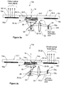
- Figures 2a and 2b show examples among others of schematic representations (cross sectional views) of a stereoscopic optical device (display) 10 (or an EPE device) with a flat diffractive exit pupil expander 12 (e.g., a one-piece substrate) using sequential switching between a right image 32-1d ( Figure 2a ) and a left image 32-2d ( Figure 2b ) of a microdisplay 24 , according to an embodiment of the present invention.
- the microdisplay 24 in this example can utilize, e.g., a liquid crystal on silicon (LCOS).
- LCOS liquid crystal on silicon
- the EPE 12 is a solid substrate comprising two adjacent areas 12a and 12b that are adjacent to each other along a line 18 (here line 18 is an imaginary line).
- the area 12a comprises the in-coupling grating 14a and an out-coupling grating 16a and the area 12b comprises the in-coupling grating 14b and an out-coupling grating 16b , respectively.
- the adjacent gratings 14a and 14b can be highly asymmetric as further shown in an example of Figure 4a .
- the optical delivery system is configured to sequentially switch the two input optical beams comprising the optical image of the microdisplay 24 between the two diffractive elements 14a and 14b.
- the optical delivery system can comprise two optical sources (e.g., light emitting diodes) 20a and 20b which can be combined in a dual light source 20 , configured to provide two optical beams 32-1 and 32-2 (typically polarized) in substantially different directions as shown in Figures 2a and 2b , respectively, for sequentially switching the two input optical beams 32-1b and 32-2b comprising images of the microdisplay 24 which are diffracted to the corresponding optical beams 32-1c and 32-2c by the in-coupling gratings 14a and 14b and further diffracted to the optical output beams (the right and the left images of the microdisplay 30 ) 32-1d and 32-2d , wherein the two optical sources 20a and 20b are configured to turn on and off in a sequential manner with the predetermined period as discussed above
- the optical delivery system e.g., for an LCOS microdisplay 24 can further comprise a wire grid polarizer 26 configured as a polarization beam-splitter to redirect two optical beams reflected for sequentially switching the two input optical beams between said two diffractive elements (see Examples in Figures 2a, 2b , 3a and 3b ).
- a traditional 50% beam splitter can be also utilized which will result in more than 75% optical power loss, therefore using the wire grid polarizer which minimizes the optical power loss to a minimum (typically less than 20%) is advantageous.
- the wire grid polarizer is known in the art and described, e.g., by S. Arnold, E. Gardner, D. Hansen and R. Perkins in "An improved polarizing beamsplitter LCOS Projection Display Based on Wire-Grid Polarizers", SID 01 Digest, Paper 52.3, page 1282-1285 (2001 ).
- the optical delivery system may comprise a shutter 30 configured to sequentially switch the two input optical beams 32-1b and 32-2b between the two diffractive elements 14a and 14b with the predetermined period: a) in addition to turning on and off the light sources 20a and 20b for improving the separation of the left and right input optical beams 32-1b and 32-2b or b) instead of turning on and off the light sources 20a and 20b thus simplifying the illumination optics.
- Figures 3a and 3b show examples among others of schematic representations (cross sectional views) of a stereoscopic optical device (display) 10a with a split diffractive exit pupil expander (EPE) 12-1 using sequential switching between the right image 32-1d ( Figure 3a ) and the left image 32-2d ( Figure 3b ) of the LCOS microdisplay 24 , according to an embodiment of the present invention.
- the only difference in Figures 3a and 3b compared to Figures 2a and 2b , is using the split EPE comprising physically separated areas 12a and 12b and physically separated input diffraction gratings 14a and 14b, respectively.
- split input diffraction gratings 14a and 14b can provide better optical isolation between the areas 12a and 12b and better separation of the images 32-1d and 32-2d.
- this split substrate 12-1 can be configured that the first and the second areas 12a and 12b can rotate relative to each around the line 18 in a predetermined angle range (in a direction 15 as shown in figures 3a and 3b ) to provide better viewing if required.
- Figure 4a shows one example among others of a schematic representation of slanted asymmetric gratings 14a and 14b (which can be considered as one diffraction grating 14 ) used in the exit pupil expander 12 (with one-piece substrate) of a stereoscopic optical display 10 shown in Figures 2a and 2b , according to an embodiment of the present invention.
- the optical contrast can be further improved by providing an absorbing material (e.g., an absorbing coating) 17 on a surface of the substrate 12 opposite to the substrate surface with the disposed input diffraction gratings 14a and 14b in a vicinity of the line 18 (as shown in Figure 4a ).
- an absorbing material e.g., an absorbing coating
- the width of the absorbing area is optimized to be small enough compared to the total width of the gratings 14a and 14b as shown in Figure 4a , only the unwanted optical beams will be absorbed. These unwanted beams are the optical beams which are transmitted by the gratings 14a and 14b without diffracting and those diffracted beams that propagate in unwanted directions.
- Figure 4b shows one further example among others of a schematic representation of a split exit pupil expander 12-1 of a stereoscopic optical display 10a shown in Figures 3a and 3b using split slanted asymmetric in-coupling gratings 14a and 14b (diffractions grooves of gratings 14a and 14b face different directions relative to the optical axis of the system providing input optical beams), according to an embodiment of the present invention.
- the ends of the diffraction gratings 14a and 14b can be coated with an absorbing material 20a and 20b along the line 18 to further optically isolate the areas 12a and 12b.
- the absorbing materials 17a and 17b can be used in addition or instead of absorbing material 20a and 20b to further improve the optical contrast.
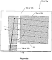
- Figures 5a and 5b show further examples among others of schematic representations (cross-sectional views) of one area out of two areas 12a or 12b of a two-dimensional diffractive exit pupil expander 12 or 12-1 , according to an embodiment of the present invention.
- An intermediate diffractive element (diffraction grating) 24 or 26 has odd number of first order diffractions (shown in Figure 4a ) or even number of further first order reflections (shown in Figure 4b ) as described by T.
- the angle ⁇ is a rotation angle between the periodic lines of the intermediate diffraction grating 26 and the in-coupling grating 14a or 14b.
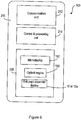
- Figure 6 shows an example of a schematic representation of an electronic device, having a stereoscopic display 10 or 10a with the exit pupil expander (EPE) 12 , according to an embodiment of the present invention.
- EPE exit pupil expander
- the exit pupil expander (EPE) 12 or 12-1 can be used in an electronic (portable) device 100 , such as a mobile phone, personal digital assistant (PDA), communicator, portable Internet appliance, hand-hand computer, digital video and still camera, wearable computer, computer game device, specialized bring-to-the-eye product for viewing and other portable electronic devices.
- the portable device 100 has a housing 210 to house a communication unit 212 for receiving and transmitting information from and to an external device (not shown).
- the portable device 100 also has a controlling and processing unit 214 for handling the received and transmitted information, and a virtual display system 230 for viewing.
- the virtual display system 230 includes a micro-display or an image source 192 and an optical engine 190.
- the controlling and processing unit 214 is operatively connected to the optical engine 190 to provide image data to the image source 192 to display an image thereon.
- the EPE device 10 or 10a can be optically linked to an optical engine 190.
- the image source 192 can be a sequential color LCOS (Liquid Crystal On Silicon) device, an OLED (Organic Light Emitting Diode) array, an MEMS (MicroElectro Mechanical System) device or any other suitable micro-display device operating in transmission, reflection or emission.
- LCOS Liquid Crystal On Silicon
- OLED Organic Light Emitting Diode
- MEMS MicroElectro Mechanical System
- the electronic device 100 can be a portable device, such as a mobile phone, personal digital assistant (PDA), communicator, portable Internet appliance, hand-held computer, digital video and still camera, wearable computer, computer game device, specialized bring-to-the-eye product for viewing and other portable electronic devices.
- PDA personal digital assistant
- the exit pupil expander can also be used in a non-portable device, such as a gaming device, vending machine, band-o-matic, and home appliances, such as an oven, microwave oven and other appliances and other non-portable devices.
Landscapes
- Physics & Mathematics (AREA)
- General Physics & Mathematics (AREA)
- Optics & Photonics (AREA)
- Diffracting Gratings Or Hologram Optical Elements (AREA)
Claims (14)
- Vorrichtung (10), umfassend:ein Substrat (12) aus optischem Material mit einer ersten Oberfläche und einer zweiten Oberfläche, wobei das Substrat einen ersten Bereich (12a) und einen zweiten Bereich (12b) umfasst, die im Wesentlichen entlang einer Linie (18) nebeneinander liegen;zwei auf der ersten oder der zweiten Oberfläche angeordnete Beugungsmittel (14a, 14b), die konfiguriert sind, jeweils zwei sequentiell geschaltete optische Eingangsstrahlen (32-1b, 32-2b) zu empfangen, die ein optisches Bild einer Anzeige (24) umfassen, so dass einer der zwei sequentiell geschalteten optischen Eingangsstrahlen (32-1b) von nur einem der zwei Beugungsmittel empfangen wird und ein anderer der zwei sequentiell geschalteten optischen Eingangsstrahlen (32-2b) von nur einem anderen der zwei Beugungsmittel (14b) empfangen wird, wobei eines der beiden Beugungsmittel (14a) auf der ersten Fläche angeordnet ist und ein anderes der beiden Beugungsmittel auf der zweiten Fläche angeordnet ist, wobei die beiden Beugungsmittel (14a, 14b) im Wesentlichen nebeneinander und benachbart zu der Linie (18) sind;
zwei weitere auf der ersten oder der zweiten Oberfläche angeordnete Beugungsmittel (16a, 16b), wobei eines der beiden weiteren Beugungsmittel (16a) auf dem ersten Bereich (12a) angeordnet ist und ein anderes der beiden weiteren Beugungsmittel (16b) auf dem zweiten Bereich (12b) angeordnet ist; undMittel zur optischen Abgabe (20, 22, 24, 26, 28), die konfiguriert sind, die zwei optischen Eingangsstrahlen (32-1b, 32-2b), die das optische Bild der Anzeige (24) umfassen, zwischen den beiden Beugungsmitteln (14a, 14b) zu schalten;wobei die Vorrichtung so konfiguriert ist, dass:mindestens ein Teil jedes der beiden sequentiell geschalteten optischen Eingangsstrahlen (32-1b, 32-2b) zu jedem Zeitpunkt nur in einem der beiden Beugungsmittel (14a, 14b) gebeugt wird, um einen gebeugten optischen Strahl (32-1c) im gleichen Bereich mit dem einen der beiden Beugungsmittel im Wesentlichen innerhalb der ersten und zweiten Oberfläche bereitzustellen, undmindestens ein Teil des gebeugten optischen Strahls (32-1c) in dem ersten oder zweiten Bereich (12a, 12b) durch Beugung in einem der beiden weiteren Beugungsmittel (16a, 16b) aus dem Substrat (12) zum Bereitstellen von zwei sequentiell geschalteten und im Wesentlichen identischen optischen Ausgangsstrahlen (32-1d, 32-2d) ausgekoppelt wird, von denen jeder das optische Bild der Anzeige (24) mit einer erweiterten Austrittspupille in einer oder zwei Dimensionen umfasst. - Vorrichtung (10) nach Anspruch 1, wobei die zwei sequentiell geschalteten und im Wesentlichen identischen optischen Ausgangsstrahlen (32-1b, 32-2b) zur Erzeugung eines stereoskopischen Bildes der Anzeige (24) dienen.
- Vorrichtung (10) nach Anspruch 1, wobei das Mittel zur optischen Abgabe (20, 22, 24, 26, 28, 30) zwei optische Quellen (20a, 20b) umfasst, die konfiguriert sind, zwei optische Strahlen (32-1, 32-2) in im Wesentlichen verschiedenen Richtungen zum sequentiellen Schalten der beiden optischen Eingangsstrahlen (32-1b, 32-2b) bereitzustellen.
- Vorrichtung (10) nach Anspruch 3, wobei das Mittel zur optischen Abgabe (20, 22, 24, 26, 28, 30) einen Drahtgitterpolarisator (26) aufweist, der als Strahlteiler konfiguriert ist, um die beiden optischen Strahlen (32-1, 32-2) zum sequentiellen Umschalten der beiden optischen Eingangsstrahlen (32-1b, 32-2b) zwischen den beiden Beugungsmitteln (14a, 14b) umzulenken und die Anzeige (24) ein Liquid-Crystal-on-Silicon-Display ist.
- Vorrichtung (10) nach Anspruch 1, wobei das Mittel zur optischen Abgabe (20, 22, 24, 26, 28, 30) eine Blende (30) umfasst, der zum sequentiellen Schalten der beiden optischen Eingangsstrahlen (32-1b, 32-2b) zwischen den beiden Beugungsmitteln (14a, 14b) mit einer vorgegebenen Periode konfiguriert ist.
- Vorrichtung (10) nach Anspruch 1, wobei das Substrat (12) ein einstückiges Substrat ist.
- Vorrichtung (10) nach Anspruch 1, wobei das Substrat (12) konfiguriert ist, in der Nähe der Linie (18) ein absorbierendes Material (17) auf einer Oberfläche des Substrats zu haben, die einer Substratoberfläche mit den zwei angeordneten Beugungsmitteln (14a, 14b) gegenüberliegt.
- Vorrichtung (10) nach Anspruch 1, wobei das Substrat (12) ein geteiltes Substrat ist, so dass der erste Bereich (12a) und der zweite Bereich (12b) physikalisch getrennt sind.
- Vorrichtung (10) nach Anspruch 8, wobei ein absorbierendes Material (20a, 20b) an einem Ende des ersten und/oder des zweiten Teils in einem Bereich ihrer physikalischen Trennung entlang der Linie (18) abgelagert ist.
- Vorrichtung (10) nach Anspruch 1, wobei die beiden Beugungsmittel (14a, 14b) eine asymmetrische Rillenform aufweisen, so dass der optische Eingangsstrahl (32-1b, 32-2b) von jedem der beiden Beugungsmittel im Wesentlichen nur an einen Bereich außerhalb des ersten und des zweiten Bereichs (12a, 12b) gekoppelt ist, in dem die beiden Beugungsmittel angeordnet sind.
- Vorrichtung (10) nach Anspruch 1, wobei die beiden Beugungsmittel (14a, 14b) eine asymmetrische Rillenform aufweisen und geneigte Gitter mit einem Neigungswinkel von mehr als 20 Grad sind.
- Vorrichtung (10) nach Anspruch 1, wobei die beiden Beugungsmittel (14a, 14b) asymmetrisch sind, so dass ihre Rillenformen Spiegelbilder voneinander in Bezug auf die Linie (18) sind, die die ersten und die zweiten Bereiche (12a, 12b) trennt.
- Verfahren, umfassend:Empfangen von zwei sequentiell geschalteten optischen Eingangsstrahlen (32-1b, 32-2b) durch zwei Beugungsmittel (14a, 14b) derart, dass einer der beiden optischen Eingangsstrahlen (32-1b) durch nur eines der beiden Beugungsmittel (14a) und ein anderer der beiden optischen Eingangsstrahlen (32-2b) nur von einem anderen der beiden Beugungsmittel (14b) empfangen wird, wobei die beiden Beugungsmittel (14a, 14b) auf einer ersten oder einer zweiten Oberfläche eines Substrats (12) aus optischem Material angeordnet sind, wobei das Substrat einen ersten Bereich (12a) und einen zweiten Bereich (12b) aufweist, die im Wesentlichen entlang einer Linie (18) nebeneinander liegen, wobei das eine der beiden Beugungsmittel (14a) auf dem ersten Bereich (12a) angeordnet ist und das andere der beiden Beugungsmittel (14b) auf dem zweiten Bereich (12b) angeordnet ist, wobei die beiden Beugungsmittel (14a, 14b) im Wesentlichen nebeneinander und benachbart zu der Linie (18) liegen, wobei die zwei sequentiell geschalteten optischen Eingangsstrahlen (32-1b, 32-2b) ein optisches Bild einer Anzeige (24) umfassen und von einem Mittel zur optischen Abgabe (20, 22, 24, 26, 28, 30) bereitgestellt werden;Beugen mindestens eines Teils jedes der beiden sequentiell geschalteten optischen Eingangsstrahlen (32-1b, 32-1c) zu jedem Zeitpunkt nur in einem der beiden Beugungsmittel (14a, 14b), um einen gebeugten optischen Strahl (32-1c) im gleichen Bereich mit dem einen der beiden Beugungsmittel (14a, 14b) im Wesentlichen innerhalb der ersten und zweiten Oberfläche bereitzustellen; undAuskoppeln zumindest eines Teils des gebeugten optischen Strahls (32-1c) in den ersten oder den zweiten Bereich (12a, 12b) aus dem Substrat (12) durch Beugung in einem von zwei weiteren Beugungsmitteln (16a, 16b) zur Bereitstellung zweier sequentiell geschalteter und im Wesentlichen identischer optischer Ausgangsstrahlen (32-1d, 32-2d), von denen jeder das optische Bild der Anzeige (24) mit einer erweiterten Austrittspupille in einer oder zwei Dimensionen umfasst,wobei die zwei weiteren Beugungsmittel (16a, 16b) auf der ersten oder der zweiten Oberfläche angeordnet sind, wobei eines der zwei weiteren Beugungsmittel (16a) auf dem ersten Bereich (12a) angeordnet ist und ein anderes der zwei weiteren Mittel zur Beugung (16b) auf dem zweiten Bereich (12b) angeordnet ist.
- Elektronisches Gerät (100), umfassend:- eine Datenverarbeitungseinheit (214);
eine optische Maschine (190) zum Empfangen von Bilddaten von der Datenverarbeitungseinheit;- eine Anzeigevorrichtung (192) zum Erzeugen eines Bildes basierend auf den Bilddaten; und- eine Austrittspupillenerweiterungsvorrichtung (10a) mit der Vorrichtung (10) nach einem der vorhergehenden Ansprüche 1 bis 12.
Priority Applications (1)
| Application Number | Priority Date | Filing Date | Title |
|---|---|---|---|
| EP20154750.2A EP3683616B1 (de) | 2006-06-02 | 2006-06-02 | Stereoskopische austrittspupillen-expander-anzeige |
Applications Claiming Priority (1)
| Application Number | Priority Date | Filing Date | Title |
|---|---|---|---|
| PCT/IB2006/001472 WO2007141589A1 (en) | 2006-06-02 | 2006-06-02 | Stereoscopic exit pupil expander display |
Related Child Applications (2)
| Application Number | Title | Priority Date | Filing Date |
|---|---|---|---|
| EP20154750.2A Division EP3683616B1 (de) | 2006-06-02 | 2006-06-02 | Stereoskopische austrittspupillen-expander-anzeige |
| EP20154750.2A Division-Into EP3683616B1 (de) | 2006-06-02 | 2006-06-02 | Stereoskopische austrittspupillen-expander-anzeige |
Publications (3)
| Publication Number | Publication Date |
|---|---|
| EP2033040A1 EP2033040A1 (de) | 2009-03-11 |
| EP2033040A4 EP2033040A4 (de) | 2012-07-18 |
| EP2033040B1 true EP2033040B1 (de) | 2020-04-29 |
Family
ID=38801097
Family Applications (2)
| Application Number | Title | Priority Date | Filing Date |
|---|---|---|---|
| EP20154750.2A Active EP3683616B1 (de) | 2006-06-02 | 2006-06-02 | Stereoskopische austrittspupillen-expander-anzeige |
| EP06765457.4A Active EP2033040B1 (de) | 2006-06-02 | 2006-06-02 | Stereoskopisches ausgangspupillenexpandiererdisplay |
Family Applications Before (1)
| Application Number | Title | Priority Date | Filing Date |
|---|---|---|---|
| EP20154750.2A Active EP3683616B1 (de) | 2006-06-02 | 2006-06-02 | Stereoskopische austrittspupillen-expander-anzeige |
Country Status (4)
| Country | Link |
|---|---|
| US (1) | US8466953B2 (de) |
| EP (2) | EP3683616B1 (de) |
| CN (1) | CN101460883B (de) |
| WO (1) | WO2007141589A1 (de) |
Families Citing this family (151)
| Publication number | Priority date | Publication date | Assignee | Title |
|---|---|---|---|---|
| US7205960B2 (en) | 2003-02-19 | 2007-04-17 | Mirage Innovations Ltd. | Chromatic planar optic display system |
| GB0522968D0 (en) | 2005-11-11 | 2005-12-21 | Popovich Milan M | Holographic illumination device |
| GB0718706D0 (en) | 2007-09-25 | 2007-11-07 | Creative Physics Ltd | Method and apparatus for reducing laser speckle |
| WO2008071830A1 (en) * | 2006-12-14 | 2008-06-19 | Nokia Corporation | Display device having two operating modes |
| DE102007021036A1 (de) | 2007-05-04 | 2008-11-06 | Carl Zeiss Ag | Anzeigevorrichtung und Anzeigeverfahren zur binokularen Darstellung eines mehrfarbigen Bildes |
| US20100302644A1 (en) * | 2007-09-18 | 2010-12-02 | Mirage Innovations Ltd | Slanted optical device |
| US8830584B2 (en) | 2007-12-17 | 2014-09-09 | Nokia Corporation | Exit pupil expanders with spherical and aspheric substrates |
| US8508848B2 (en) | 2007-12-18 | 2013-08-13 | Nokia Corporation | Exit pupil expanders with wide field-of-view |
| US9335604B2 (en) | 2013-12-11 | 2016-05-10 | Milan Momcilo Popovich | Holographic waveguide display |
| US11726332B2 (en) | 2009-04-27 | 2023-08-15 | Digilens Inc. | Diffractive projection apparatus |
| US11320571B2 (en) | 2012-11-16 | 2022-05-03 | Rockwell Collins, Inc. | Transparent waveguide display providing upper and lower fields of view with uniform light extraction |
| US10795160B1 (en) | 2014-09-25 | 2020-10-06 | Rockwell Collins, Inc. | Systems for and methods of using fold gratings for dual axis expansion |
| US8233204B1 (en) | 2009-09-30 | 2012-07-31 | Rockwell Collins, Inc. | Optical displays |
| US11300795B1 (en) | 2009-09-30 | 2022-04-12 | Digilens Inc. | Systems for and methods of using fold gratings coordinated with output couplers for dual axis expansion |
| US20200057353A1 (en) | 2009-10-09 | 2020-02-20 | Digilens Inc. | Compact Edge Illuminated Diffractive Display |
| US11204540B2 (en) | 2009-10-09 | 2021-12-21 | Digilens Inc. | Diffractive waveguide providing a retinal image |
| US8659826B1 (en) | 2010-02-04 | 2014-02-25 | Rockwell Collins, Inc. | Worn display system and method without requiring real time tracking for boresight precision |
| US9274349B2 (en) | 2011-04-07 | 2016-03-01 | Digilens Inc. | Laser despeckler based on angular diversity |
| WO2016020630A2 (en) | 2014-08-08 | 2016-02-11 | Milan Momcilo Popovich | Waveguide laser illuminator incorporating a despeckler |
| EP2748670B1 (de) | 2011-08-24 | 2015-11-18 | Rockwell Collins, Inc. | Tragbare datenanzeige |
| US10670876B2 (en) | 2011-08-24 | 2020-06-02 | Digilens Inc. | Waveguide laser illuminator incorporating a despeckler |
| US9715067B1 (en) | 2011-09-30 | 2017-07-25 | Rockwell Collins, Inc. | Ultra-compact HUD utilizing waveguide pupil expander with surface relief gratings in high refractive index materials |
| US9507150B1 (en) | 2011-09-30 | 2016-11-29 | Rockwell Collins, Inc. | Head up display (HUD) using a bent waveguide assembly |
| US9366864B1 (en) | 2011-09-30 | 2016-06-14 | Rockwell Collins, Inc. | System for and method of displaying information without need for a combiner alignment detector |
| US8634139B1 (en) | 2011-09-30 | 2014-01-21 | Rockwell Collins, Inc. | System for and method of catadioptric collimation in a compact head up display (HUD) |
| US20150010265A1 (en) | 2012-01-06 | 2015-01-08 | Milan, Momcilo POPOVICH | Contact image sensor using switchable bragg gratings |
| US9523852B1 (en) | 2012-03-28 | 2016-12-20 | Rockwell Collins, Inc. | Micro collimator system and method for a head up display (HUD) |
| EP2842003B1 (de) | 2012-04-25 | 2019-02-27 | Rockwell Collins, Inc. | Holographisches weitwinkeldisplay |
| US10627623B2 (en) | 2012-05-03 | 2020-04-21 | Nokia Technologies Oy | Image providing apparatus, method and computer program |
| US9456744B2 (en) | 2012-05-11 | 2016-10-04 | Digilens, Inc. | Apparatus for eye tracking |
| CN104704423A (zh) * | 2012-10-05 | 2015-06-10 | 诺基亚技术有限公司 | 用于捕获图像的装置和方法 |
| EP2720072A1 (de) | 2012-10-12 | 2014-04-16 | Vision Engineering Limited | Optisches Instrument mit diffraktivem Element |
| US9933684B2 (en) | 2012-11-16 | 2018-04-03 | Rockwell Collins, Inc. | Transparent waveguide display providing upper and lower fields of view having a specific light output aperture configuration |
| US20140168260A1 (en) * | 2012-12-13 | 2014-06-19 | Paul M. O'Brien | Waveguide spacers within an ned device |
| JP6197295B2 (ja) | 2013-01-22 | 2017-09-20 | セイコーエプソン株式会社 | 光学デバイス及び画像表示装置 |
| US9674413B1 (en) | 2013-04-17 | 2017-06-06 | Rockwell Collins, Inc. | Vision system and method having improved performance and solar mitigation |
| US9086568B2 (en) | 2013-04-18 | 2015-07-21 | Nokia Technologies Oy | Method and apparatus for view recovery |
| US10209517B2 (en) | 2013-05-20 | 2019-02-19 | Digilens, Inc. | Holographic waveguide eye tracker |
| US9727772B2 (en) | 2013-07-31 | 2017-08-08 | Digilens, Inc. | Method and apparatus for contact image sensing |
| US9244281B1 (en) | 2013-09-26 | 2016-01-26 | Rockwell Collins, Inc. | Display system and method using a detached combiner |
| KR102202454B1 (ko) * | 2013-11-29 | 2021-01-14 | 엘지디스플레이 주식회사 | 박막형 시야 범위 조절 백 라이트 유닛 및 이를 이용한 박막 평판형 시야 범위 조절 표시장치 |
| US10732407B1 (en) | 2014-01-10 | 2020-08-04 | Rockwell Collins, Inc. | Near eye head up display system and method with fixed combiner |
| US9519089B1 (en) | 2014-01-30 | 2016-12-13 | Rockwell Collins, Inc. | High performance volume phase gratings |
| US9244280B1 (en) | 2014-03-25 | 2016-01-26 | Rockwell Collins, Inc. | Near eye display system and method for display enhancement or redundancy |
| JP2015194550A (ja) * | 2014-03-31 | 2015-11-05 | セイコーエプソン株式会社 | 光学デバイス、画像投影装置及び電子機器 |
| US9529196B1 (en) | 2014-06-05 | 2016-12-27 | Iphysicist Ltd. | Image guide optics for near eye displays |
| US10254942B2 (en) | 2014-07-31 | 2019-04-09 | Microsoft Technology Licensing, Llc | Adaptive sizing and positioning of application windows |
| US10678412B2 (en) | 2014-07-31 | 2020-06-09 | Microsoft Technology Licensing, Llc | Dynamic joint dividers for application windows |
| US10592080B2 (en) | 2014-07-31 | 2020-03-17 | Microsoft Technology Licensing, Llc | Assisted presentation of application windows |
| WO2016020632A1 (en) | 2014-08-08 | 2016-02-11 | Milan Momcilo Popovich | Method for holographic mastering and replication |
| WO2016042283A1 (en) | 2014-09-19 | 2016-03-24 | Milan Momcilo Popovich | Method and apparatus for generating input images for holographic waveguide displays |
| US10088675B1 (en) | 2015-05-18 | 2018-10-02 | Rockwell Collins, Inc. | Turning light pipe for a pupil expansion system and method |
| US9715110B1 (en) | 2014-09-25 | 2017-07-25 | Rockwell Collins, Inc. | Automotive head up display (HUD) |
| EP3198192A1 (de) | 2014-09-26 | 2017-08-02 | Milan Momcilo Popovich | Optischer tracker mit holografischem wellenleiter |
| AU2015323940B2 (en) * | 2014-09-29 | 2021-05-20 | Magic Leap, Inc. | Architectures and methods for outputting different wavelength light out of waveguides |
| US9659410B2 (en) * | 2014-10-21 | 2017-05-23 | Honeywell International Inc. | Low latency augmented reality display |
| US10437064B2 (en) | 2015-01-12 | 2019-10-08 | Digilens Inc. | Environmentally isolated waveguide display |
| EP3245551B1 (de) | 2015-01-12 | 2019-09-18 | DigiLens Inc. | Lichtfeldanzeigen mit wellenleiter |
| CN107533137A (zh) | 2015-01-20 | 2018-01-02 | 迪吉伦斯公司 | 全息波导激光雷达 |
| US10018844B2 (en) | 2015-02-09 | 2018-07-10 | Microsoft Technology Licensing, Llc | Wearable image display system |
| US9429692B1 (en) | 2015-02-09 | 2016-08-30 | Microsoft Technology Licensing, Llc | Optical components |
| US9513480B2 (en) | 2015-02-09 | 2016-12-06 | Microsoft Technology Licensing, Llc | Waveguide |
| US10317677B2 (en) | 2015-02-09 | 2019-06-11 | Microsoft Technology Licensing, Llc | Display system |
| US9372347B1 (en) * | 2015-02-09 | 2016-06-21 | Microsoft Technology Licensing, Llc | Display system |
| US9535253B2 (en) | 2015-02-09 | 2017-01-03 | Microsoft Technology Licensing, Llc | Display system |
| US9827209B2 (en) | 2015-02-09 | 2017-11-28 | Microsoft Technology Licensing, Llc | Display system |
| US11086216B2 (en) | 2015-02-09 | 2021-08-10 | Microsoft Technology Licensing, Llc | Generating electronic components |
| US9632226B2 (en) | 2015-02-12 | 2017-04-25 | Digilens Inc. | Waveguide grating device |
| CN108351519A (zh) * | 2015-02-17 | 2018-07-31 | 赛尔米克实验室公司 | 用于在可穿戴式平视显示器中进行适眼区扩大的系统、设备和方法 |
| WO2016146963A1 (en) | 2015-03-16 | 2016-09-22 | Popovich, Milan, Momcilo | Waveguide device incorporating a light pipe |
| US10591756B2 (en) | 2015-03-31 | 2020-03-17 | Digilens Inc. | Method and apparatus for contact image sensing |
| US10126552B2 (en) | 2015-05-18 | 2018-11-13 | Rockwell Collins, Inc. | Micro collimator system and method for a head up display (HUD) |
| US10247943B1 (en) | 2015-05-18 | 2019-04-02 | Rockwell Collins, Inc. | Head up display (HUD) using a light pipe |
| US11366316B2 (en) | 2015-05-18 | 2022-06-21 | Rockwell Collins, Inc. | Head up display (HUD) using a light pipe |
| US10108010B2 (en) | 2015-06-29 | 2018-10-23 | Rockwell Collins, Inc. | System for and method of integrating head up displays and head down displays |
| US9910276B2 (en) | 2015-06-30 | 2018-03-06 | Microsoft Technology Licensing, Llc | Diffractive optical elements with graded edges |
| US10670862B2 (en) | 2015-07-02 | 2020-06-02 | Microsoft Technology Licensing, Llc | Diffractive optical elements with asymmetric profiles |
| US10038840B2 (en) | 2015-07-30 | 2018-07-31 | Microsoft Technology Licensing, Llc | Diffractive optical element using crossed grating for pupil expansion |
| US9864208B2 (en) * | 2015-07-30 | 2018-01-09 | Microsoft Technology Licensing, Llc | Diffractive optical elements with varying direction for depth modulation |
| US10073278B2 (en) * | 2015-08-27 | 2018-09-11 | Microsoft Technology Licensing, Llc | Diffractive optical element using polarization rotation grating for in-coupling |
| WO2017060665A1 (en) | 2015-10-05 | 2017-04-13 | Milan Momcilo Popovich | Waveguide display |
| US10429645B2 (en) | 2015-10-07 | 2019-10-01 | Microsoft Technology Licensing, Llc | Diffractive optical element with integrated in-coupling, exit pupil expansion, and out-coupling |
| US10241332B2 (en) | 2015-10-08 | 2019-03-26 | Microsoft Technology Licensing, Llc | Reducing stray light transmission in near eye display using resonant grating filter |
| US9946072B2 (en) * | 2015-10-29 | 2018-04-17 | Microsoft Technology Licensing, Llc | Diffractive optical element with uncoupled grating structures |
| US10234686B2 (en) | 2015-11-16 | 2019-03-19 | Microsoft Technology Licensing, Llc | Rainbow removal in near-eye display using polarization-sensitive grating |
| US10598932B1 (en) | 2016-01-06 | 2020-03-24 | Rockwell Collins, Inc. | Head up display for integrating views of conformally mapped symbols and a fixed image source |
| EP3398007B1 (de) | 2016-02-04 | 2024-09-11 | DigiLens, Inc. | Optischer wellenleitertracker |
| JP6895451B2 (ja) | 2016-03-24 | 2021-06-30 | ディジレンズ インコーポレイテッド | 偏光選択ホログラフィー導波管デバイスを提供するための方法および装置 |
| EP3433658B1 (de) | 2016-04-11 | 2023-08-09 | DigiLens, Inc. | Holographische wellenleitervorrichtung für die projektion von strukturiertem licht |
| US10067347B2 (en) | 2016-04-13 | 2018-09-04 | Microsoft Technology Licensing, Llc | Waveguides with improved intensity distributions |
| US9791703B1 (en) | 2016-04-13 | 2017-10-17 | Microsoft Technology Licensing, Llc | Waveguides with extended field of view |
| US10353202B2 (en) * | 2016-06-09 | 2019-07-16 | Microsoft Technology Licensing, Llc | Wrapped waveguide with large field of view |
| US10025170B2 (en) * | 2016-06-13 | 2018-07-17 | Microsoft Technology Licensing, Llc | Avoiding interference by reducing spatial coherence in a near-eye display |
| US10095045B2 (en) | 2016-09-12 | 2018-10-09 | Microsoft Technology Licensing, Llc | Waveguide comprising a bragg polarization grating |
| IL312713A (en) * | 2016-11-18 | 2024-07-01 | Magic Leap Inc | Waveguide light multiplexer using crossed gratings |
| EP3548939A4 (de) | 2016-12-02 | 2020-11-25 | DigiLens Inc. | Wellenleitervorrichtung mit gleichmässiger ausgabebeleuchtung |
| CN114442315B (zh) * | 2016-12-12 | 2025-06-24 | 元平台技术有限公司 | 平铺波导显示器 |
| US10545346B2 (en) | 2017-01-05 | 2020-01-28 | Digilens Inc. | Wearable heads up displays |
| US10108014B2 (en) * | 2017-01-10 | 2018-10-23 | Microsoft Technology Licensing, Llc | Waveguide display with multiple focal depths |
| AU2018210527B2 (en) | 2017-01-23 | 2022-12-01 | Magic Leap, Inc. | Eyepiece for virtual, augmented, or mixed reality systems |
| US10295824B2 (en) | 2017-01-26 | 2019-05-21 | Rockwell Collins, Inc. | Head up display with an angled light pipe |
| EP3583351B1 (de) | 2017-02-14 | 2023-12-13 | Snap Inc. | Wellenleiterstruktur |
| JP2020514802A (ja) | 2017-03-14 | 2020-05-21 | マジック リープ, インコーポレイテッドMagic Leap,Inc. | 吸光膜を有する導波管およびそれを形成するためのプロセス |
| KR102720048B1 (ko) * | 2017-03-22 | 2024-10-18 | 매직 립, 인코포레이티드 | 합성 시야를 활용하는 웨어러블 디스플레이 디바이스 |
| CN106908953A (zh) * | 2017-03-28 | 2017-06-30 | 陈超平 | 一种集成视力矫正的双目近眼显示装置 |
| US10281726B2 (en) * | 2017-04-04 | 2019-05-07 | Microsoft Technology Licensing, Llc | Refractive-diffractive display system with wide field of view |
| US10969585B2 (en) | 2017-04-06 | 2021-04-06 | Microsoft Technology Licensing, Llc | Waveguide display with increased uniformity and reduced cross-coupling between colors |
| FI128831B (en) * | 2017-05-03 | 2021-01-15 | Dispelix Oy | Display element, personal display unit, procedure for producing an image on a personal display and use |
| FI128413B (en) | 2017-06-02 | 2020-04-30 | Dispelix Oy | Diffractive element with double period lattices |
| CN111386495B (zh) | 2017-10-16 | 2022-12-09 | 迪吉伦斯公司 | 用于倍增像素化显示器的图像分辨率的系统和方法 |
| CN107797287A (zh) * | 2017-11-28 | 2018-03-13 | 苏州苏大维格光电科技股份有限公司 | 光波导镜片及显示装置 |
| CA3084011C (en) | 2017-12-15 | 2024-06-11 | Magic Leap, Inc. | Eyepieces for augmented reality display system |
| CN114721242B (zh) | 2018-01-08 | 2025-08-15 | 迪吉伦斯公司 | 用于制造光学波导的方法 |
| WO2019136476A1 (en) | 2018-01-08 | 2019-07-11 | Digilens, Inc. | Waveguide architectures and related methods of manufacturing |
| JP7456929B2 (ja) | 2018-01-08 | 2024-03-27 | ディジレンズ インコーポレイテッド | 導波管セルを製造するためのシステムおよび方法 |
| JP7404243B2 (ja) | 2018-01-08 | 2023-12-25 | ディジレンズ インコーポレイテッド | 導波管セル内のホログラフィック格子の高スループット記録のためのシステムおよび方法 |
| US10690851B2 (en) | 2018-03-16 | 2020-06-23 | Digilens Inc. | Holographic waveguides incorporating birefringence control and methods for their fabrication |
| EP3762762B1 (de) | 2018-04-03 | 2023-05-31 | Huawei Technologies Co., Ltd. | Anzeigevorrichtung für kopfmontage und anzeigeverfahren |
| US11402801B2 (en) | 2018-07-25 | 2022-08-02 | Digilens Inc. | Systems and methods for fabricating a multilayer optical structure |
| US11209644B1 (en) | 2018-08-10 | 2021-12-28 | Facebook Technologies, Llc | Pupil steering for a pupil expander |
| US11914148B2 (en) | 2018-09-07 | 2024-02-27 | Adeia Semiconductor Inc. | Stacked optical waveguides |
| US11103763B2 (en) | 2018-09-11 | 2021-08-31 | Real Shot Inc. | Basketball shooting game using smart glasses |
| US11141645B2 (en) | 2018-09-11 | 2021-10-12 | Real Shot Inc. | Athletic ball game using smart glasses |
| EP3857293B1 (de) * | 2018-09-28 | 2024-04-17 | Magic Leap, Inc. | Projektionssystem mit kollimierendem abtastendem spiegel |
| WO2020106824A1 (en) | 2018-11-20 | 2020-05-28 | Magic Leap, Inc. | Eyepieces for augmented reality display system |
| TWI826899B (zh) | 2018-12-17 | 2023-12-21 | 美商應用材料股份有限公司 | 使用電子束裝置進行的光學元件製造方法 |
| JP7483711B2 (ja) * | 2018-12-17 | 2024-05-15 | アプライド マテリアルズ インコーポレイテッド | 格子を形成する方法 |
| US11914150B2 (en) | 2018-12-28 | 2024-02-27 | Magic Leap, Inc. | Augmented and virtual reality display systems with shared display for left and right eyes |
| WO2020149956A1 (en) | 2019-01-14 | 2020-07-23 | Digilens Inc. | Holographic waveguide display with light control layer |
| US20200247017A1 (en) | 2019-02-05 | 2020-08-06 | Digilens Inc. | Methods for Compensating for Optical Surface Nonuniformity |
| EP3924759B1 (de) | 2019-02-15 | 2025-07-30 | Digilens Inc. | Verfahren und vorrichtungen zur herstellung einer holografischen wellenleiteranzeige mit integrierten gittern |
| US20220283377A1 (en) | 2019-02-15 | 2022-09-08 | Digilens Inc. | Wide Angle Waveguide Display |
| JP2022525165A (ja) | 2019-03-12 | 2022-05-11 | ディジレンズ インコーポレイテッド | ホログラフィック導波管バックライトおよび関連する製造方法 |
| DE102019108677A1 (de) * | 2019-04-03 | 2020-10-08 | Carl Zeiss Jena Gmbh | Vorrichtungen zum Erzeugen von Leuchtverteilungen mit Lichtwellenleitern |
| DE102019108679A1 (de) | 2019-04-03 | 2020-10-08 | Carl Zeiss Ag | Vorrichtungen zur Energieversorgung eines aktiven Augenimplantats |
| DE102019108678A1 (de) | 2019-04-03 | 2020-10-08 | Carl Zeiss Ag | Vorrichtung zur Energieversorgung eines aktiven Augenimplantats |
| EP3980825A4 (de) | 2019-06-07 | 2023-05-03 | Digilens Inc. | Wellenleiter mit durchlässigen und reflektierenden gittern sowie zugehörige herstellungsverfahren |
| CN114286962A (zh) | 2019-06-20 | 2022-04-05 | 奇跃公司 | 用于增强现实显示系统的目镜 |
| JP2022543571A (ja) | 2019-07-29 | 2022-10-13 | ディジレンズ インコーポレイテッド | 画素化されたディスプレイの画像解像度および視野を乗算するための方法および装置 |
| KR102943250B1 (ko) * | 2019-08-21 | 2026-03-23 | 스냅 아이엔씨 | 광 도파로 |
| JP2022546413A (ja) | 2019-08-29 | 2022-11-04 | ディジレンズ インコーポレイテッド | 真空回折格子および製造方法 |
| GB2607178B (en) * | 2020-03-20 | 2024-05-08 | Envisics Ltd | A display device and system |
| GB2607179B (en) * | 2020-03-20 | 2023-07-05 | Envisics Ltd | A display device and system |
| US20210302731A1 (en) * | 2020-03-31 | 2021-09-30 | Luminit Llc | Laser-based waveguided illumination for front-lit liquid crystal on silicon display |
| WO2021237168A1 (en) | 2020-05-22 | 2021-11-25 | Magic Leap, Inc. | Method and system for dual projector waveguide displays with wide field of view |
| KR102876681B1 (ko) * | 2020-08-05 | 2025-10-27 | 삼성디스플레이 주식회사 | 표시 장치 |
| JP7809696B2 (ja) | 2020-09-16 | 2026-02-02 | マジック リープ, インコーポレイテッド | 拡張現実ディスプレイシステムのための接眼レンズ |
| EP4252048A4 (de) | 2020-12-21 | 2024-10-16 | Digilens Inc. | Augenglimmunterdrückung in wellenleiterbasierten anzeigen |
| WO2022150841A1 (en) | 2021-01-07 | 2022-07-14 | Digilens Inc. | Grating structures for color waveguides |
| KR20230153459A (ko) | 2021-03-05 | 2023-11-06 | 디지렌즈 인코포레이티드. | 진공 주기적 구조체 및 제조 방법 |
| WO2023005418A1 (zh) * | 2021-07-30 | 2023-02-02 | Oppo广东移动通信有限公司 | 光学结构和光学装置 |
Citations (1)
| Publication number | Priority date | Publication date | Assignee | Title |
|---|---|---|---|---|
| WO2007036936A1 (en) * | 2005-09-28 | 2007-04-05 | Mirage Innovations Ltd. | Stereoscopic binocular system, device and method |
Family Cites Families (18)
| Publication number | Priority date | Publication date | Assignee | Title |
|---|---|---|---|---|
| JPS5714806A (en) | 1980-07-01 | 1982-01-26 | Takumi Tomijima | Wavelength multiplex optical transmitting and receiving distributor |
| US5682255A (en) * | 1993-02-26 | 1997-10-28 | Yeda Research & Development Co. Ltd. | Holographic optical devices for the transmission of optical signals of a plurality of channels |
| JP3465528B2 (ja) * | 1997-04-22 | 2003-11-10 | 三菱瓦斯化学株式会社 | 新規な光学材料用樹脂 |
| ATE254291T1 (de) | 1998-04-02 | 2003-11-15 | Elop Electrooptics Ind Ltd | Optische holographische vorrichtungen |
| US6728034B1 (en) * | 1999-06-16 | 2004-04-27 | Matsushita Electric Industrial Co., Ltd. | Diffractive optical element that polarizes light and an optical pickup using the same |
| TW522256B (en) * | 2000-12-15 | 2003-03-01 | Samsung Electronics Co Ltd | Wearable display system |
| US6833955B2 (en) * | 2001-10-09 | 2004-12-21 | Planop Planar Optics Ltd. | Compact two-plane optical device |
| JP2003215318A (ja) | 2002-01-24 | 2003-07-30 | Shigeto Omori | 照明用光学素子およびその作製方法ならびに映像表示装置 |
| US6805490B2 (en) | 2002-09-30 | 2004-10-19 | Nokia Corporation | Method and system for beam expansion in a display device |
| FI114946B (fi) | 2002-12-16 | 2005-01-31 | Nokia Corp | Diffraktiivinen hilaelementti diffraktiohyötysuhteen tasapainottamiseksi |
| US6879443B2 (en) * | 2003-04-25 | 2005-04-12 | The Microoptical Corporation | Binocular viewing system |
| EP1639394A2 (de) | 2003-06-10 | 2006-03-29 | Elop Electro-Optics Industries Ltd. | Verfahren und system zum anzeigen eines informativen bildes vor einem hintergrundbild |
| JP2005173091A (ja) | 2003-12-10 | 2005-06-30 | Yasushi Haruta | ステレオビュア及びステレオマウントフレーム |
| JP2005266023A (ja) | 2004-03-17 | 2005-09-29 | Fuji Photo Film Co Ltd | 機器 |
| US7492512B2 (en) | 2004-07-23 | 2009-02-17 | Mirage International Ltd. | Wide field-of-view binocular device, system and kit |
| US7206107B2 (en) * | 2004-12-13 | 2007-04-17 | Nokia Corporation | Method and system for beam expansion in a display device |
| JP4934974B2 (ja) * | 2005-03-17 | 2012-05-23 | エプソンイメージングデバイス株式会社 | 画像表示装置 |
| US20090128902A1 (en) * | 2005-11-03 | 2009-05-21 | Yehuda Niv | Binocular Optical Relay Device |
-
2006
- 2006-06-02 US US12/227,728 patent/US8466953B2/en active Active
- 2006-06-02 CN CN2006800548128A patent/CN101460883B/zh active Active
- 2006-06-02 EP EP20154750.2A patent/EP3683616B1/de active Active
- 2006-06-02 WO PCT/IB2006/001472 patent/WO2007141589A1/en not_active Ceased
- 2006-06-02 EP EP06765457.4A patent/EP2033040B1/de active Active
Patent Citations (2)
| Publication number | Priority date | Publication date | Assignee | Title |
|---|---|---|---|---|
| WO2007036936A1 (en) * | 2005-09-28 | 2007-04-05 | Mirage Innovations Ltd. | Stereoscopic binocular system, device and method |
| EP1938141A1 (de) * | 2005-09-28 | 2008-07-02 | Mirage Innovations Ltd. | Stereoskopisches binocularsystem, einrichtung und verfahren |
Also Published As
| Publication number | Publication date |
|---|---|
| EP2033040A4 (de) | 2012-07-18 |
| CN101460883B (zh) | 2011-05-04 |
| EP2033040A1 (de) | 2009-03-11 |
| US20100231693A1 (en) | 2010-09-16 |
| EP3683616A1 (de) | 2020-07-22 |
| EP3683616B1 (de) | 2022-03-02 |
| CN101460883A (zh) | 2009-06-17 |
| US8466953B2 (en) | 2013-06-18 |
| WO2007141589A1 (en) | 2007-12-13 |
Similar Documents
| Publication | Publication Date | Title |
|---|---|---|
| EP2033040B1 (de) | Stereoskopisches ausgangspupillenexpandiererdisplay | |
| EP2024777B1 (de) | Pupillenerweiterungsvorrichtung mit aufgeteiltem ausgang | |
| EP2035881B1 (de) | Farbverteilung in ausgangspupillenexpandierern | |
| US20100079865A1 (en) | Near-to-eye scanning display with exit-pupil expansion | |
| EP1825306B1 (de) | System und verfahren zur strahlerweiterung mit nahem brennpunkt in einer anzeigeeinrichtung | |
| EP2225592B1 (de) | Ausgangspupillenerweiterungsvorrichtungen mit grossem sichtfeld | |
| EP2057498B1 (de) | Substratgeführte optische anordnung | |
| EP3400476A1 (de) | Doppelseitiger bildgebungslichtleiter | |
| WO2004030160A2 (en) | Method and system for beam expansion in a display device | |
| WO2006132614A1 (en) | General diffractive optics method for expanding and exit pupil | |
| US20190310482A1 (en) | Light guide with beam separator for dual images | |
| FI20205559A1 (en) | Improved exit pupil expander | |
| US20240264355A1 (en) | Optical waveguide arrangement with improved capacity |
Legal Events
| Date | Code | Title | Description |
|---|---|---|---|
| PUAI | Public reference made under article 153(3) epc to a published international application that has entered the european phase |
Free format text: ORIGINAL CODE: 0009012 |
|
| 17P | Request for examination filed |
Effective date: 20081219 |
|
| AK | Designated contracting states |
Kind code of ref document: A1 Designated state(s): AT BE BG CH CY CZ DE DK EE ES FI FR GB GR HU IE IS IT LI LT LU LV MC NL PL PT RO SE SI SK TR |
|
| AX | Request for extension of the european patent |
Extension state: AL BA HR MK YU |
|
| A4 | Supplementary search report drawn up and despatched |
Effective date: 20120619 |
|
| RIC1 | Information provided on ipc code assigned before grant |
Ipc: G02B 27/00 20060101ALN20120613BHEP Ipc: G02B 6/00 20060101ALN20120613BHEP Ipc: G02B 27/22 20060101ALI20120613BHEP Ipc: G02B 27/42 20060101AFI20120613BHEP |
|
| DAX | Request for extension of the european patent (deleted) | ||
| RAP1 | Party data changed (applicant data changed or rights of an application transferred) |
Owner name: NOKIA CORPORATION |
|
| RAP1 | Party data changed (applicant data changed or rights of an application transferred) |
Owner name: NOKIA TECHNOLOGIES OY |
|
| STAA | Information on the status of an ep patent application or granted ep patent |
Free format text: STATUS: EXAMINATION IS IN PROGRESS |
|
| 17Q | First examination report despatched |
Effective date: 20170908 |
|
| RAP1 | Party data changed (applicant data changed or rights of an application transferred) |
Owner name: NOKIA TECHNOLOGIES OY |
|
| RAP1 | Party data changed (applicant data changed or rights of an application transferred) |
Owner name: MAGIC LEAP, INC. |
|
| GRAP | Despatch of communication of intention to grant a patent |
Free format text: ORIGINAL CODE: EPIDOSNIGR1 |
|
| STAA | Information on the status of an ep patent application or granted ep patent |
Free format text: STATUS: GRANT OF PATENT IS INTENDED |
|
| RIC1 | Information provided on ipc code assigned before grant |
Ipc: G02B 6/00 20060101ALN20191023BHEP Ipc: G02B 27/01 20060101ALN20191023BHEP Ipc: G02B 27/00 20060101ALN20191023BHEP Ipc: F21V 8/00 20060101ALN20191023BHEP Ipc: G02B 27/42 20060101AFI20191023BHEP Ipc: G02B 27/22 20180101ALI20191023BHEP |
|
| INTG | Intention to grant announced |
Effective date: 20191119 |
|
| GRAS | Grant fee paid |
Free format text: ORIGINAL CODE: EPIDOSNIGR3 |
|
| GRAA | (expected) grant |
Free format text: ORIGINAL CODE: 0009210 |
|
| STAA | Information on the status of an ep patent application or granted ep patent |
Free format text: STATUS: THE PATENT HAS BEEN GRANTED |
|
| AK | Designated contracting states |
Kind code of ref document: B1 Designated state(s): AT BE BG CH CY CZ DE DK EE ES FI FR GB GR HU IE IS IT LI LT LU LV MC NL PL PT RO SE SI SK TR |
|
| REG | Reference to a national code |
Ref country code: GB Ref legal event code: FG4D |
|
| REG | Reference to a national code |
Ref country code: CH Ref legal event code: EP |
|
| REG | Reference to a national code |
Ref country code: DE Ref legal event code: R096 Ref document number: 602006059368 Country of ref document: DE |
|
| REG | Reference to a national code |
Ref country code: AT Ref legal event code: REF Ref document number: 1264191 Country of ref document: AT Kind code of ref document: T Effective date: 20200515 |
|
| REG | Reference to a national code |
Ref country code: IE Ref legal event code: FG4D |
|
| REG | Reference to a national code |
Ref country code: NL Ref legal event code: FP |
|
| REG | Reference to a national code |
Ref country code: LT Ref legal event code: MG4D |
|
| PG25 | Lapsed in a contracting state [announced via postgrant information from national office to epo] |
Ref country code: IS Free format text: LAPSE BECAUSE OF FAILURE TO SUBMIT A TRANSLATION OF THE DESCRIPTION OR TO PAY THE FEE WITHIN THE PRESCRIBED TIME-LIMIT Effective date: 20200829 Ref country code: PT Free format text: LAPSE BECAUSE OF FAILURE TO SUBMIT A TRANSLATION OF THE DESCRIPTION OR TO PAY THE FEE WITHIN THE PRESCRIBED TIME-LIMIT Effective date: 20200831 Ref country code: LT Free format text: LAPSE BECAUSE OF FAILURE TO SUBMIT A TRANSLATION OF THE DESCRIPTION OR TO PAY THE FEE WITHIN THE PRESCRIBED TIME-LIMIT Effective date: 20200429 Ref country code: SE Free format text: LAPSE BECAUSE OF FAILURE TO SUBMIT A TRANSLATION OF THE DESCRIPTION OR TO PAY THE FEE WITHIN THE PRESCRIBED TIME-LIMIT Effective date: 20200429 Ref country code: GR Free format text: LAPSE BECAUSE OF FAILURE TO SUBMIT A TRANSLATION OF THE DESCRIPTION OR TO PAY THE FEE WITHIN THE PRESCRIBED TIME-LIMIT Effective date: 20200730 Ref country code: FI Free format text: LAPSE BECAUSE OF FAILURE TO SUBMIT A TRANSLATION OF THE DESCRIPTION OR TO PAY THE FEE WITHIN THE PRESCRIBED TIME-LIMIT Effective date: 20200429 |
|
| REG | Reference to a national code |
Ref country code: AT Ref legal event code: MK05 Ref document number: 1264191 Country of ref document: AT Kind code of ref document: T Effective date: 20200429 |
|
| PG25 | Lapsed in a contracting state [announced via postgrant information from national office to epo] |
Ref country code: BG Free format text: LAPSE BECAUSE OF FAILURE TO SUBMIT A TRANSLATION OF THE DESCRIPTION OR TO PAY THE FEE WITHIN THE PRESCRIBED TIME-LIMIT Effective date: 20200729 Ref country code: LV Free format text: LAPSE BECAUSE OF FAILURE TO SUBMIT A TRANSLATION OF THE DESCRIPTION OR TO PAY THE FEE WITHIN THE PRESCRIBED TIME-LIMIT Effective date: 20200429 |
|
| PG25 | Lapsed in a contracting state [announced via postgrant information from national office to epo] |
Ref country code: AT Free format text: LAPSE BECAUSE OF FAILURE TO SUBMIT A TRANSLATION OF THE DESCRIPTION OR TO PAY THE FEE WITHIN THE PRESCRIBED TIME-LIMIT Effective date: 20200429 Ref country code: DK Free format text: LAPSE BECAUSE OF FAILURE TO SUBMIT A TRANSLATION OF THE DESCRIPTION OR TO PAY THE FEE WITHIN THE PRESCRIBED TIME-LIMIT Effective date: 20200429 Ref country code: MC Free format text: LAPSE BECAUSE OF FAILURE TO SUBMIT A TRANSLATION OF THE DESCRIPTION OR TO PAY THE FEE WITHIN THE PRESCRIBED TIME-LIMIT Effective date: 20200429 Ref country code: ES Free format text: LAPSE BECAUSE OF FAILURE TO SUBMIT A TRANSLATION OF THE DESCRIPTION OR TO PAY THE FEE WITHIN THE PRESCRIBED TIME-LIMIT Effective date: 20200429 Ref country code: IT Free format text: LAPSE BECAUSE OF FAILURE TO SUBMIT A TRANSLATION OF THE DESCRIPTION OR TO PAY THE FEE WITHIN THE PRESCRIBED TIME-LIMIT Effective date: 20200429 Ref country code: CZ Free format text: LAPSE BECAUSE OF FAILURE TO SUBMIT A TRANSLATION OF THE DESCRIPTION OR TO PAY THE FEE WITHIN THE PRESCRIBED TIME-LIMIT Effective date: 20200429 Ref country code: RO Free format text: LAPSE BECAUSE OF FAILURE TO SUBMIT A TRANSLATION OF THE DESCRIPTION OR TO PAY THE FEE WITHIN THE PRESCRIBED TIME-LIMIT Effective date: 20200429 Ref country code: EE Free format text: LAPSE BECAUSE OF FAILURE TO SUBMIT A TRANSLATION OF THE DESCRIPTION OR TO PAY THE FEE WITHIN THE PRESCRIBED TIME-LIMIT Effective date: 20200429 |
|
| REG | Reference to a national code |
Ref country code: CH Ref legal event code: PL |
|
| REG | Reference to a national code |
Ref country code: DE Ref legal event code: R097 Ref document number: 602006059368 Country of ref document: DE |
|
| PG25 | Lapsed in a contracting state [announced via postgrant information from national office to epo] |
Ref country code: SK Free format text: LAPSE BECAUSE OF FAILURE TO SUBMIT A TRANSLATION OF THE DESCRIPTION OR TO PAY THE FEE WITHIN THE PRESCRIBED TIME-LIMIT Effective date: 20200429 Ref country code: PL Free format text: LAPSE BECAUSE OF FAILURE TO SUBMIT A TRANSLATION OF THE DESCRIPTION OR TO PAY THE FEE WITHIN THE PRESCRIBED TIME-LIMIT Effective date: 20200429 |
|
| PLBE | No opposition filed within time limit |
Free format text: ORIGINAL CODE: 0009261 |
|
| STAA | Information on the status of an ep patent application or granted ep patent |
Free format text: STATUS: NO OPPOSITION FILED WITHIN TIME LIMIT |
|
| PG25 | Lapsed in a contracting state [announced via postgrant information from national office to epo] |
Ref country code: LU Free format text: LAPSE BECAUSE OF NON-PAYMENT OF DUE FEES Effective date: 20200602 |
|
| 26N | No opposition filed |
Effective date: 20210201 |
|
| PG25 | Lapsed in a contracting state [announced via postgrant information from national office to epo] |
Ref country code: IE Free format text: LAPSE BECAUSE OF NON-PAYMENT OF DUE FEES Effective date: 20200602 Ref country code: LI Free format text: LAPSE BECAUSE OF NON-PAYMENT OF DUE FEES Effective date: 20200630 Ref country code: CH Free format text: LAPSE BECAUSE OF NON-PAYMENT OF DUE FEES Effective date: 20200630 |
|
| PG25 | Lapsed in a contracting state [announced via postgrant information from national office to epo] |
Ref country code: SI Free format text: LAPSE BECAUSE OF FAILURE TO SUBMIT A TRANSLATION OF THE DESCRIPTION OR TO PAY THE FEE WITHIN THE PRESCRIBED TIME-LIMIT Effective date: 20200429 |
|
| PG25 | Lapsed in a contracting state [announced via postgrant information from national office to epo] |
Ref country code: TR Free format text: LAPSE BECAUSE OF FAILURE TO SUBMIT A TRANSLATION OF THE DESCRIPTION OR TO PAY THE FEE WITHIN THE PRESCRIBED TIME-LIMIT Effective date: 20200429 Ref country code: CY Free format text: LAPSE BECAUSE OF FAILURE TO SUBMIT A TRANSLATION OF THE DESCRIPTION OR TO PAY THE FEE WITHIN THE PRESCRIBED TIME-LIMIT Effective date: 20200429 |
|
| REG | Reference to a national code |
Ref country code: FR Ref legal event code: PLFP Year of fee payment: 18 |
|
| P01 | Opt-out of the competence of the unified patent court (upc) registered |
Effective date: 20230512 |
|
| PGFP | Annual fee paid to national office [announced via postgrant information from national office to epo] |
Ref country code: NL Payment date: 20250520 Year of fee payment: 20 |
|
| PGFP | Annual fee paid to national office [announced via postgrant information from national office to epo] |
Ref country code: DE Payment date: 20250520 Year of fee payment: 20 |
|
| PGFP | Annual fee paid to national office [announced via postgrant information from national office to epo] |
Ref country code: GB Payment date: 20250520 Year of fee payment: 20 |
|
| PGFP | Annual fee paid to national office [announced via postgrant information from national office to epo] |
Ref country code: BE Payment date: 20250520 Year of fee payment: 20 |
|
| PGFP | Annual fee paid to national office [announced via postgrant information from national office to epo] |
Ref country code: FR Payment date: 20250520 Year of fee payment: 20 |