EP2033231B1 - Solarelement mit Temperiereinrichtung - Google Patents
Solarelement mit Temperiereinrichtung Download PDFInfo
- Publication number
- EP2033231B1 EP2033231B1 EP07725908A EP07725908A EP2033231B1 EP 2033231 B1 EP2033231 B1 EP 2033231B1 EP 07725908 A EP07725908 A EP 07725908A EP 07725908 A EP07725908 A EP 07725908A EP 2033231 B1 EP2033231 B1 EP 2033231B1
- Authority
- EP
- European Patent Office
- Prior art keywords
- solar
- frame
- solar element
- constructed
- plastic
- Prior art date
- Legal status (The legal status is an assumption and is not a legal conclusion. Google has not performed a legal analysis and makes no representation as to the accuracy of the status listed.)
- Not-in-force
Links
Images


Classifications
-
- H—ELECTRICITY
- H02—GENERATION; CONVERSION OR DISTRIBUTION OF ELECTRIC POWER
- H02S—GENERATION OF ELECTRIC POWER BY CONVERSION OF INFRARED RADIATION, VISIBLE LIGHT OR ULTRAVIOLET LIGHT, e.g. USING PHOTOVOLTAIC [PV] MODULES
- H02S30/00—Structural details of PV modules other than those related to light conversion
- H02S30/10—Frame structures
-
- F—MECHANICAL ENGINEERING; LIGHTING; HEATING; WEAPONS; BLASTING
- F24—HEATING; RANGES; VENTILATING
- F24S—SOLAR HEAT COLLECTORS; SOLAR HEAT SYSTEMS
- F24S10/00—Solar heat collectors using working fluids
- F24S10/50—Solar heat collectors using working fluids the working fluids being conveyed between plates
- F24S10/503—Solar heat collectors using working fluids the working fluids being conveyed between plates having conduits formed by paired plates, only one of which is plane
-
- F—MECHANICAL ENGINEERING; LIGHTING; HEATING; WEAPONS; BLASTING
- F24—HEATING; RANGES; VENTILATING
- F24S—SOLAR HEAT COLLECTORS; SOLAR HEAT SYSTEMS
- F24S80/00—Details, accessories or component parts of solar heat collectors not provided for in groups F24S10/00-F24S70/00
- F24S80/40—Casings
- F24S80/45—Casings characterised by the material
- F24S80/457—Casings characterised by the material made of plastics
-
- H—ELECTRICITY
- H10—SEMICONDUCTOR DEVICES; ELECTRIC SOLID-STATE DEVICES NOT OTHERWISE PROVIDED FOR
- H10F—INORGANIC SEMICONDUCTOR DEVICES SENSITIVE TO INFRARED RADIATION, LIGHT, ELECTROMAGNETIC RADIATION OF SHORTER WAVELENGTH OR CORPUSCULAR RADIATION
- H10F19/00—Integrated devices, or assemblies of multiple devices, comprising at least one photovoltaic cell covered by group H10F10/00, e.g. photovoltaic modules
- H10F19/80—Encapsulations or containers for integrated devices, or assemblies of multiple devices, having photovoltaic cells
-
- H—ELECTRICITY
- H10—SEMICONDUCTOR DEVICES; ELECTRIC SOLID-STATE DEVICES NOT OTHERWISE PROVIDED FOR
- H10F—INORGANIC SEMICONDUCTOR DEVICES SENSITIVE TO INFRARED RADIATION, LIGHT, ELECTROMAGNETIC RADIATION OF SHORTER WAVELENGTH OR CORPUSCULAR RADIATION
- H10F77/00—Constructional details of devices covered by this subclass
- H10F77/60—Arrangements for cooling, heating, ventilating or compensating for temperature fluctuations
- H10F77/63—Arrangements for cooling directly associated or integrated with photovoltaic cells, e.g. heat sinks directly associated with the photovoltaic cells or integrated Peltier elements for active cooling
- H10F77/68—Arrangements for cooling directly associated or integrated with photovoltaic cells, e.g. heat sinks directly associated with the photovoltaic cells or integrated Peltier elements for active cooling using gaseous or liquid coolants, e.g. air flow ventilation or water circulation
-
- Y—GENERAL TAGGING OF NEW TECHNOLOGICAL DEVELOPMENTS; GENERAL TAGGING OF CROSS-SECTIONAL TECHNOLOGIES SPANNING OVER SEVERAL SECTIONS OF THE IPC; TECHNICAL SUBJECTS COVERED BY FORMER USPC CROSS-REFERENCE ART COLLECTIONS [XRACs] AND DIGESTS
- Y02—TECHNOLOGIES OR APPLICATIONS FOR MITIGATION OR ADAPTATION AGAINST CLIMATE CHANGE
- Y02B—CLIMATE CHANGE MITIGATION TECHNOLOGIES RELATED TO BUILDINGS, e.g. HOUSING, HOUSE APPLIANCES OR RELATED END-USER APPLICATIONS
- Y02B10/00—Integration of renewable energy sources in buildings
- Y02B10/10—Photovoltaic [PV]
-
- Y—GENERAL TAGGING OF NEW TECHNOLOGICAL DEVELOPMENTS; GENERAL TAGGING OF CROSS-SECTIONAL TECHNOLOGIES SPANNING OVER SEVERAL SECTIONS OF THE IPC; TECHNICAL SUBJECTS COVERED BY FORMER USPC CROSS-REFERENCE ART COLLECTIONS [XRACs] AND DIGESTS
- Y02—TECHNOLOGIES OR APPLICATIONS FOR MITIGATION OR ADAPTATION AGAINST CLIMATE CHANGE
- Y02E—REDUCTION OF GREENHOUSE GAS [GHG] EMISSIONS, RELATED TO ENERGY GENERATION, TRANSMISSION OR DISTRIBUTION
- Y02E10/00—Energy generation through renewable energy sources
- Y02E10/40—Solar thermal energy, e.g. solar towers
- Y02E10/44—Heat exchange systems
-
- Y—GENERAL TAGGING OF NEW TECHNOLOGICAL DEVELOPMENTS; GENERAL TAGGING OF CROSS-SECTIONAL TECHNOLOGIES SPANNING OVER SEVERAL SECTIONS OF THE IPC; TECHNICAL SUBJECTS COVERED BY FORMER USPC CROSS-REFERENCE ART COLLECTIONS [XRACs] AND DIGESTS
- Y02—TECHNOLOGIES OR APPLICATIONS FOR MITIGATION OR ADAPTATION AGAINST CLIMATE CHANGE
- Y02E—REDUCTION OF GREENHOUSE GAS [GHG] EMISSIONS, RELATED TO ENERGY GENERATION, TRANSMISSION OR DISTRIBUTION
- Y02E10/00—Energy generation through renewable energy sources
- Y02E10/50—Photovoltaic [PV] energy
-
- Y—GENERAL TAGGING OF NEW TECHNOLOGICAL DEVELOPMENTS; GENERAL TAGGING OF CROSS-SECTIONAL TECHNOLOGIES SPANNING OVER SEVERAL SECTIONS OF THE IPC; TECHNICAL SUBJECTS COVERED BY FORMER USPC CROSS-REFERENCE ART COLLECTIONS [XRACs] AND DIGESTS
- Y10—TECHNICAL SUBJECTS COVERED BY FORMER USPC
- Y10T—TECHNICAL SUBJECTS COVERED BY FORMER US CLASSIFICATION
- Y10T29/00—Metal working
- Y10T29/49—Method of mechanical manufacture
- Y10T29/4935—Heat exchanger or boiler making
- Y10T29/49355—Solar energy device making
Definitions
- the present invention relates to a solar element comprising a solar cell carrier, frame and tempering device, wherein the frame is designed to cover at least one side of the solar element facing away from the sun and wherein the tempering device has a plurality of interconnected cavities, wherein the cavities are formed as mutually spaced, interconnected channels, which are formed with their open side adjacent to the solar cell carrier, and a method for producing the solar element, and its use.
- Solar elements usually consist of a frame-mounted solar cell carrier, the latter being constructed in the rule layer-like. Facing the sunlight is a glass layer, usually single-pane safety glass, followed by a transparent plastic layer of ethylene-vinyl acetate (EVA), in which the actual solar cells, such as photovoltaic cells, are embedded.
- EVA ethylene-vinyl acetate
- the monocrystalline or polycrystalline solar cells are in this case interconnected electrically by soldering tapes.
- the EVA layer is followed by a back side lining made of a weatherproof plastic composite film, which as a rule consists of polyester and polyvinyl fluoride, for example a Tedlar film.
- Such solar cell carriers are manufactured with the optically active side down.
- a cut EVA foil is placed on a glass, then the solar cells are connected, which are connected by soldering ribbons to form individual strands and then electrically cabled.
- Another cut EVA film and the Tedlar film complete the layering.
- This is followed by lamination of the thus prepared module at reduced pressure and about 150 ° C, in which a polymerization reaction in the EVA film to a three-dimensionally crosslinked, clear and solid with the Tedlarfolie and the Glass connected plastic, which encloses the solar cells.
- the solar cell carrier is framed by means of an aluminum frame. This frame covers only the edges of the solar cell carrier and leaves its bottom and sun side for the most part free.
- the so prepared solar element is packaged, shipped and mounted, for example, on a house roof together with other solar panels.
- Such solar elements are susceptible to breakage, especially in areas with a high winter snow load, which can be up to 700 kg / m 2 .
- the mounted on Hausdächem solar elements are usually arranged on two, several solar elements interconnecting mounting rails, the latter being fastened by roof roof gripping rooftop hooks on the supporting structure of the roof. Due to this arrangement, the solar elements bend easily at higher snow load and can break. When attempting to reduce the snow load of rooftop mounted solar panels by sweeping, deadly crashes occur again and again.
- JP 2000 11 4574 and DE 298 10 238 U1 suggest, therefore, provided on the sun-remote side of the solar cell carrier heat sink.
- the DE 103 22 048 A1 discloses a device for recovering thermal and electrical energy from solar energy, the frame of which surrounds a solar cell carrier, wherein the frame has channels for coolant, which adjoin with its open side to a solar module.
- a disadvantage of this invention is that it cumbersome to produce and greater snow loads is not equal.
- the objective object is achieved in that the channels of at least one molded part, in particular plastic molded part, are formed and wherein the frame has reinforcements, preferably rod-shaped reinforcements, which are arranged in a predominantly parallel direction to the channels between them and wherein solar cell carrier, frame and tempering are integrally formed.
- the fact that the frame covers a sun-facing side of the solar element a high mechanical stability is achieved with advantage.
- the mechanical support formed in this way means that occurring loads, for example in the form of high snow loads, no longer cause fractures lead the solar elements, as they are supported by the frame surface. If the tempering device is an integral part of the frame, and solar cell carrier, frame and tempering device are integrally formed, results in a simple handling of the solar element according to the invention.
- a tempering device as an inseparable and integral part of the frame considerably simplifies the construction and production of the solar elements according to the invention.
- the frame protects the integrated tempering device against environmental influences or vandalism and allows the use of commercially available, fully laminated solar cell carrier without further modifications.
- the channels are formed from at least one molded part, in particular plastic molded part, there is the advantage of simple production and further processing of the molded part, in particular as a plastic molded part also of low weight, high wear resistance and long service life.
- the molded part with the channels can be made of the same material as the frame or another.
- the channel structure can be produced simply and inexpensively by deep-drawing of a rectangular shaped part made of plastic, for example, which is adapted in size to a desired solar cell carrier.
- the frame has reinforcements, preferably rod-shaped steel reinforcements, the reinforcements being arranged in a predominantly parallel direction to the channels between them, advantageously a mechanical reinforcement of a solar element according to the invention is realized.
- the arrangement of the reinforcements between the channels reinforced their wall without further space. As a result, material can be saved in the frame and the solar element of the invention are dimensioned smaller.
- the channels are formed predominantly in parallel, and at their end faces via a common inlet and a common outlet with each other are formed connected.
- This embodiment allows with great advantage an effective temperature control of the solar cells.
- the channels each extend below a row of the solar cells arranged in rows in the solar cell carrier. Since, in accordance with the invention, the oil-cell carrier directly adjoins the channels, the heat transfer from the solar cells into the temperature-control medium is easy and efficient.
- the temperature control can also be used to heat the solar elements, so that the snow resting on the solar element snow melts, or slides down a molten layer of snow from the solar element. In this way, the dangerous wintry sweeping of the solar elements is no longer necessary.
- the common Temperierffenzulauf and -ablank of the channels also contributes to an effective temperature.
- the tempering flows from the inlet located at the bottom in the usual inclined installation position of the solar elements at the same time through all the parallel channels of a solar element to the top in the inclined mounting position drain, so that a homogeneous temperature field can be achieved, which tempered all solar cells to the same extent.
- a single, meandering cavity is also conceivable.
- the frame has at least one, in particular each sealed lateral, contact device for an electrical and a Temperierstoffthetic to another solar element, wherein the electrical contact device is formed making contact with all the solar cells of a solar element.
- the electrical contact device is formed making contact with all the solar cells of a solar element.
- multiple frames can be easily connected together to form a larger system with a continuous tempering system, wherein the temperature control is passed through the entire solar element system.
- the frame is made of plastic, preferably of a reinforced plastic, in particular of a fiber-reinforced or reinforced plastic, very particularly of a polyurethane or an acrylonitrile-butadiene-styrene copolymer, the following advantages are realized:
- a frame is easier for the same mechanical stability a metal frame.
- a fiber reinforcement or reinforcement is provided according to the invention, so that loads of up to 500 kg / m 2 solar element surface can be handled.
- the plastic frame can be produced by manufacturing methods that cost less than the cause metallic frame so that lower production costs incurred.
- Such a framework can be produced for example by injection molding.
- the invention also includes a kit for a solar energy system, comprising at least two solar elements according to the above-described features, mounting rails and roof hooks.
- a kit for a solar energy system comprising at least two solar elements according to the above-described features, mounting rails and roof hooks.
- the invention also includes the use of a solar element as described for a solar energy system.
- a solar energy system belongs to the invention, which comprises at least two solar elements as described, but preferably up to 15.
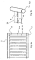
- Fig. 3b a perspective view of a detail of the channel and inlet.
- Fig. 1 shows a solar element according to the invention with solar cell carrier 1, frame 2 and tempering device 3 in cross section.
- the solar element is layered, consisting of a near-sun glass layer 13, an EVA layer 14 (ethylene vinyl acetate), the actual solar cell layer 15, another EVA layer 14 and then a subsequent layer of a plastic composite film of polyvinyl fluoride and polyester (Tedlar Mrs) 16th
- the frame 2 surrounds the edges of the solar cell carrier 1, which rests with its rear side on a support surface 17 of the frame 2.
- the support surface 17 is formed by a deep-drawn plate 19 made of ABS (acrylonitrile-butadiene-styrene copolymer), in the surface parallel to each other semi-cylindrical channels 5 are introduced.
- ABS acrylonitrile-butadiene-styrene copolymer
- channels 5 are completed by the solar cell carrier 1, so that in the ready-to-install solar element according to the invention from the channels 5 cavities 4 result, which are interconnected.
- This connection will have an in Fig. 1 not shown tubular inlet 7 for temperature control, here water, and a likewise not shown tubular outlet 8 made for temperature control.
- water is used as the temperature control agent.
- the invention advantageously also allows the generation of warm water, since the water used for the temperature control is heated as it passes through the solar elements according to the invention. In summer, so larger amounts of environmentally friendly heated water available, which can also be used as process water.
- Water can be promoted by means of a simple pump from the house supply lines through the solar elements according to the invention, there are no expensive and possibly polluting coolant required.
- contact devices 12 are provided for the temperature control, which are arranged laterally, that is orthogonal to the channels 5. These contact devices 12 are formed, for example, in the manner of sewer pipes, ie with conical areas which can be inserted into one another. Both inlet and outlet 7, 8 can be designed sealed.
- Solar elements according to the invention can be so easily and tightly plugged into each other and connect to a larger solar energy system. The result is a series of solar elements, the first solar element is connected to a water pipe, a cistern or a well and their inlet 7 and outlet 8 are each connected to the next solar element of the series.
- the unneeded openings of the contact devices of the first and last solar element are reversibly sealed with lids.
- the inlets 7 are below, so that incoming water first fills the inlets 7 of all solar elements of the series, then flows through the parallel channels 5 in approximately the same extent up to the installation position at the top arranged flows 8 and heated from there via the last solar element in the solar element series in the summer and cooled in winter escapes and is fed, for example, in a service water system.
- Inlet 7 and outlet 8 are dimensioned so that their inner volume corresponds approximately to that of the sum of all channels 5.
- the plate 19 further comprises support webs 18, on which the solar element carrier 1 rests. These support webs 18 have a width of about 5 mm.
- a reinforcement 10 may be provided in the form of steel rods, which increases the mechanical stability of the solar element according to the invention and the channel walls.
- a contact device 11 is provided for the electrical lines. According to the invention, all lines of the individual solar cells of the solar element are brought together in this contact device.
- This contact device is designed as a male / female connector, or in any other, known in the art manner adjacent to the contact devices for temperature control 12 or integrated into this.
- These contact devices 11, 12 allow a fast and secure connection of several inventive solar elements with as few tools. The solar system size achieved in this way can be adapted to any desired requirement.
- the solar element according to the invention is integrally formed after manufacture, solar cell carrier 1 and tempering 3 are connected by an injection-molded frame 2 made of plastic undetachably.
- ABS is considered as a plastic whose mechanical properties are particularly well suited to the requirements.
- any other plastic which has the required mechanical properties.
- a plate 19 carrying the channels 5 is first prepared in a suitable manner in the desired shape and size, for example by deep-drawing a plastic.
- a reinforcement 10th placed in an injection mold, followed by the plate 19 and an assembled from known components, non-laminated or laminated solar cell carrier 1.
- the tool is closed and injected the desired plastic, wherein the edges of the solar cell support 1, the reinforcement 10 and the plate 19 are sprayed with a certain thickness of material, as in Fig. 1 shown. If statically possible, not the entire plate 19 is encapsulated, but only the area between two channels with there inserted reinforcement 10 and the lateral, the solar cell carrier 1 encompassing area. In this case, a part of the plate 19 of a finished solar element would be visible.
- Fig.2 shows a partially sectioned sketch of three solar elements according to the invention mounted in mounting position on a roof 21 via mounting rails 20.
- Sketchy indicated the Temperierstoff für styvalutica 12 and the Temperierffenstrom in the channels 5.
- the inlet of the water takes place for all three solar elements in the lower area. Due to existing in the house water line or generated by a pump pressure, the water in the channels 5 rises up to a common all channels, continuous flow channel 8 and from there into a drain or hot water tank, not shown.
- the homogeneous temperature field generated below the solar cells improves their efficiency.
- the electrical connections are not shown, they are immediately adjacent to the Temperierstoff für 12 to make the design effort and nesting of the compounds when creating a solar element row as simple as possible.
- Fig. 3a shows a sketch-like view of the channel system 5 of a solar element with inlet and outlet (7, 8) without Temperierffenan say 12.
- the supervision lies in the plane directly below the Solar cell carrier 1.
- Between the semi-cylindrical channels 5 are support webs 18, and if necessary, below these arranged reinforcements 10.
- Inlet 7 and outlet 8 can be connected to adjacent solar elements.
- Fig. 3b shows a detail of the connection of inlet 7 and channel 5.
- the inlet 7 is formed as laterally open at intervals pipe, the channels 5 are formed in a plate 19 as approximately halved tubes, the longitudinal opening upwards to a solar cell carrier, not shown 1 point.
- the volume of the tube 7, 8 corresponds approximately to that of the sum of all channels 5 of a plate 19th
Landscapes
- Engineering & Computer Science (AREA)
- Physics & Mathematics (AREA)
- Life Sciences & Earth Sciences (AREA)
- Sustainable Development (AREA)
- Sustainable Energy (AREA)
- Thermal Sciences (AREA)
- Chemical & Material Sciences (AREA)
- Combustion & Propulsion (AREA)
- Mechanical Engineering (AREA)
- General Engineering & Computer Science (AREA)
- Photovoltaic Devices (AREA)
- Roof Covering Using Slabs Or Stiff Sheets (AREA)
Description
- Die vorliegende Erfindung betrifft ein Solarelement bestehend aus Solarzellenträger, Rahmen und Temperiereinrichtung, wobei der Rahmen wenigstens eine sonnenabgewandte Seite des Solarelements überdeckend ausgebildet ist und wobei die Temperiereinrichtung mehrere, miteinander verbundene Hohlräume aufweist, wobei die Hohlräume als voneinander beabstandete, miteinander verbundene Kanäle ausgebildet sind, die mit ihrer offenen Seite an den Solarzellenträger grenzend ausgebildet sind, sowie ein Verfahren zur Herstellung des Solarelements, und dessen Verwendung.
- Solarelemente bestehen üblicherweise aus einem rahmengefaßten Solarzellenträger, wobei letzterer in der Regellagenförmig aufgebaut ist. Dem Sonnenlicht zugewandt befindet sich eine Glasschicht, in der Regel Einscheiben-Sicherheitsglas, gefolgt von einer transparente Kunststoffschicht aus Ethylen-Vinylacetat (EVA), in die die eigentlichen Solarzellen, beispielsweise Photovoltaikzellen, eingebettet sind. Die mono- oder polykristallinen Solarzellen sind hierbei durch Lötbändchen elektrisch miteinander verschaltet. An die EVA-Schicht schließt sich eine Rückseitenkaschierung aus einer witterungsfesten Kunststoffverbundfolie an, die in der Regel aus Polyester und Polyvinylfluorid besteht, beispielsweise eine Tedlar-Folie. Solche Solarzellenträger werden mit der optisch aktiven Seite nach unten gefertigt. Auf ein Glas wird eine zugeschnittene EVA-Folie gelegt, darauf kommen die Solarzellen, die mittels Lötbändchen zu einzelnen Strängen verbunden und diese danach weiter elektrisch verkabelt werden. Eine weitere zugeschnittene EVA-Folie sowie die Tedlar-Folie schließen die Schichtung ab. Es folgt die Laminierung des so vorbereiteten Moduls bei Unterdruck und etwa 150°C, bei dem eine Polymerisationsreaktion in der EVA-Folie zu einem dreidimensional vernetzten, klaren und fest mit der Tedlarfolie und dem Glas verbundenen Kunststoff führt, der die Solarzellen umschließt. Abschließend wird der Solarzellenträger mittels eines Aluminiumrahmens gerahmt. Dieser Rahmen bedeckt nur die Kanten des Solarzellenträgers und lässt dessen Boden- und Sonnenseite zum allergrößten Teil frei. Das so vorbereitete Solarelement wird verpackt, verschickt und beispielsweise auf einem Hausdach zusammen mit weiteren Solarelementen montiert.
- Solche Solarelemente sind bruchgefährdet, insbesondere in Gebieten mit einer hohen winterlichen Schneelast, die bis zu 700 kg/m2 betragen kann. Die auf Hausdächem montierten Solarelemente sind in der Regel auf zwei, mehrere Solarelemente miteinander verbindenden Montageschienen angeordnet, wobei letztere mittels dachpfannenumgreifender Dachhaken an der Tragkonstruktion des Daches befestigt sind. Aufgrund dieser Anordnung biegen sich die Solarelemente bei höherer Schneelast leicht durch und können brechen. Bei dem Versuch, die Schneelast der auf Dächern montierten Solarelemente durch Abfegen zu verringern, kommt es immer wieder zu tödlich endenden Abstürzen.
- Dadurch, dass der Aluminiumrahmen die sonnenabgewandte Seite des Solarzellenträgers zum allergrößten Teil unbedeckt lässt, wird zwar dessen mechanische Stabilität nicht wesentlich erhöht, jedoch mit Vorteil dessen Hinterlüftung ermöglicht. Diese verbessert den stark temperaturabhängigen Wirkungsgrad der Solarzellen, da Luft an die im Sonnenlicht erhitzten Solarelemente herantreten und Wärme abführen kann. Bei hohen Außentemperaturen ist die Kühlwirkung einer solchen Hinterlüftung jedoch entsprechend gering und die Solarzellen weisen dann Betriebstemperaturen von etwa 70°C mit einer um etwa 20% gegenüber den Herstellerangaben reduzierten Leistungsfähigkeit auf.
-
JP 2000 11 4574 DE 298 10 238 U1 schlagen daher vor, auf der sonnenabgewandten Seite des Solargellenträgers Kühlkörper vorgesehen. - Die
DE 103 22 048 A1 offenbart eine Vorrichtung zur Gewinnung von thermischer und elektrischer Energie aus Sonnenenergie, deren Rahmen einen Solarzellenträger umgreift, wobei der Rahmen Kanäle für Kühlmittel aufweist, die mit ihrer offenen Seite an ein Solarmodul grenzen. - Nachteilig an dieser Erfindung ist, dass sie umständlich herzustellen und größeren Schneelasten nicht gewachsen ist.
- Es ist daher Aufgabe der Erfindung, ein bei hoher mechanischer Stabilität und Temperierleistung einfach herzustellendes und aufgebautes Solarelement, ein Herstellverfahren hierfür sowie dessen Verwendung anzugeben.
- Die gegenständliche Aufgabe wird dadurch gelöst, dass die Kanäle aus wenigstens einem Formteil, insbesondere Kunststoffformteil, gebildet sind und wobei der Rahmen Armierungen aufweist, vorzugsweise stabförmige Armierungen, die in überwiegend paralleler Richtung zu den Kanälen zwischen diesen angeordnet sind und wobei Solarzellenträger, Rahmen und Temperiereinrichtung einstückig ausgebildet sind. Dadurch, dass der Rahmen eine sonnenabgewandte Seite des Solarelements überdeckt, wird mit Vorteil eine hohe mechanische Stabilität erreicht. Die auf diese Weise gebildete mechanische Unterstützung führt dazu, daß auftretende Belastungen, beispielsweise in Form von hohen Schneelasten, nicht mehr zu Brüchen der Solarelemente führen, da diese vom Rahmen flächig gestützt werden. Ist die Temperiereinrichtung ein integraler Bestandteil des Rahmens, und sind Solarzellenträger, Rahmen und Temperiereinrichtung einstückig ausgebildet, ergibt sich eine einfache Handhabung des erfindungsgemäßen Solarelements. Das Vorsehen einer Temperiereinrichtung als untrennbarer und integraler Bestandteil des Rahmens vereinfacht Aufbau und Herstellung der erfindungsgemäßen Solarelemente deutlich. Der Rahmen schützt die integrierte Temperiereinrichtung vor Umwelteinflüssen oder Vandalismus und erlaubt die Verwendung handelsüblicher, fertig laminierter Solarzellenträger ohne weitere Modifikationen. Sind die Kanäle aus wenigstens einem Formteil, insbesondere Kunststoffformteil, gebildet, ergibt sich der Vorteil der einfachen Herstell- und Weiterverarbeitbarkeit des Formteils, insbesondere als Kunststoffformteil auch der des geringen Gewichts, der hohen Verschleißfestigkeit und langen Standzeit. Das Formteil mit den Kanälen kann aus demselben Material wie der Rahmen oder einem anderen gefertigt sein. Die Kanalstruktur ist einfach und kostengünstig über Tiefziehen eines in der Größe an ein gewünschten Solarzellenträger angepasstes rechteckiges Formteil aus beispielsweise Kunststoff herstellbar. Weist der Rahmen Armierungen auf, vorzugsweise stabförmige Stahlarmierungen, wobei die Armierungen in überwiegend paralleler Richtung zu den Kanälen zwischen diesen angeordnet sind, so ist vorteilhafterweise eine mechanische Verstärkung eines erfindungsgemäßen Solarelements verwirklicht. Die Anordnung der Armierungen zwischen den Kanälen verstärkt deren Wandung ohne weiteren Platzbedarf. Hierdurch kann Material beim Rahmen eingespart und das erfindungsgemäße Solarelement geringer dimensioniert werden.
- In Ausgestaltung der Erfindung ist vorgesehen, dass die Kanäle überwiegend parallel ausgebildet sind, und an ihren Stirnseiten über einen gemeinsamen Zulauf und einen gemeinsamen Ablauf miteinander verbunden ausgebildet sind. Diese Ausgestaltung erlaubt mit großem Vorteil eine effektive Temperierung der Solarzellen. Die Kanäle verlaufen erfindungsgemäß jeweils unterhalb einer Reihe der im Solarzellenträger reihenförmig angeordneten Solarzellen. Da erfindungsgemäß der Sölarzellenträger direkt an die Kanäle grenzt, ist der Wärmeübergang von den Solarzellen in das Temperiermittel leicht und effizient. Bei Belastung durch Schnee läßt sich das Temperiermittel auch zum Erwärmen der Solarelemente einsetzen, so daß der auf dem Solarelement aufliegende Schnee abschmilzt, beziehungsweise auf einer geschmolzene Schneeschicht vom Solarelement herabgleitet. Auf diese Weise ist das gefährliche winterliche Abfegen der Solarelemente nicht länger nötig. Der gemeinsame Temperiermittelzulauf und -ablauf der Kanäle trägt ebenfalls zu einer effektiven Temperierung bei. Das Temperiermittel strömt dabei von dem in der üblichen geneigten Einbaulage der Solarelemente unten befindlichen Zulauf gleichzeitig durch alle parallelen Kanäle eines Solarelements zu dem in der geneigten Einbaulage oben befindlichen Ablauf, so dass sich ein homogenes Temperaturfeld erreichen lässt, das alle Solarzellen in gleichem Maße temperiert. Grundsätzlich ist auch ein einzelner, mäandrierender Hohlraum denkbar. Durch die Beabstandung der Kanäle voneinander ist die Anordnung einer Armierung zwischen diesen möglich, falls es aus statischen Gründen erforderlich ist, ohne die Bauhöhe des erfindungsgemäßen Solarelements unnötig zu vergrößern.
- Schließlich ist erfindungsgemäß auch vorgesehen, dass der Rahmen wenigstens je eine, insbesondere jeweils gedichtete seitliche, Kontaktvorrichtung für eine elektrische und eine Temperiermittelverbindung zu einem weiteren Solarelement aufweist, wobei die elektrische Kontaktvorrichtung einen Kontakt zu sämtlichen Solarzellen eines Solarelements herstellend ausgebildet ist. Auf diese Weise lassen sich mehrere Rahmen einfach miteinander zu einem größeren System mit einem durchgehenden Temperiersystem verbinden, wobei das Temperiermittel durch das gesamte Solarelementsystem geführt wird. Es entfällt mit Vorteil die Notwendigkeit, zusätzliche Verdrahtungen zwischen einzelnen Rahmen vorzusehen. Es ist vielmehr möglich, alle Leitungen der Zellen eines Solarelements an der elektrischen Kontaktvorrichtung eines Rahmens zu bündeln und diesen an nur dieser einen Stelle mittels der elektrischen Kontaktvorrichtung an einen zweiten Rahmen anzuschließen. Auf diese Weise lassen sich die erfindungsgemäßen Rahmen ohne Werkzeug einfach zu einem größeren System verbinden. Wenn die Kontaktvorrichtungen gedichtet ausgebildet sind, ist sowohl ein Temperiermittelvedust ausgeschlossen, als auch ein schädigender Umwelteinfluß auf die elektrischen Leitungen, beispielsweise durch Feuchtigkeit.
- Besteht der Rahmen aus Kunststoff, vorzugsweise aus einem verstärkten Kunststoff, insbesondere aus einem faserverstärktem oder armiertem Kunststoff, ganz insbesondere aus einem Polyurethan oder einem Acrylnitril-Butadien-Styrol-Copolymerisat, werden folgende Vorteile realisiert: Ein solcher Rahmen ist bei gleicher mechanischer Stabilität leichter als ein Metallrahmen. Für besonders schneelastgefährdete Einsatzorte ist erfindungsgemäß eine Faserverstärkung oder eine Armierung vorgesehen, so daß Lasten von bis zu 500 kg/m2 Solarelementfläche bewältigt werden können. Der Kunststoffrahmen läßt sich über Herstellverfahren herstellen, die geringere Kosten als die metallener Rahmen verursachen, so daß geringere Gestehungskosten anfallen. Ein solcher Rahmen ist beispielsweise über Spritzgießverfahren herstellbar.
- Die Verfahrensaufgabe der Erfindung wird dadurch gelöst, dass ein Herstellverfahren die Schritte umfasst:
- Einlegen eines Formteils sowie gegebenenfalls wenigstens einer Armierung in ein Spritzgießwerkzeug,
- Einlegen eines Solarzellenträgers, so dass der Solarzellenträger wenigstens teilweise auf dem Formteil aufliegt und
- Spritzgießen eines gemeinsamen Rahmens um das Formteil, die gegebenenfalls wenigstens eine Armierung und den Solarzellenträger.
- Zur Erfindung gehört ebenfalls ein Bausatz für eine Solarenergieanlage, bestehend aus mindestens zwei Solarelementen gemäß der oben geschilderten Merkmale, Montageschienen und Dachhaken. Ein solcher Bausatz erlaubt mit großem Vorteil eine schnelle, kostengünstige Montage eines effizienten Solarenergiesystems.
- Zur Erfindung gehört ebenfalls die Verwendung eines Solarelements wie geschildert für eine Solarenergieanlage.
- Schließlich gehört noch eine Solarenergieanlage zur Erfindung, die mindestens zwei Solarelemente wie geschildert umfasst, vorzugsweise jedoch bis zu 15.
- Die Erfindung wird im Weiteren anhand der Figur einer Zeichnung erläutert, wobei
- Fig. 1
- einen Schnitt durch einen erfindungsgemäßen Rahmen darstellt,
- Fig. 2
- eine Skizze von drei zusammengesteckten Solarelementen in Einbaulage,
- Fig. 3a
- eine geschnittene Aufsicht auf die miteinander verbundenen Kanäle und
-
Fig. 3b eine perspektivische Ansicht eines Detail von Kanal und Zulauf. -
Fig. 1 zeigt ein erfindungsgemäßes Solarelement mit Solarzellenträger 1, Rahmen 2 und Temperiereinrichtung 3 im Querschnitt. Das Solarelement ist geschichtet aufgebaut, bestehend aus einer sonnennahen Glasschicht 13, einer EVA-Schicht 14 (Ethylenvinylacetat), der eigentlichen Solarzellenschicht 15, einer weiteren EVA-Schicht 14 sowie daran anschließend einer Schicht aus einer Kunststoffverbundfolie aus Polyvinylfluorid und Polyester (Tedlarschicht) 16. Der Rahmen 2 umgreift die Kanten des Solarzellenträgers 1, der mit seiner Rückseite auf einer Auflagefläche 17 des Rahmens 2 aufliegt. Die Auflagefläche 17 wird dabei durch eine tiefgezogene Platte 19 aus ABS (Acrylnitril-Butadien-Styrol-Copolymerisat) gebildet, in deren Oberfläche zueinander parallele halbzylindrische Kanäle 5 eingebracht sind. Diese Kanäle 5 werden durch den Solarzellenträger 1 abgeschlossen, so dass sich im einbaufertigen erfindungsgemäßen Solarelement aus den Kanälen 5 Hohlräume 4 ergeben, die miteinander verbunden sind. Diese Verbindung wird über einen inFig. 1 nicht dargestellten rohrförmigen Zulauf 7 für Temperiermittel, hier Wasser, und einen ebenfalls nicht dargestellten rohrförmigen Ablauf 8 für Temperiermittel hergestellt. Erfindungsgemäß ist vorgesehen, dass vor allem Wasser ais Temperiermittel verwendet wird. Hierdurch erlaubt die Erfindung mit Vorteil auch die Erzeugung von warmem Wasser, da sich das zur Temperierung eingesetzte Wasser beim Durchlauf durch die erfindungsgemäßen Solarelemente erwärmt. Im Sommer stehen so größere Mengen umweltfreundlich erwärmten Wassers zur Verfügung, das auch als Brauchwasser verwendet werden kann. Wasser kann mittels einer einfachen Pumpe aus den Hausversorgungsleitungen durch die erfindungsgemäßen Solarelemente gefördert werden, es sind keine teuren und eventuell umweltschädlichen Kühlmittel erforderlich. Im Rahmen 2 sind Kontaktvorrichtungen 12 für das Temperiermittel vorgesehen, die seitlich, also orthogonal zu den Kanälen 5 angeordnet sind. Diese Kontaktvorrichtungen 12 sind beispielsweise nach Art von Kanalrohren ausgebildet, also mit ineinander steckbaren konischen Bereichen. Sowohl Zu- als auch Ablauf 7, 8 können gedichtet ausgebildet sein. Erfindungsgemäße Solarelemente lassen sich so leicht und dicht ineinander stecken und zu einer größeren Solarenergieanlage verbinden. Als Resultat ergibt sich eine Solarelementreihe, deren erstes Solarelement an eine Wasserleitung, eine Zisterne oder einen Brunnen angeschlossen ist und deren Zulauf 7 und Ablauf 8 jeweils mit dem nächsten Solarelement der Reihe verbunden sind. Die nichtbenötigten Öffnungen der Kontaktvorrichtungen des ersten und letzten Solarelements werden mit Deckeln reversibel dicht verschlossen. In Einbaulage der Solarelemente auf einem Dach befinden sich die Zuläufe 7 unten, so dass einlaufendes Wasser zunächst die Zuläufe 7 sämtlicher Solarelemente der Reihe füllt, anschließend durch die parallelen Kanäle 5 in etwa gleichem Maße nach oben zu den in Einbaulage oben angeordneten Abläufen 8 strömt und von dort über das letzte Solarelement in der Solarelementreihe im Sommer erwärmt und im Winter abgekühlt austritt und beispielsweise in ein Brauchwassersystem eingespeist wird. Zulauf 7 und Ablauf 8 sind dabei so dimensioniert, dass ihr Innenvolumen jeweils in etwa demjenigen der Summe aus sämtlichen Kanälen 5 entspricht. Zu einem bestimmten Zeitpunkt befindet sich daher etwa genauso viel Wasser im Zulauf 7, wie in den Kanälen 5 eines Solarelements, bzw. einer Solarelementreihe. Das in den Kanälen 5 strömende Wasser steht in Kontakt mit dem Solarzellenträger 1, da dieser eine Wand der Kanäle 5 bildet. Zwischen den Kanälen 5, die hier halbzylindrisch ausgebildet sind, jedoch auch jede andere geeignete Form annehmen können, weist die Platte 19 weiterhin Auflagestege 18 auf, auf denen der Solarelementträger 1 aufliegt. Diese Auflagestege 18 haben eine Breite von etwa 5 mm. Zwischen zwei Kanälen 5 ist, falls erforderlich, eine Armierung 10 in Form von Stahlstäben vorgesehen sein, die die mechanische Stabilität des erfindungsgemäßen Solarelements und der Kanalwandungen erhöht. - Neben den Kontaktvorrichtungen für Temperiermittel 12 ist eine Kontaktvorrichtung 11 für die elektrischen Leitungen vorgesehen. Erfindungsgemäß sind in dieser Kontaktvorrichtung alle Leitungen der einzelnen Solarzellen des Solarelements zusammengeführt. Diese Kontaktvorrichtung ist als männlicher/weiblicher Stecker ausgeführt, oder in jeder anderen, dem Fachmann bekannten Art und Weise benachbart zu den Kontaktvorrichtungen für Temperiermitteln 12 oder in diese integriert. Diese Kontaktvorrichtungen 11, 12 erlauben ein schnelles und sicheres Verbinden mehrerer erfindungsgemäßer Solarelemente mit möglichst wenigen Werkzeugen. Die so erzielte Solaranlagengröße kann jeder gewünschten Anforderung angepaßt werden.
- Das erfindungsgemäße Solarelement ist nach Fertigung einstückig ausgebildet, Solarzellenträger 1 und Temperiereinrichtung 3 sind durch einen spritzgegossenen Rahmen 2 aus Kunststoff unlösbar miteinander verbunden. Als Kunststoff kommt hierbei insbesondere ABS in Betracht, dessen mechanische Eigenschaften den Anforderungen besonders gut entsprechen Es ist jedoch auch jeder andere Kunststoff verwendbar, der die erforderlichen mechanischen Eigenschaften aufweist. Zur Herstellung des erfindungsgemäßen Solarelements wird zunächst eine die Kanäle 5 tragende Platte 19 in geeigneter Weise in gewünschter Form und Größe hergestellt, beispielsweise durch Tiefziehen eines Kunststoffs. Für die Herstellung des Solarelements wird, falls erforderlich, eine Armierung 10 in ein Spritzgießwerkzeug eingelegt, gefolgt von der Platte 19 sowie einem aus bekannten Bauteilen zusammengesetztem, nicht laminiertem oder laminiertem Solarzellenträger 1. Im nächsten Schritt wird das Werkzeug geschlossen und der gewünschte Kunststoff eingespritzt, wobei die Kanten des Solarzellenträgers 1, die Armierung 10 und die Platte 19 mit einer gewissen Materialstärke umspritzt werden, so wie in
Fig. 1 dargestellt. Falls statisch möglich, wird nicht die gesamte Platte 19 umspritzt, sondern nur der Bereich zwischen zwei Kanälen mit dort eingelegter Armierung 10 und der seitliche, den Solarzellenträger 1 umgreifende Bereich. In diesem Fall wäre ein Teil der Platte 19 eines fertigen Solarelements sichtbar. -
Fig.2 zeigt eine teilweise geschnittene Skizze von drei erfindungsgemäßen Solarelementen in Einbaulage auf einem Dach 21 befestigt über Montageschienen 20. Skizzenhaft angedeutet sind die Temperiermittelverbindungen 12 sowie der Temperiermittelstrom in den Kanälen 5. Der Zulauf des Wassers erfolgt für alle drei Solarelemente im unteren Bereich. Aufgrund des in der Hauswasserleitung vorhandenen oder durch eine Pumpe erzeugten Drucks steigt das Wasser in den Kanälen 5 nach oben zu einem allen Kanälen gemeinsamen, durchgehenden Ablaufkanal 8 und von dort in einen nicht dargestellten Ablauf oder Brauchwassertank. Das so unterhalb der Solarzellen erzeugte, homogene Temperaturfeld verbessert deren Effizienz. Die elektrischen Verbindungen sind nicht dargestellt, sie befinden sich unmittelbar benachbart zu den Temperiermittelverbindungen 12, um den konstruktiven Aufwand und das Ineinanderstecken der Verbindungen beim Erstellen einer Solarelementreihe möglichst einfach zu gestalten. -
Fig. 3a zeigt eine skizzenhafte Aufsicht auf das Kanalsystem 5 eines Solarelements mit Zu- und Ablauf (7, 8) ohne Temperiermittelanschlüsse 12. Die Aufsicht liegt dabei in der Ebene direkt unterhalb des Solarzellenträgers 1. Zwischen den halbzylindrischen Kanälen 5 befinden sich Auflagestege 18, und gebenenfalls darunter angeordnete Armierungen 10. Zulauf 7 und Ablauf 8 können mit benachbarten Solarelementen verbunden werden. -
Fig. 3b zeigt ein Detail aus der Verbindung von Zulauf 7 und Kanal 5. Der Zulauf 7 ist als seitlich in Abständen geöffnetes Rohr ausgebildet, wobei die Kanäle 5 in einer Platte 19 als etwa halbierte Rohre ausgebildet sind, deren Längsöffnung nach oben, zu einem nicht dargestellten Solarzellenträger 1 weisen. Das Volumen des Rohres 7, 8 entspricht in etwa demjenigen der Summe aller Kanäle 5 einer Platte 19. -
- 1.
- Solarzellenträger
- 2.
- Rahmen
- 3.
- Temperiereinrichtung
- 4.
- Hohlraum
- 5.
- Kanal
- 6.
- Stirnseite
- 7.
- Zulauf
- 8.
- Ablauf
- 9.
- Formteil
- 10.
- Armierung
- 11.
- elektrische Verbindung
- 12.
- Temperiermittelverbindung
- 13.
- Glasschicht
- 14.
- EVA-Schicht
- 15.
- Tedlar-Schicht
- 16.
- Solarzellen
- 17.
- Auflagefläche
- 18.
- Auflagestege
- 19.
- Platte
- 20.
- Montageschiene
- 21.
- Dach
Claims (8)
- Solarelement bestehend aus Solarzellenträger (1), Rahmen (2) und Temperiereinrichtung (3), wobei der Rahmen (2) wenigstens eine sonnenabgewandte Seite des Solarelements überdeckend ausgebildet ist und wobei die Temperlerelnrichtung (3) integraler Bestandteil des Rahmens (2) ist, und wobei die Temperiereinrichtung (3) mehrere, miteinander verbundene Hohlräume (4) aufweist, wobei die Hohlräume (4) als voneinander beabstandete, miteinander verbundene Kanäle (5) ausgebildet sind und die mit ihrer offenen Seite an den Solarzellenträger (1) grenzend ausgebildet sind, dadurch gekennzeichnet, dass die Kanäle (5) überwiegend parallel ausgebildet sind und an ihren Stirnseiten (6) über einen Zulauf (7) und einen Ablauf (8) miteinander verbunden ausgebildet sind und dass die Kanäle (5) aus wenigstens einem Formteil (9), insbesondere Kunststoffformteil, gebildet sind und wobei der Rahmen (2) Armierungen (10) aufweist, vorzugsweise stabförmige Stahlarmierungen, die in überwiegend paralleler Richtung zu den Kanälen (5) zwischen diesen angeordnet sind und wobei Solarzellenträger (1), Rahmen (2) und Temperiereinrichtung (3) einstückig ausgebildet sind.
- Solarelement gemäß Anspruch 1 dadurch gekennzeichnet, dass der Rahmen (2) wenigstens je eine, insbesondere jeweils gedichtete seitliche, Kontaktvorrichtung für eine elektrische (11) und eine Temperlermittelverbindung (12) zu einem weiteren Solarelement aufweist, wobei die elektrische Kontaktvorrichtung (11) einen Kontakt zu sämtlichen Solarzellen eines Solarelements herstellend ausgebildet ist.
- Solarelement gemäß Anspruch 1 oder 2, dadurch gekennzeichnet, dass der Rahmen (2) aus Kunststoff besteht, vorzugsweise aus einem verstärkten Kunststoff, insbesondere aus einem faserverstärktem oder armiertem Kunststoff, ganz insbesondere aus einem Polyurethan oder einem Acrylnitril-Butadien-Styrol-Copolymerisat.
- Solarelement gemäß einem der vorherigen Ansprüche, dadurch gekennzeichnet, dass der Rahmen (2) mittels Spritzgießens herstellbar ist.
- Verfahren zur Herstellung eines Solarelemente nach Anspruch 1, mit den Schritten:a) Einlegen eines Formteils (9) sowie gegebenenfalls wenigstens einer Armierung (10) in ein Spritzgießwerkzeug,b) Einlegen eines Solarzellenträgers, so dass der Solarzellenträger wenigstens teilweise auf dem Formteil (9) aufliegt undc) Spritzgießen eines gemeinsamen Rahmens (2) um das Formteil (9), die gegebenenfalls wenigstens eine Armierung (10) und den Solarzellenträger (1).
- Bausatz für eine Solarenergieanlage, bestehend aus mindestens zwei Solarelementen gemäß einem der Ansprüche 1 bis 4, Montageschienen und Dachhaken.
- Verwendung eines Solarelements gemäß einem der Ansprüche 1 bis 4 für eine Solarenergieanlage.
- Solarenergieanlage, umfassend mindestens zwei Solarelemente gemäß einem der Ansprüche 1 bis 4, vorzugsweise 15 Solarelemente.
Applications Claiming Priority (2)
| Application Number | Priority Date | Filing Date | Title |
|---|---|---|---|
| DE102006027629A DE102006027629B4 (de) | 2006-06-13 | 2006-06-13 | Solarelement mit Temperiereinrichtung, Verfahren zur Herstellung, Bausatz, Verwendung für eine Solarenergieanlage sowie Solarenergieanlage |
| PCT/EP2007/005063 WO2007144113A1 (de) | 2006-06-13 | 2007-06-08 | Solarelement mit temperiereinrichtung |
Publications (2)
| Publication Number | Publication Date |
|---|---|
| EP2033231A1 EP2033231A1 (de) | 2009-03-11 |
| EP2033231B1 true EP2033231B1 (de) | 2012-10-24 |
Family
ID=38477263
Family Applications (1)
| Application Number | Title | Priority Date | Filing Date |
|---|---|---|---|
| EP07725908A Not-in-force EP2033231B1 (de) | 2006-06-13 | 2007-06-08 | Solarelement mit Temperiereinrichtung |
Country Status (6)
| Country | Link |
|---|---|
| US (1) | US8307819B2 (de) |
| EP (1) | EP2033231B1 (de) |
| CN (1) | CN101501868B (de) |
| CA (1) | CA2671919C (de) |
| DE (1) | DE102006027629B4 (de) |
| WO (1) | WO2007144113A1 (de) |
Families Citing this family (23)
| Publication number | Priority date | Publication date | Assignee | Title |
|---|---|---|---|---|
| DE102008035054A1 (de) * | 2008-07-26 | 2010-01-28 | Robert Bosch Gmbh | Solarkollektor und dessen Herstellungsverfahren |
| US20120110932A1 (en) * | 2009-06-06 | 2012-05-10 | Bayer Materialscience Ag | Pan tile/roofing tile/facade element with integrated solar module |
| GB2471844A (en) * | 2009-07-13 | 2011-01-19 | Nissim Leon Jacob | Composite solar collector |
| EP2284910B1 (de) * | 2009-08-12 | 2016-03-02 | Roth Werke GmbH | Solarabsorber |
| DE102010012002A1 (de) * | 2010-03-15 | 2011-09-15 | Dr. Doll Holding Gmbh | Aufnahmebehältnis und Verfahren zu seiner Herstellung |
| DE202011004351U1 (de) | 2010-09-13 | 2011-12-14 | Meindl-Köhle Umform- und Systemtechnik GmbH & Co. KG | Von einem Wärmeträger durchströmtes Trägermodul, insbesondere Trägermodul für Photovoltaikzellen; Vorrichtung zur Herstellung eines derartigen Trägermoduls |
| DE102010050249B4 (de) | 2010-09-13 | 2013-03-07 | Meindl-Köhle Umform- und Systemtechnik GmbH & Co. KG | Von einem Wärmeträger durchströmtes Trägermodul, insbesondere Trägermodul für Photovoltaikzellen;Verfahren und Vorrichtung zur Herstellung eines derartigen Trägermoduls |
| US20120145306A1 (en) * | 2010-12-09 | 2012-06-14 | Certainteed Corporation | Process of forming a member for a structure including a solar control layer |
| DE202011110227U1 (de) | 2011-05-26 | 2013-02-15 | Willi Bihler | Kombinierte Photovoltaik- und Solarthermieanlage |
| FR2978299B1 (fr) | 2011-07-19 | 2014-05-09 | Solaire 2G | Amelioration de la longevite et de l’ergonomie des modules solaires hybrides |
| CN102412328A (zh) * | 2011-10-13 | 2012-04-11 | 英利能源(中国)有限公司 | 一种封装太阳能电池的注塑底板和方法 |
| DE102011055311A1 (de) * | 2011-11-11 | 2013-05-16 | Bernd Schneider | Verfahren zur Herstellung von Wärmetauscherkörpern und Wärmetauscherkörper für plattenförmige Solarmodule |
| CN104205622A (zh) * | 2012-03-30 | 2014-12-10 | 法国圣戈班玻璃厂 | 具有冷却设备的光伏模块 |
| CN103580599B (zh) * | 2012-08-08 | 2016-03-30 | 江苏源盛复合材料技术股份有限公司 | 一种聚氨酯型材 |
| CN103094391B (zh) * | 2013-01-18 | 2016-06-08 | 常州亿晶光电科技有限公司 | 太阳能电池冷却组件及其边框 |
| DE202013008494U1 (de) | 2013-09-24 | 2013-11-21 | Institut für Solarenegerieforschung GmbH | Solarheizung mit photovolatisch-thermischen Kollektor |
| JP2016032312A (ja) * | 2014-07-28 | 2016-03-07 | 有限会社エヌテック | 太陽電池パネル |
| DE102016004853B4 (de) * | 2016-04-22 | 2019-09-12 | Josef Griesmayr | Photothermie - Modul |
| WO2018013066A1 (en) * | 2016-07-11 | 2018-01-18 | Shramko Serhii Ivanovych | Solar collector |
| US10490682B2 (en) | 2018-03-14 | 2019-11-26 | National Mechanical Group Corp. | Frame-less encapsulated photo-voltaic solar panel supporting solar cell modules encapsulated within multiple layers of optically-transparent epoxy-resin materials |
| CN113237130B (zh) * | 2021-03-30 | 2022-03-18 | 江苏四季沐歌有限公司 | 一种太阳能空气能高效循环采暖系统 |
| DE102022003363A1 (de) | 2022-09-13 | 2024-03-14 | Pitt Fischer | Balkon'' - Nah-Heizwerk im Modulgerätesystem, zur kostenlosen Erzeugung von Wärme durch Sonnenenergie. |
| DE202023000405U1 (de) | 2022-09-13 | 2023-04-04 | Pitt Fischer | Balkon - Nahheizwerk im Modulgerätesystem, zur kostenlosen Erzeugung von Wärme durch Sonnenenergie |
Family Cites Families (27)
| Publication number | Priority date | Publication date | Assignee | Title |
|---|---|---|---|---|
| US4112918A (en) * | 1977-03-02 | 1978-09-12 | Exxon Research & Engineering Co. | Solar energy collector |
| US4279243A (en) * | 1977-11-14 | 1981-07-21 | Deakin David A | Solar collector panel |
| DE3038671C2 (de) * | 1980-10-14 | 1984-04-26 | Licentia Patent-Verwaltungs-Gmbh, 6000 Frankfurt | Sonnenkollektor |
| DE3112468A1 (de) * | 1981-03-28 | 1982-10-07 | M.A.N. Maschinenfabrik Augsburg-Nürnberg AG, 8000 München | "sonnenenergiewandler mit gekuehlten solarzellen" |
| FR2506813A1 (fr) * | 1981-06-02 | 1982-12-03 | Bouygues Sa | Element de toiture |
| US4586227A (en) * | 1984-05-07 | 1986-05-06 | Cornell S Douglas | Method of making a solar water heater |
| DE3513910C2 (de) * | 1985-04-17 | 1994-08-25 | Siemens Ag | Solarmodul |
| US5008062A (en) * | 1988-01-20 | 1991-04-16 | Siemens Solar Industries, L.P. | Method of fabricating photovoltaic module |
| DE3831631A1 (de) * | 1988-09-17 | 1990-03-29 | Telefunken Systemtechnik | Solarzellen mit kuehlvorrichtung |
| DE4301404C1 (de) * | 1993-01-20 | 1994-07-28 | Michael C Lenz | Verfahren zur Herstellung von Solargeneratoren |
| WO1996008683A1 (en) * | 1994-09-15 | 1996-03-21 | Colin Francis Johnson | Solar concentrator for heat and electricity |
| US5628214A (en) * | 1995-01-06 | 1997-05-13 | Bolt Security Products, Inc. | Bicycle lock |
| US5743970A (en) * | 1995-12-13 | 1998-04-28 | Energy Conversion Devices, Inc. | Photovoltaic module having an injection molded encapsulant |
| US5986203A (en) * | 1996-06-27 | 1999-11-16 | Evergreen Solar, Inc. | Solar cell roof tile and method of forming same |
| US6052961A (en) * | 1996-07-30 | 2000-04-25 | Gibbs; Alden T. | Roof mounting assembly |
| DE19651226A1 (de) * | 1996-12-10 | 1998-06-18 | Peter Fabritz | Photo-Voltaic-Kollektor |
| JP3792867B2 (ja) * | 1997-11-06 | 2006-07-05 | キヤノン株式会社 | 太陽電池モジュール、太陽電池アレイ及び太陽光発電装置の施工方法 |
| DE29810238U1 (de) * | 1998-06-09 | 1999-10-21 | Autokühler GmbH & Co KG, 34369 Hofgeismar | Solarzellenanordnung |
| IT1303609B1 (it) * | 1998-06-10 | 2000-11-15 | Adriano Trimboli | Sistema dinamico termico-fotovoltaico. |
| JP2000114574A (ja) * | 1998-10-02 | 2000-04-21 | Ykk Architectural Products Inc | 太陽電池ユニットおよび太陽電池冷却システム |
| DK199900556A (da) * | 1999-04-23 | 2000-10-24 | Velux Ind As | Panelsystem |
| DE19958053A1 (de) * | 1999-12-02 | 2001-06-07 | Schultze Kraft Andreas | Stromerzeugende Formteile aus glasgefülltem und flachglasbeschichtetem Polymerkunststein mit integrierten Solarzellen |
| JP2003318432A (ja) * | 2002-04-22 | 2003-11-07 | Matsushita Electric Works Ltd | 太陽光発電集熱複合パネルとその製造方法 |
| DE10322048A1 (de) * | 2002-05-16 | 2003-11-27 | Manfred Jezerkowsky | Vorrichtung zur Gewinnung von thermischer und elektrischer Energie aus Sonnenenergie |
| JP3701639B2 (ja) * | 2002-08-29 | 2005-10-05 | 本田技研工業株式会社 | 電動機のリードフレーム及びこれを用いた配電部品 |
| DE20216297U1 (de) * | 2002-10-23 | 2003-01-09 | Rheinzink GmbH & Co. KG, 45711 Datteln | Heliothermischer Flachkollektor-Modul in Sandwichbauweise |
| TWM281155U (en) * | 2005-04-26 | 2005-11-21 | Guo-Yan Jeng | Heat exchanging sheet for roof and heat exchanging device |
-
2006
- 2006-06-13 DE DE102006027629A patent/DE102006027629B4/de not_active Expired - Fee Related
-
2007
- 2007-06-08 US US12/302,352 patent/US8307819B2/en not_active Expired - Fee Related
- 2007-06-08 EP EP07725908A patent/EP2033231B1/de not_active Not-in-force
- 2007-06-08 WO PCT/EP2007/005063 patent/WO2007144113A1/de not_active Ceased
- 2007-06-08 CA CA2671919A patent/CA2671919C/en not_active Expired - Fee Related
- 2007-06-08 CN CN2007800300945A patent/CN101501868B/zh not_active Expired - Fee Related
Also Published As
| Publication number | Publication date |
|---|---|
| DE102006027629B4 (de) | 2013-10-17 |
| CN101501868A (zh) | 2009-08-05 |
| US20090188489A1 (en) | 2009-07-30 |
| CA2671919A1 (en) | 2007-12-21 |
| EP2033231A1 (de) | 2009-03-11 |
| CA2671919C (en) | 2010-07-13 |
| US8307819B2 (en) | 2012-11-13 |
| WO2007144113A1 (de) | 2007-12-21 |
| CN101501868B (zh) | 2013-03-13 |
| DE102006027629A1 (de) | 2007-12-27 |
Similar Documents
| Publication | Publication Date | Title |
|---|---|---|
| EP2033231B1 (de) | Solarelement mit Temperiereinrichtung | |
| EP3295509B1 (de) | Energiespeicher eines kraftfahrzeugs | |
| DE102011054649B4 (de) | Deckelement für Dächer oder sonstige der Sonnenenergie ausgesetzte Flächengebilde sowie System zur Nutzung von Sonnenenergie | |
| EP0041724A1 (de) | Von einer Flüssigkeit durchströmte Platte | |
| DE102008049890A1 (de) | Photovoltaische Anordnung und Verfahren zur Herstellung der photovoltaischen Anordnung | |
| EP2710638A1 (de) | Solarmodul | |
| EP2190030A2 (de) | Photovoltaikeinheit, Photovoltaiksystem sowie Verfahren zur Herstellung einer Photovoltaikeinheit | |
| DE102011055311A1 (de) | Verfahren zur Herstellung von Wärmetauscherkörpern und Wärmetauscherkörper für plattenförmige Solarmodule | |
| EP3365973B1 (de) | Rückseitenelement für ein solarmodul | |
| AT503907A1 (de) | Solarmodul | |
| EP0496217A1 (de) | Absorberkörper mit Strömungswegen für Wasser oder einen strömbaren Wärmeträger sowie Verfahren zu dessen Herstellung | |
| DE102010037500A1 (de) | Solarer Hybridkollektor zur Erzeugung elektrischer und/oder thermischer Energie | |
| DE102010009478A1 (de) | Fahrzeug mit einem gekühlten elektrischen Speicher | |
| DE102008003286A1 (de) | Photovoltaikelement, Trägerstruktur und Verfahren zur Montage einer Trägerstruktur dazu | |
| EP2131120A2 (de) | Solarkollektor | |
| DE202010008521U1 (de) | Solarer Hybridkollektor zur Erzeugung elektrischer und/oder thermischer Energie | |
| DE202012013211U1 (de) | Thermoanordnung | |
| DE102013201582B4 (de) | Verfahren zur Herstellung einer Kühlvorrichtung für eine Batterieeinheit, Kühlvorrichtung für eine Batterieeinheit sowie Batterieeinheit | |
| EP2544246B1 (de) | Kombi-Solarmodul | |
| EP2458648B1 (de) | Hybrid-Kollektor | |
| EP2567410B1 (de) | Hybridkollektor | |
| WO2014202231A1 (de) | Solarmodul mit rückseitenverstärkung | |
| EP2685200B1 (de) | Konduktionstragkörper mit geschäumtem metallischen Kern und Verfahren zu dessen Herstellung | |
| EP2978126B1 (de) | Solarmodultemperieranordnung | |
| DE202025002094U1 (de) | PV-Modul und PVT-Kollektor mit Rahmen |
Legal Events
| Date | Code | Title | Description |
|---|---|---|---|
| PUAI | Public reference made under article 153(3) epc to a published international application that has entered the european phase |
Free format text: ORIGINAL CODE: 0009012 |
|
| 17P | Request for examination filed |
Effective date: 20090113 |
|
| AK | Designated contracting states |
Kind code of ref document: A1 Designated state(s): AT BE BG CH CY CZ DE DK EE ES FI FR GB GR HU IE IS IT LI LT LU LV MC MT NL PL PT RO SE SI SK TR |
|
| AX | Request for extension of the european patent |
Extension state: AL BA HR MK RS |
|
| REG | Reference to a national code |
Ref country code: DE Ref legal event code: R079 Ref document number: 502007010755 Country of ref document: DE Free format text: PREVIOUS MAIN CLASS: H01L0031058000 Ipc: F24J0002200000 |
|
| DAX | Request for extension of the european patent (deleted) | ||
| RIC1 | Information provided on ipc code assigned before grant |
Ipc: H01L 31/048 20060101ALI20120719BHEP Ipc: F24J 2/20 20060101AFI20120719BHEP Ipc: H01L 31/052 20060101ALI20120719BHEP Ipc: H01L 31/058 20060101ALI20120719BHEP Ipc: F24J 2/46 20060101ALI20120719BHEP Ipc: H01L 31/042 20060101ALI20120719BHEP Ipc: F24J 2/24 20060101ALI20120719BHEP |
|
| GRAP | Despatch of communication of intention to grant a patent |
Free format text: ORIGINAL CODE: EPIDOSNIGR1 |
|
| GRAS | Grant fee paid |
Free format text: ORIGINAL CODE: EPIDOSNIGR3 |
|
| GRAA | (expected) grant |
Free format text: ORIGINAL CODE: 0009210 |
|
| AK | Designated contracting states |
Kind code of ref document: B1 Designated state(s): AT BE BG CH CY CZ DE DK EE ES FI FR GB GR HU IE IS IT LI LT LU LV MC MT NL PL PT RO SE SI SK TR |
|
| REG | Reference to a national code |
Ref country code: GB Ref legal event code: FG4D Free format text: NOT ENGLISH |
|
| REG | Reference to a national code |
Ref country code: CH Ref legal event code: EP |
|
| REG | Reference to a national code |
Ref country code: AT Ref legal event code: REF Ref document number: 581157 Country of ref document: AT Kind code of ref document: T Effective date: 20121115 |
|
| REG | Reference to a national code |
Ref country code: IE Ref legal event code: FG4D Free format text: LANGUAGE OF EP DOCUMENT: GERMAN |
|
| REG | Reference to a national code |
Ref country code: DE Ref legal event code: R096 Ref document number: 502007010755 Country of ref document: DE Effective date: 20121220 |
|
| REG | Reference to a national code |
Ref country code: CH Ref legal event code: NV Representative=s name: BOVARD AG, CH |
|
| REG | Reference to a national code |
Ref country code: SE Ref legal event code: TRGR |
|
| REG | Reference to a national code |
Ref country code: CH Ref legal event code: NV Representative=s name: BOVARD AG, CH |
|
| REG | Reference to a national code |
Ref country code: NL Ref legal event code: VDEP Effective date: 20121024 |
|
| PG25 | Lapsed in a contracting state [announced via postgrant information from national office to epo] |
Ref country code: NL Free format text: LAPSE BECAUSE OF FAILURE TO SUBMIT A TRANSLATION OF THE DESCRIPTION OR TO PAY THE FEE WITHIN THE PRESCRIBED TIME-LIMIT Effective date: 20121024 Ref country code: ES Free format text: LAPSE BECAUSE OF FAILURE TO SUBMIT A TRANSLATION OF THE DESCRIPTION OR TO PAY THE FEE WITHIN THE PRESCRIBED TIME-LIMIT Effective date: 20130204 Ref country code: FI Free format text: LAPSE BECAUSE OF FAILURE TO SUBMIT A TRANSLATION OF THE DESCRIPTION OR TO PAY THE FEE WITHIN THE PRESCRIBED TIME-LIMIT Effective date: 20121024 Ref country code: IS Free format text: LAPSE BECAUSE OF FAILURE TO SUBMIT A TRANSLATION OF THE DESCRIPTION OR TO PAY THE FEE WITHIN THE PRESCRIBED TIME-LIMIT Effective date: 20130224 |
|
| PG25 | Lapsed in a contracting state [announced via postgrant information from national office to epo] |
Ref country code: PL Free format text: LAPSE BECAUSE OF FAILURE TO SUBMIT A TRANSLATION OF THE DESCRIPTION OR TO PAY THE FEE WITHIN THE PRESCRIBED TIME-LIMIT Effective date: 20121024 Ref country code: SI Free format text: LAPSE BECAUSE OF FAILURE TO SUBMIT A TRANSLATION OF THE DESCRIPTION OR TO PAY THE FEE WITHIN THE PRESCRIBED TIME-LIMIT Effective date: 20121024 Ref country code: LV Free format text: LAPSE BECAUSE OF FAILURE TO SUBMIT A TRANSLATION OF THE DESCRIPTION OR TO PAY THE FEE WITHIN THE PRESCRIBED TIME-LIMIT Effective date: 20121024 Ref country code: GR Free format text: LAPSE BECAUSE OF FAILURE TO SUBMIT A TRANSLATION OF THE DESCRIPTION OR TO PAY THE FEE WITHIN THE PRESCRIBED TIME-LIMIT Effective date: 20130125 Ref country code: PT Free format text: LAPSE BECAUSE OF FAILURE TO SUBMIT A TRANSLATION OF THE DESCRIPTION OR TO PAY THE FEE WITHIN THE PRESCRIBED TIME-LIMIT Effective date: 20130225 |
|
| PG25 | Lapsed in a contracting state [announced via postgrant information from national office to epo] |
Ref country code: DK Free format text: LAPSE BECAUSE OF FAILURE TO SUBMIT A TRANSLATION OF THE DESCRIPTION OR TO PAY THE FEE WITHIN THE PRESCRIBED TIME-LIMIT Effective date: 20121024 Ref country code: BG Free format text: LAPSE BECAUSE OF FAILURE TO SUBMIT A TRANSLATION OF THE DESCRIPTION OR TO PAY THE FEE WITHIN THE PRESCRIBED TIME-LIMIT Effective date: 20130124 Ref country code: SK Free format text: LAPSE BECAUSE OF FAILURE TO SUBMIT A TRANSLATION OF THE DESCRIPTION OR TO PAY THE FEE WITHIN THE PRESCRIBED TIME-LIMIT Effective date: 20121024 Ref country code: CZ Free format text: LAPSE BECAUSE OF FAILURE TO SUBMIT A TRANSLATION OF THE DESCRIPTION OR TO PAY THE FEE WITHIN THE PRESCRIBED TIME-LIMIT Effective date: 20121024 Ref country code: EE Free format text: LAPSE BECAUSE OF FAILURE TO SUBMIT A TRANSLATION OF THE DESCRIPTION OR TO PAY THE FEE WITHIN THE PRESCRIBED TIME-LIMIT Effective date: 20121024 |
|
| PGFP | Annual fee paid to national office [announced via postgrant information from national office to epo] |
Ref country code: LU Payment date: 20130624 Year of fee payment: 7 Ref country code: SE Payment date: 20130620 Year of fee payment: 7 Ref country code: GB Payment date: 20130620 Year of fee payment: 7 Ref country code: CH Payment date: 20130621 Year of fee payment: 7 |
|
| PG25 | Lapsed in a contracting state [announced via postgrant information from national office to epo] |
Ref country code: RO Free format text: LAPSE BECAUSE OF FAILURE TO SUBMIT A TRANSLATION OF THE DESCRIPTION OR TO PAY THE FEE WITHIN THE PRESCRIBED TIME-LIMIT Effective date: 20121024 Ref country code: IT Free format text: LAPSE BECAUSE OF FAILURE TO SUBMIT A TRANSLATION OF THE DESCRIPTION OR TO PAY THE FEE WITHIN THE PRESCRIBED TIME-LIMIT Effective date: 20121024 |
|
| PGFP | Annual fee paid to national office [announced via postgrant information from national office to epo] |
Ref country code: TR Payment date: 20130529 Year of fee payment: 7 Ref country code: FR Payment date: 20130703 Year of fee payment: 7 |
|
| PLBE | No opposition filed within time limit |
Free format text: ORIGINAL CODE: 0009261 |
|
| STAA | Information on the status of an ep patent application or granted ep patent |
Free format text: STATUS: NO OPPOSITION FILED WITHIN TIME LIMIT |
|
| PGFP | Annual fee paid to national office [announced via postgrant information from national office to epo] |
Ref country code: BE Payment date: 20130619 Year of fee payment: 7 |
|
| 26N | No opposition filed |
Effective date: 20130725 |
|
| PGFP | Annual fee paid to national office [announced via postgrant information from national office to epo] |
Ref country code: DE Payment date: 20130823 Year of fee payment: 7 |
|
| REG | Reference to a national code |
Ref country code: DE Ref legal event code: R097 Ref document number: 502007010755 Country of ref document: DE Effective date: 20130725 |
|
| PG25 | Lapsed in a contracting state [announced via postgrant information from national office to epo] |
Ref country code: CY Free format text: LAPSE BECAUSE OF FAILURE TO SUBMIT A TRANSLATION OF THE DESCRIPTION OR TO PAY THE FEE WITHIN THE PRESCRIBED TIME-LIMIT Effective date: 20121024 |
|
| PG25 | Lapsed in a contracting state [announced via postgrant information from national office to epo] |
Ref country code: MC Free format text: LAPSE BECAUSE OF FAILURE TO SUBMIT A TRANSLATION OF THE DESCRIPTION OR TO PAY THE FEE WITHIN THE PRESCRIBED TIME-LIMIT Effective date: 20121024 |
|
| REG | Reference to a national code |
Ref country code: IE Ref legal event code: MM4A |
|
| PG25 | Lapsed in a contracting state [announced via postgrant information from national office to epo] |
Ref country code: IE Free format text: LAPSE BECAUSE OF NON-PAYMENT OF DUE FEES Effective date: 20130608 |
|
| PG25 | Lapsed in a contracting state [announced via postgrant information from national office to epo] |
Ref country code: LT Free format text: LAPSE BECAUSE OF FAILURE TO SUBMIT A TRANSLATION OF THE DESCRIPTION OR TO PAY THE FEE WITHIN THE PRESCRIBED TIME-LIMIT Effective date: 20121024 |
|
| REG | Reference to a national code |
Ref country code: DE Ref legal event code: R119 Ref document number: 502007010755 Country of ref document: DE |
|
| PG25 | Lapsed in a contracting state [announced via postgrant information from national office to epo] |
Ref country code: SE Free format text: LAPSE BECAUSE OF NON-PAYMENT OF DUE FEES Effective date: 20140609 Ref country code: LU Free format text: LAPSE BECAUSE OF NON-PAYMENT OF DUE FEES Effective date: 20140608 |
|
| REG | Reference to a national code |
Ref country code: CH Ref legal event code: PL |
|
| REG | Reference to a national code |
Ref country code: SE Ref legal event code: EUG |
|
| REG | Reference to a national code |
Ref country code: AT Ref legal event code: MM01 Ref document number: 581157 Country of ref document: AT Kind code of ref document: T Effective date: 20140608 |
|
| GBPC | Gb: european patent ceased through non-payment of renewal fee |
Effective date: 20140608 |
|
| PG25 | Lapsed in a contracting state [announced via postgrant information from national office to epo] |
Ref country code: MT Free format text: LAPSE BECAUSE OF FAILURE TO SUBMIT A TRANSLATION OF THE DESCRIPTION OR TO PAY THE FEE WITHIN THE PRESCRIBED TIME-LIMIT Effective date: 20121024 |
|
| REG | Reference to a national code |
Ref country code: FR Ref legal event code: ST Effective date: 20150227 |
|
| REG | Reference to a national code |
Ref country code: DE Ref legal event code: R119 Ref document number: 502007010755 Country of ref document: DE Effective date: 20150101 |
|
| PG25 | Lapsed in a contracting state [announced via postgrant information from national office to epo] |
Ref country code: DE Free format text: LAPSE BECAUSE OF NON-PAYMENT OF DUE FEES Effective date: 20150101 Ref country code: CH Free format text: LAPSE BECAUSE OF NON-PAYMENT OF DUE FEES Effective date: 20140630 Ref country code: LI Free format text: LAPSE BECAUSE OF NON-PAYMENT OF DUE FEES Effective date: 20140630 |
|
| PG25 | Lapsed in a contracting state [announced via postgrant information from national office to epo] |
Ref country code: AT Free format text: LAPSE BECAUSE OF NON-PAYMENT OF DUE FEES Effective date: 20140608 Ref country code: GB Free format text: LAPSE BECAUSE OF NON-PAYMENT OF DUE FEES Effective date: 20140608 Ref country code: FR Free format text: LAPSE BECAUSE OF NON-PAYMENT OF DUE FEES Effective date: 20140630 |
|
| PG25 | Lapsed in a contracting state [announced via postgrant information from national office to epo] |
Ref country code: HU Free format text: LAPSE BECAUSE OF FAILURE TO SUBMIT A TRANSLATION OF THE DESCRIPTION OR TO PAY THE FEE WITHIN THE PRESCRIBED TIME-LIMIT; INVALID AB INITIO Effective date: 20070608 |
|
| PG25 | Lapsed in a contracting state [announced via postgrant information from national office to epo] |
Ref country code: BE Free format text: LAPSE BECAUSE OF NON-PAYMENT OF DUE FEES Effective date: 20140630 |
|
| PG25 | Lapsed in a contracting state [announced via postgrant information from national office to epo] |
Ref country code: TR Free format text: LAPSE BECAUSE OF NON-PAYMENT OF DUE FEES Effective date: 20140608 |