EP2033248B1 - L'assemblage d'elektrode et la méthode pour former un pile à combustible - Google Patents
L'assemblage d'elektrode et la méthode pour former un pile à combustible Download PDFInfo
- Publication number
- EP2033248B1 EP2033248B1 EP07718267.3A EP07718267A EP2033248B1 EP 2033248 B1 EP2033248 B1 EP 2033248B1 EP 07718267 A EP07718267 A EP 07718267A EP 2033248 B1 EP2033248 B1 EP 2033248B1
- Authority
- EP
- European Patent Office
- Prior art keywords
- sealant
- fuel cell
- composition
- alkenyl
- mold
- Prior art date
- Legal status (The legal status is an assumption and is not a legal conclusion. Google has not performed a legal analysis and makes no representation as to the accuracy of the status listed.)
- Active
Links
Images


Classifications
-
- H—ELECTRICITY
- H01—ELECTRIC ELEMENTS
- H01M—PROCESSES OR MEANS, e.g. BATTERIES, FOR THE DIRECT CONVERSION OF CHEMICAL ENERGY INTO ELECTRICAL ENERGY
- H01M8/00—Fuel cells; Manufacture thereof
- H01M8/02—Details
-
- H—ELECTRICITY
- H01—ELECTRIC ELEMENTS
- H01M—PROCESSES OR MEANS, e.g. BATTERIES, FOR THE DIRECT CONVERSION OF CHEMICAL ENERGY INTO ELECTRICAL ENERGY
- H01M8/00—Fuel cells; Manufacture thereof
- H01M8/02—Details
- H01M8/0271—Sealing or supporting means around electrodes, matrices or membranes
- H01M8/028—Sealing means characterised by their material
- H01M8/0284—Organic resins; Organic polymers
-
- H—ELECTRICITY
- H01—ELECTRIC ELEMENTS
- H01M—PROCESSES OR MEANS, e.g. BATTERIES, FOR THE DIRECT CONVERSION OF CHEMICAL ENERGY INTO ELECTRICAL ENERGY
- H01M4/00—Electrodes
- H01M4/86—Inert electrodes with catalytic activity, e.g. for fuel cells
-
- H—ELECTRICITY
- H01—ELECTRIC ELEMENTS
- H01M—PROCESSES OR MEANS, e.g. BATTERIES, FOR THE DIRECT CONVERSION OF CHEMICAL ENERGY INTO ELECTRICAL ENERGY
- H01M4/00—Electrodes
- H01M4/86—Inert electrodes with catalytic activity, e.g. for fuel cells
- H01M4/88—Processes of manufacture
-
- H—ELECTRICITY
- H01—ELECTRIC ELEMENTS
- H01M—PROCESSES OR MEANS, e.g. BATTERIES, FOR THE DIRECT CONVERSION OF CHEMICAL ENERGY INTO ELECTRICAL ENERGY
- H01M8/00—Fuel cells; Manufacture thereof
- H01M8/02—Details
- H01M8/0202—Collectors; Separators, e.g. bipolar separators; Interconnectors
- H01M8/0267—Collectors; Separators, e.g. bipolar separators; Interconnectors having heating or cooling means, e.g. heaters or coolant flow channels
-
- H—ELECTRICITY
- H01—ELECTRIC ELEMENTS
- H01M—PROCESSES OR MEANS, e.g. BATTERIES, FOR THE DIRECT CONVERSION OF CHEMICAL ENERGY INTO ELECTRICAL ENERGY
- H01M8/00—Fuel cells; Manufacture thereof
- H01M8/02—Details
- H01M8/0271—Sealing or supporting means around electrodes, matrices or membranes
-
- H—ELECTRICITY
- H01—ELECTRIC ELEMENTS
- H01M—PROCESSES OR MEANS, e.g. BATTERIES, FOR THE DIRECT CONVERSION OF CHEMICAL ENERGY INTO ELECTRICAL ENERGY
- H01M8/00—Fuel cells; Manufacture thereof
- H01M8/02—Details
- H01M8/0271—Sealing or supporting means around electrodes, matrices or membranes
- H01M8/0286—Processes for forming seals
-
- H—ELECTRICITY
- H01—ELECTRIC ELEMENTS
- H01M—PROCESSES OR MEANS, e.g. BATTERIES, FOR THE DIRECT CONVERSION OF CHEMICAL ENERGY INTO ELECTRICAL ENERGY
- H01M8/00—Fuel cells; Manufacture thereof
- H01M8/24—Grouping of fuel cells, e.g. stacking of fuel cells
- H01M8/241—Grouping of fuel cells, e.g. stacking of fuel cells with solid or matrix-supported electrolytes
- H01M8/242—Grouping of fuel cells, e.g. stacking of fuel cells with solid or matrix-supported electrolytes comprising framed electrodes or intermediary frame-like gaskets
-
- H—ELECTRICITY
- H01—ELECTRIC ELEMENTS
- H01M—PROCESSES OR MEANS, e.g. BATTERIES, FOR THE DIRECT CONVERSION OF CHEMICAL ENERGY INTO ELECTRICAL ENERGY
- H01M8/00—Fuel cells; Manufacture thereof
- H01M8/24—Grouping of fuel cells, e.g. stacking of fuel cells
- H01M8/2457—Grouping of fuel cells, e.g. stacking of fuel cells with both reactants being gaseous or vaporised
-
- H—ELECTRICITY
- H01—ELECTRIC ELEMENTS
- H01M—PROCESSES OR MEANS, e.g. BATTERIES, FOR THE DIRECT CONVERSION OF CHEMICAL ENERGY INTO ELECTRICAL ENERGY
- H01M8/00—Fuel cells; Manufacture thereof
- H01M8/10—Fuel cells with solid electrolytes
- H01M2008/1095—Fuel cells with polymeric electrolytes
-
- Y—GENERAL TAGGING OF NEW TECHNOLOGICAL DEVELOPMENTS; GENERAL TAGGING OF CROSS-SECTIONAL TECHNOLOGIES SPANNING OVER SEVERAL SECTIONS OF THE IPC; TECHNICAL SUBJECTS COVERED BY FORMER USPC CROSS-REFERENCE ART COLLECTIONS [XRACs] AND DIGESTS
- Y02—TECHNOLOGIES OR APPLICATIONS FOR MITIGATION OR ADAPTATION AGAINST CLIMATE CHANGE
- Y02E—REDUCTION OF GREENHOUSE GAS [GHG] EMISSIONS, RELATED TO ENERGY GENERATION, TRANSMISSION OR DISTRIBUTION
- Y02E60/00—Enabling technologies; Technologies with a potential or indirect contribution to GHG emissions mitigation
- Y02E60/30—Hydrogen technology
- Y02E60/50—Fuel cells
-
- Y—GENERAL TAGGING OF NEW TECHNOLOGICAL DEVELOPMENTS; GENERAL TAGGING OF CROSS-SECTIONAL TECHNOLOGIES SPANNING OVER SEVERAL SECTIONS OF THE IPC; TECHNICAL SUBJECTS COVERED BY FORMER USPC CROSS-REFERENCE ART COLLECTIONS [XRACs] AND DIGESTS
- Y10—TECHNICAL SUBJECTS COVERED BY FORMER USPC
- Y10T—TECHNICAL SUBJECTS COVERED BY FORMER US CLASSIFICATION
- Y10T156/00—Adhesive bonding and miscellaneous chemical manufacture
- Y10T156/17—Surface bonding means and/or assemblymeans with work feeding or handling means
- Y10T156/1798—Surface bonding means and/or assemblymeans with work feeding or handling means with liquid adhesive or adhesive activator applying means
Definitions
- the present invention relates to methods for forming a fuel cell and relates to membrane electrode assemblies having a cured sealant composition.
- a fuel cell such as a proton exchange membrane (“PEM”) fuel cell, which is also referred to as a polymer electrolyte membrane fuel cell.
- PEM proton exchange membrane
- the PEM fuel cell contains a membrane electrode assembly ("MEA") provided between two flow field or bipolar plates. Gaskets are used between the bipolar plates and the MEA to provide seals thereat.
- MEA membrane electrode assembly
- an individual PEM fuel cell typically provides relatively low voltage or power
- multiple PEM fuel cells are stacked to increase the overall electrical output of the resulting fuel cell assembly. Sealing is also required between the individual PEM fuel cells.
- cooling plates are also typically provided to control temperature within the fuel cell. Such plates are also sealed to prevent leakage within the fuel cell assembly. After assembling the fuel cell stack is clamped to secure the assembly.
- liquid silicone rubbers have been proposed for molding onto membrane electrode assemblies. Such silicone compositions, however, oftentimes may degrade before the desired operating lifetime of the fuel cell is achieved. Also such silicone rubbers release materials that contaminate the fuel cell, thereby adversely affecting the performance of the fuel cell. Molding of liquid silicone rubber onto separator plates is also described in U.S. Patent No. 5,264,299 . To increase the operating lifetime thereof, more durable elastomers such as fluoroelastomers, as described in U.S. Patent No. 6,165,634 , and polyolefin hydrocarbons, as described in U.S. Patent No.
- thermoplastic and fluoroelastomers have been proposed to bond the surface of fuel cell components. These compositions, however, do not impregnate well porous structures such as the gas diffusion layer. The viscosities of these thermoplastic and fluoroelastomers compositions are also too high for injection molding without damaging the substrate or impregnating the porous structure.
- U.S. Patent Application Publication No. US 2005/0263246 A1 describes a method for making an edge-seal on a membrane electrode assembly that impregnates the gas diffusion layer using a thermoplastic film having melting point or a glass transition temperature of about 100°C. Such a method is problematic because the maximum temperature a proton exchange membrane can be exposed to will limit the melt processing temperature. The seal will then limit the upper operating temperature of the fuel cell. For example, proton exchange membranes can typically only be exposed to a maximum temperature of 130°C, while normally operating at a temperature of at least 90°C. Thus, the normal and maximum operating temperatures of fuel cells will be limited by the bonding methods of this disclosure.
- U.S. Patent No. 6,884,537 describes the use of rubber gaskets with sealing beads for sealing fuel cell components.
- the gaskets are secured to the fuel cell components through the use of layers of adhesive to prevent movement or slippage of the gaskets.
- International Patent Publication Nos. WO 2004/061338 A1 and WO 2004/079839 A2 describe the use of multi-piece and single-piece gaskets for sealing fuel cell components.
- the gaskets so described are secured to the fuel cell components through use of an adhesive.
- the placement of the adhesives and the gaskets are not only time consuming, but problematic because misalignment may cause leakage and loss of performance of the fuel cell.
- U.S. Patent No. 6,875,534 describes a cured-in-place composition for sealing a periphery of a fuel cell separator plate.
- the cured-in-place composition includes a polyisobutylene polymer having a terminal allyl radial at each end, an organopolysiloxane, an organohydrogenpolysiloxane having at least two hydrogen atoms each attached to a silicon atom and a platinum catalyst.
- U.S. Patent No. 6,451,468 describes a formed-in-place composition for sealing a separator, an electrode or an ion exchange membrane of a fuel cell.
- the formed-in-place composition includes a linear polyisobutylene perfluoropolyether having a terminal alkenyl group at each ends, a cross-linker or hardener having at least two hydrogen atoms each bonded to a silicon atom, and a hydrosilylation catalyst.
- the cross-link density and the resulting properties of these compositions are limited by using linear polyisobutylene oligomers having an allyl or alkenyl functionality of two. Functionality in these compositions is modified by varying the hydrosilyl functionality, which limits the properties of the resultant compositions.
- EP 159 477 A1 describes a peroxide curable terpolymer of isobutylene, isoprene and para-methylstryene. Use of the composition in fuel cells is noted, but no application, processing, or device details are provided.
- U.S. Patent No. 6,942,941 describes the use of a conductive adhesive to bond different sheets to form a bipolar separator plate.
- a conductive primer is first applied onto two plates and partially cured by heating to about 100°C.
- An adhesive is then applied between the two plates, and after pressing the plates together the adhesive is cured by heating to about 260°C.
- WO 2005/074060 A1 discloses an electrochemical cell including a cured sealant composition adhesively bonded to the mating surface of components in the cell.
- the cured sealant composition includes reaction products of a polymerizable (meth)acrylate component and a boron-containing initiator.
- WO 02/093672 A2 discloses a sealing process for forming complex, multiple seal configurations for fuel cells.
- a groove network is provided extending through the various elements of the fuel cell assembly.
- a sealing material - which preferably comprises a linear polysiloxane polymer with terminal or pendant unsaturated organic groups - is then connected to an external filling port and injected into the groove network; the sealing material is then cured to form the seal.
- WO 2004/107476 A2 describes a method for forming a fuel cell comprising: (a) applying a curable composition, at a thickness which is compressible when cured, to a first fuel cell component comprising at least one fuel cell plate; (b) mating the first fuel cell component with a second fuel cell component comprising at least one fuel cell plate; (c) compressing the first and second fuel cell components with a compressive force so as to abuttingly engage the second fuel cell component and the curable composition; and, (c) curing said composition to form an adhesive bond between the first and second fuel cell components.
- U.S. Patent No. 6,649,097 describes a gasket for layer-built fuel cells, the gasket being formed in one body at least on one of a surface of a sheet, the gasket being comprised of a vulcanizate of a composition comprising a liquid rubber selected from a group consisting of a liquid perfluoro rubber, liquid silicone rubber, a liquid nitrile rubber, a liquid ethylene-propylene-diene rubber and a liquid fluoro rubber.
- U.S. Patent Application Publication No. US 2002/0122970 describes a method for fabricating a seal-integrated separator for a fuel cell, comprising the steps of: forming a through hole in the separator body; providing a first mold having grooves respectively positioned corresponding to the inner and outer seals disposed on one side of the separator body, a connecting cavity for forming a seal bridge at least partially connecting the inner and outer seals to each other at a position corresponding to the through hole, and at least one gate communicating with each of the grooves, and a second mold having grooves respectively positioned corresponding to the inner and outer seals disposed on the other side of the separator body, and a connecting cavity for forming a seal bridge at least partially connecting the inner and outer seals to each other at a position corresponding to the through hole; holding the separator body between the first mold and the second mold; and injecting melted seal material to form the seals into each of the grooves in the first mold by supplying the melted seal material into the gate and injecting
- sealant composition suitable for use with electrochemical cell components either as a cured-in-place or as a formed-in-place gasket composition, and methods and systems for applying the sealant to fuel cell components.
- fluid-flow field plates are provided on each of the anode and cathode sides.
- the plates act as current collectors, provide support for the electrodes, provide access channels for the fuel and oxidant to the respective anode and cathode surfaces, and provide channels in some fuel cell designs for the removal of water formed during operation of the cell.
- the components are stacked to provide a fuel cell assembly having a multiple of individual fuel cells. Two or more fuel cells can be connected together, generally in series but sometimes in parallel, to increase the overall power output of the assembly.
- one side of a given plate serves as an anode plate for one cell and the other side of the plate can serve as the cathode plate for the adjacent cell.
- Such a series connected multiple fuel cell arrangement is referred to as a fuel cell stack, and is usually held together in its assembled state by tie rods and end plates.
- the stack typically includes manifolds and inlet ports for directing the fuel and the oxidant to the anode and cathode flow field channels.
- the central element of the fuel cell is the MEA which includes two electrodes (anode, cathode) disposed between gas diffusion layers ("GDL's") and an ion-conducting polymer electrolyte.
- Each electrode layer includes electrochemical catalysts, such as platinum, palladium, ruthenium, and/or nickel.
- the GDL's are placed on top of the electrodes to facilitate gas transport to and from the electrode materials and conduct electrical current.
- fuel hydrogen
- oxidant oxygen
- Useful electrical energy is harnessed by electrons moving through an external circuit before allowing them to reach the cathode.
- gaseous oxygen from the air is reduced and combined with the protons and electrons.
- the overall cell reaction yields one mole of water per mole of hydrogen and half mole of oxygen.
- the membrane electrode assembly When the fuel cell is assembled, the membrane electrode assembly is compressed between separator plates, typically bipolar or monopolar plates.
- the plates incorporate flow channels for the reactant gases and may also contain conduits for heat transfer.
- the present invention provides a method to seal the hydrated reactant gases within the cell.
- the first step of this process includes compression molding a liquid sealant onto the edge of the membrane electrode assembly.
- the nonconductive sealant penetrates the gas diffusion layers to prevent electrical shorting within the fuel cell.
- the result of the molding process provides a membrane electrode assembly with an edge seal, which can be easily handled.
- the molded membrane electrode assembly can be placed in conjunction with the separator plates to provide a unit cell.
- a fuel cell stack typically consists of a plurality of unit cells.
- a one-part, heat-curable hydrocarbon sealant may be used in a liquid injection molding process.
- the sealant has a pumpable viscosity in its uncured state to allow it to assume the shape of the mold.
- the sealant may include an allyl-terminated hydrocarbon, a reactive diluent, an organohydrogenpolysiloxane, an inhibitor and a catalyst.
- the reactive diluent may be monofunctional, difunctional, trifunctional, or multifunctional to effect the crosslink density of the cured seal.
- the appropriate amount of catalyst and inhibitor was chosen to cure the sealant at elevated temperature. Typical curing temperatures are within the range of 50°C to 200°C.
- the curing temperature is desirably chosen to fully cure the sealant in a timely fashion and so that it is compatible with the membrane.
- a typical perfluorosulfonic acid PEM cannot be heated above 130°C.
- the membrane along with electrodes and GDL's was placed into the mold of the injection molder and clamped closed.
- the one-part hydrocarbon sealant was injected into the heated mold, or die, at the appropriate temperature and cured to provide an edge seal to the MEA.
- the hydrocarbon sealant material used in the present invention provides several advantages over other typical sealing and gasketing materials, such as silicones, ethylene propylene diene monomer (“EPDM”) rubber and fluoroelastomers. Silicones are typically not stable for long times in the aggressive acidic and thermal conditions of a fuel cell, and do not provide the necessary sensitivity to organic contaminants. EPDM rubbers do not provide the necessary impregnation to the gas diffusion layers to prevent electrical shorting once assembled in the fuel cell. Fluoroelastomers are generally costly and need to be cured above the degradation temperature of the proton exchange membrane.
- the molded MEA design of the present invention offers several advantages over other seal configurations.
- an edge seal is provided to prevent reactant gases from leaking out of the MEA.
- the cured seal provides a method to hold the subsequent parts of the MEA (PEM, electrodes, GDL's) together.
- the sealant impregnates the GDL's during the injection molding process. This improves the adhesion of the seal to the MEA, and prevents the GDL's from touching, which would result in a short circuit.
- the one-step sealing process reduces the assembly time and number of seals in the fuel cell stack.
- a liquid injection molded sealant may be used to impregnate a gas diffusion layer of a membrane electrode assembly and polymerized to create a seal along the edge of the membrane electrode assembly so that the membrane electrode assembly can operate at temperatures above the application temperature of the sealant.
- the normal operating temperature of a PEM fuel cell is about 90°C.
- the upper temperature limit of a typical MEA is about 130°C.
- known thermoplastic sealants are ordinarily processed in the temperature range between 90°C and 130°C. The thermoplastic sealant should not melt below 90°C because otherwise it will flow when the fuel cell is operating. Further, the processing temperature of the thermoplastic cannot be increased above 130°C to get faster manufacturing times because the MEA will degrade.
- thermoset sealant in one aspect of the present invention, the use of a thermoset sealant is advantageous.
- the thermoset sealant can flow into a mold and/or parts of the MEA, i.e., GDL's, at a low temperature and cure in the temperature range between 90°C and 130°C to provide a crosslinked material which is stable not only at the fuel cell operating temperature, but also stable at temperatures far above the normal operating temperature.
- Useful compositions may include functional hydrocarbon and functional fluoro-containing polymers.
- a curable hydrocarbon sealant is used in a liquid injection molding process.
- the sealant may include a functional hydrocarbon, a reactive diluent, an organohydrogenpolysiloxane, an inhibitor and a catalyst.
- the amount of catalyst and inhibitor is desirably chosen to cure the sealant at about 130°C or below within a short period of time, for example about fifteen minutes or less.
- the sealant may be injected directly onto the membrane electrode assembly via a mold or die at the appropriate temperature and cured to provide an edge seal to the membrane electrode assembly.
- a polymer composition is injected into a mold or die that is transparent or transmissive to a specific electromagnetic radiation, for example, ultraviolet light.
- the composition is injected and exposed to the electromagnetic radiation of a given wavelength through the die and polymerized to forming a seal.
- a b-staged composition may be melt impregnated into the membrane electrode assembly and polymerized to provide a functional seal.
- a method for forming a fuel cell includes providing a membrane electrode assembly including a gas diffusion layer; providing a mold having a cavity; positioning the mold so that the cavity is in fluid communication with the membrane electrode assembly; applying a curable liquid sealant composition into the cavity; and curing the composition.
- the sealant composition used in the present invention comprises an alkenyl terminated hydrocarbon oligomer; a polyfunctional alkenyl monomer selected from 1,9-decadiene, 1,2,4-trivinylcyclohexane and combinations thereof; a silyl hardener having at least about two silicon hydride functional groups; and a hydrosilylation catalyst.
- the step of applying the sealant may further include the step of applying pressure to the sealant so that the sealant penetrates the gas diffusion layer and/or applying the sealant so that edge of the membrane electrode assembly is fully covered with the sealant.
- the step of curing the composition may further include thermally curing the sealant at a temperature of about 130°C or less, desirably at a temperature of about 100°C or less, more desirably at a temperature of about 90°C or less, including at about room temperature.
- the curing step may include the step of providing actinic radiation to cure the sealant at about room temperature.
- the curable sealant composition includes an actinic radiation curable material selected from (meth)acrylate, urethane, polyether, polyolefin, polyester, copolymers thereof and combinations thereof.
- the alkenyl terminated hydrocarbon oligomer includes an alkenyl terminated polyisobutylene oligomer.
- a MEA having a cured sealant composition disposed over peripheral portions of the assembly where the cured sealant composition includes an alkenyl terminated diallyl polyisobutylene oligomer; a polyfunctional alkenyl monomer selected from 1,9-decadiene, 1,2,4-trivinylcyclohexane and combinations thereof; a silyl hardener having at least about two silicon hydride functional groups where only about one hydrogen atom is bonded to a silicon atom; a hydrosilylation catalyst; and a peroxide initiating or crosslinking agent.
- a MEA having a cured sealant composition disposed over peripheral portions of the assembly where the cured sealant composition may include an actinic radiation curable material selected from (meth)acrylate, urethane, polyether, polyolefin, polyester, copolymers thereof and combinations thereof.
- a method for forming a fuel cell may include providing a fuel cell component including a substrate; providing a mold having a cavity; positioning the mold so that the cavity is in fluid communication with the substrate; applying a curable liquid sealant composition into the cavity, where the curable sealant composition includes a telechelic-functional polyisobutylene, a silyl crosslinker having at least about two silicon hydride functional groups, a platinum catalyst and a photoinitiator; and curing the composition with actinic radiation.
- the telechelic-functional polyisobutylene may include an alkenyl terminated diallyl PIB oligomer.
- the fuel cell component may be a cathode flow field plate, an anode flow field plate, a resin frame, a gas diffusion layer, an anode catalyst layer, a cathode catalyst layer, a membrane electrolyte, a membrane-electrode-assembly frame, and combinations thereof.
- a method for forming a fuel cell may include providing a fuel cell component including a substrate; providing a mold having a cavity; positioning the mold so that the cavity is in fluid communication with the substrate; applying a curable liquid sealant composition into the cavity, where the curable sealant composition comprises an alkenyl terminated hydrocarbon oligomer; a polyfunctional alkenyl monomer selected from 1,9-decadiene, 1,2,4-trivinylcyclohexane and combinations thereof; a silyl hardener having at least about two silicon hydride functional groups; and a hydrosilylation catalyst and includes actinic radiation curable material selected from (meth)acrylate, urethane, polyether, polyolefin, polyester, copolymers thereof and combinations thereof; and curing the composition with actinic radiation.
- the curable composition may include a telechelic-functional PIB, such as an alkenyl terminated diallyl PIB oligomer.
- the fuel cell component may be a cathode flow field plate, an anode flow field plate, a resin frame, a gas diffusion layer, an anode catalyst layer, a cathode catalyst layer, a membrane electrolyte, a membrane-electrode-assembly frame, and combinations thereof.
- the present invention is related to a method for improving pot life in an addition curable polyisobutylene-containing composition.
- the method includes the addition of TVCH into the composition. Desirably, from about 0.1 to about 40 weight percent of TVCH, more desirably from about 1 to about 20 weight percent of TVCH, is added on a total composition basis. Desirably, the method further includes the step of adding a hydrosilylation catalyst to at least about 15 molar-parts-per-million (mppm) on a total composition basis.
- the composition used in the present invention may include an alkenyl terminated polyisobutylene oligomer; a polyfunctional alkenyl monomer; a silyl hardener having at least about two silicon hydride functional groups; and a hydrosilylation catalyst.
- the alkenyl terminated polyisobutylene oligomer is a diallyl polyisobutylene oligomer.
- only about one hydrogen atom is attached to any silicon atom in the silyl hardener.
- the composition has a silicon-hydride to alkenyl molar ratio of at least about 1.2:1 or greater.
- the polyfunctional alkenyl monomer is selected from 1,9-decadiene, TVCH and combinations thereof.
- the silyl hardener includes a bicyclic compound which is a reaction product of 1,9-decadiene and 2,4,6,8-tetramethylcyclotetrasiloxane.
- an electrochemical cell is a device which produces electricity from chemical sources, including but not limited to chemical reactions and chemical combustion.
- Useful electrochemical cells include fuel cells, dry cells, wet cells and the like.
- a fuel cell which is described in greater detail below, uses combustion of chemicals reactants to produce electricity.
- a wet cell has a liquid electrolyte.
- a dry cell has an electrolyte absorbed in a porous medium or otherwise restrained from being flowable.
- FIG. 1 shows a cross-sectional view of the basic elements of an electrochemical fuel cell, such as fuel cell 10.
- Electrochemical fuel cells convert fuel and oxidant to electricity and reaction product.
- Fuel cell 10 consists of an anode flow field plate 12 with open face coolant channels 14 on one side and anode flow channels 16 on the second side, a gas diffusion layer 18, an anode catalyst 20, a proton exchange membrane 22, a cathode catalyst 24, a second gas diffusion layer 26, and a cathode flow field plate 28 with open face coolant channels 30 on one side and cathode flow channels 32 on the second side, interrelated as shown in FIG. 1 .
- the anode catalyst 20, the proton exchange membrane 22 and the cathode catalyst 24 combinations, and optionally the gas diffusion layers 18 and 26, are often referred to as a membrane electrode assembly 36.
- Gas diffusion layers 18 and 26 are typically formed of porous, electrically conductive sheet material, such as carbon fiber paper. The present invention is not, however, limited to the use of carbon fiber paper and other materials may suitably be used. Fuel cells are not, however, limited to such a depicted arrangement of components.
- the anode and cathode catalyst layers 20 and 24 are typically in the form of finely comminuted platinum.
- the anode 34 and cathode 36 are electrically coupled (not shown) to provide a path for conducting electrons between the electrodes to an external load (not shown).
- the flow field plates 12 and 28 are typically formed of graphite impregnated plastic; compressed and exfoliated graphite; porous graphite; stainless steel or other graphite composites.
- the plates may be treated to effect surface properties, such as surface wetting, or may be untreated.
- the present invention is not, however, limited to the use of such materials for use as the flow field plates and other materials may suitably be used.
- the present invention is not limited to the fuel cell components and their arrangement depicted in FIG. 1 .
- the flow field plates are made from a metal or metal containing material, typically, but not limited to, stainless steel.
- the flow field plates may be bipolar plates, i.e., a plate having flow channels on opposed plate surfaces, as depicted in FIG. 1 .
- the bipolar plates may be made by securing mono-polar plates together.
- some fuel cell designs utilize resin frames 115 between the membrane electrode assembly 136 and the separator plates 112, 128 to improve the durability of the membrane electrode assembly 136 and afford the correct spacing between the membrane electrode assembly 136 and separator plates 112, 128 during fuel cell assembly. In such a design, it is necessary have a seal between the separator plates 112, 128 and the resin frames 115.
- DMFC direct methanol fuel cell
- the fuel cell 10 can be designed with internal or external manifolds (not shown).
- a fuel traveling through the anode flow channels 16 permeates the gas diffusion layer 18 and reacts at the anode catalyst layer 20 to form hydrogen cations (protons), which migrate through the proton exchange membrane 22 to cathode 38.
- the proton exchange membrane 22 facilitates the migration of hydrogen ions from the anode 34 to the cathode 38.
- the proton exchange membrane 22 isolates the hydrogencontaining fuel stream from the oxygen-containing oxidant stream.
- oxygen-containing gas such as air or substantially pure oxygen
- the anode and cathode reactions in hydrogen/oxygen fuel cells are shown in the following equations: Anode reaction: H 2 ⁇ 2 H + + 2 e - (I)
- fluid-flow field plates are provided on each of the anode and cathode sides.
- the plates act as current collectors, provide support for the electrodes, provide access channels for the fuel and oxidant to the respective anode and cathode surfaces, and provide channels in some fuel cell designs for the removal of water formed during operation of the cell.
- the components are stacked to provide a fuel cell assembly having a multiple individual fuel cells. Two or more fuel cells 10 can be connected together, generally in series but sometimes in parallel, to increase the overall power output of the assembly. In series arrangements, one side of a given plate serves as an anode plate for one cell and the other side of the plate can serve as the cathode plate for the adjacent cell.
- Such a series connected multiple fuel cell arrangement is referred to as a fuel cell stack (not shown), and is usually held together in its assembled state by tie rods and end plates.
- the stack typically includes manifolds and inlet ports for directing the fuel and the oxidant to the anode and cathode flow field channels.
- FIG. 2 shows a cross-sectional view of the basic elements of fuel cell 10 in which certain of the adjacent elements have a cured or curable composition 40 therebetween to provide a fuel assembly 10'.
- composition 40 seals and/or bonds the anode field plate 12 to the gas diffusion layer 18.
- the cathode field plate 28 is also sealed and/or bonded to the gas diffusion layer 26.
- fuel cell assembly 10' often has a preformed membrane electrode assembly 36 anode with the anode catalyst 20 and the cathode catalyst 24 disposed thereon.
- the composition 40 disposed between the various components of the fuel cell assembly 10' may be the same composition or may be different compositions. Additionally, as depicted in FIG.
- composition 40 may seal and/or bond the anode flow field plate 12 to a component of a second fuel cell, such as a second cathode flow plate 28'. Further, as depicted in FIG. 2 , composition 40 may seal and/or bond the cathode flow field plate 28 to a component of a third fuel cell, such as a second anode flow plate 12'. In such a manner, the fuel cell assembly 10' is formed of multiple fuel cells having components sealingly and/or adhesively adjoined to provide a multiple cell electrochemical device.
- FIG. 3 shows a cross-sectional view of the basic elements of fuel assembly 10" in which certain of the adjacent elements have a cured or curable composition 40, which may be the same or different, therebetween.
- the gas diffusion layer 18 is disposed between elongated terminal walls 13 of the anode flow field plate 12
- the gas diffusion layer 26 is disposed between elongated terminal walls 27 of the cathode flow field plate 28.
- Composition 40 is used to seal and/or bond the anode flow field plate 12 to the anode catalyst 20 and to seal and/or bond the cathode flow field plate to the cathode catalyst 24.
- FIG. 4 shows a cross-sectional view of the basic elements of fuel assembly 10" ' in which certain of the adjacent elements have a cured or curable composition 40, which may be the same or different, therebetween.
- the gas diffusion layer 18 and the anode catalyst 20 are disposed between the elongated terminal walls 13 of the anode flow field plate 12, and the gas diffusion layer 26 and the cathode catalyst 24 are disposed between the elongated terminal walls 27 of the cathode flow field plate 28.
- Composition 40 is used to seal and/or bond the anode flow field plate 12 to the proton exchange membrane 22 and to seal and/or bond the cathode flow field plate to the proton exchange membrane 22.
- FIG. 5 shows a cross-sectional view of the basic elements of fuel assembly 10" " in which certain of the adjacent elements have a cured or curable composition 40, which may be the same or different, therebetween.
- the gas diffusion layer 18 and the anode catalyst 20 are disposed between a membrane electrode assembly frame 42 of the membrane electrode assembly 36
- the gas diffusion layer 26 and the cathode catalyst 24 are disposed between a membrane electrode assembly frame 42 of the membrane electrode assembly 36.
- Composition 40 is used to seal and/or bond the anode flow field plate 12 to the membrane electrode assembly frame 42 and to seal and/or bond the cathode flow field plate to the membrane electrode assembly frame 42.
- Composition 40 may be a cured-in-place or a formed-in-place composition thereby acting as a cured-in-place or a formed-in-place gasket.
- cured-in-place and it variants refer to a composition applied to the surface of one component and cured thereat. Sealing is achieved through compression of the cured material during assembly of the one component with another component.
- the composition is typically applied in precise patterns by tracing, screen-printing or the like.
- the composition may be applied as a film onto a substrate. Such application techniques are amenable to large scale or large volume production.
- the phrase "formed-in-place" and its variants refer to a composition that is placed between two assembled components and is cured to both components.
- the use of the polymerizable composition as a formed-in-place and/or as a cured-in-place gasket allows for modular or unitized fuel assembly stack designs.
- the composition is a compressible composition to facilitate sealing upon assembly of the fuel assembly stack designs.
- the adjacent fuel cell components are shown as the cathode flow field plate 28 and the anode flow field plate 12', however, other adjacent fuel cell components may suitably be used with the present invention.
- the phrase "mating surface” and its variants refer to a surface of a substrate that is proximally alignable to another substrate such that a seal may be formed therebetween.
- composition 40 may be formed as a cured-in-place gasket where the composition 40 is disposed and cured onto the anode flow field plate 12', but not curably disposed onto the cathode flow field plate 28.
- FIG. 7 when the fuel assembly is assembled, the flow field plate 12' and the cathode flow field plate 28 are compressed against one and the other whereby composition 40 acts as a cure-in-plane gasket.
- Composition 40 is adhesively and sealingly bonded to the flow field plate 12', but only sealingly engages the cathode flow field plate 28.
- the fuel cell assembly may be easily dissembled at this junction because composition 40 is not adhesively bonded to the cathode flow field plate 28.
- composition 40 may be a formed-in-place composition where the composition 40 sealingly and adhesively bonds the cathode flow field plate 28 to the flow field plate 12'. As depicted in FIGs. 6-8 , the composition 40 is shown as being a flat planar strip. The present invention, however, is not so limited.
- composition 40 is a cure-in-place gasket and disposed as a bead onto the anode flow field plate 12'.
- the composition 40 sealingly engages the cathode flow field plate 28 upon assembly of the fuel cell components.
- the present invention is not so limited and other shapes, such as mating surfaces having protrusions and/or notches, may suitably be used.
- the composition 40 may be applied to the periphery or periphery portions of a fuel cell component.
- the composition 40 not only covers the periphery of a fuel cell component, but also extends beyond of the perimeter or peripheral edges of the fuel cell component.
- a fuel cell component having the composition 40 disposed and extended about its periphery or a portion of its periphery may be matingly aligned with another fuel cell component to sealingly engage the two components.
- the peripheral surfaces of fuel cell components may also be mating surfaces to which the inventive compositions may be applied for sealing engaging the fuel cell components.
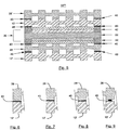
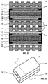
- FIG. 18 depicts a fuel cell having resin frames 115 between the membrane electrode assembly 136 and the separator plates 112, 128 to improve the durability of the membrane electrode assembly 136 and afford the correct spacing between the membrane electrode assembly 136 and separator plates 112, 128 during fuel cell assembly. In such a design, it is necessary have a seal between the separator plates 112, 128 and the resin frames 115.
- FIG. 19 depicts the membrane electrode assembly 136 having a cured or curable composition 140 at or near the peripheral portion 133 of the membrane electrode assembly 136.
- the composition 140 is useful for sealing and/or bonding different components of the fuel cell to one and the other.
- the present invention is not limited to having fuel cell components, such as or the membrane electrode assembly 136, with the composition 140 at or near the peripheral portion 133 of the membrane electrode assembly 136.
- the curable or curable composition 140 may be disposed at or near the peripheral portion 133 of the membrane electrode assembly 136 and cover peripheral edge portions 135 of the membrane electrode assembly 136.
- FIG. 21 shows a cross-sectional view of the basic elements of fuel cell 110 in which certain of the adjacent elements have a cured or curable composition 140 therebetween to provide a fuel assembly 110'.
- composition 140 seals and/or bonds the anode flow field plate 112 to the gas diffusion layer 118 or the membrane electrode assembly 136.
- the cathode field plate 128 is also sealed and/or bonded to the gas diffusion layer 126 or the membrane electrode assembly 136.
- fuel cell assembly 110' often has a preformed membrane electrode assembly 136 anode with the anode catalyst 120 and the cathode catalyst 124 disposed thereon.
- composition 140 disposed between the various components of the fuel cell assembly 110' may be the same composition or may be different compositions. Additionally, as depicted in FIG. 21 , composition 140 may seal and/or bond the cathode flow plate 128 to a component of a second fuel cell, such as a second anode flow field plate 112'. Further, as depicted in FIG. 21 , composition 140 may seal and/or bond the second anode flow field plate 112' to a component of a second fuel cell, such as a second membrane electrode assembly 136'. In such a manner, the fuel cell assembly 110' is formed of multiple fuel cells having components sealingly and/or adhesively adjoined to provide a multiple cell electrochemical device.
- FIG. 22 is a perspective view of a mold 48 useful for forming cured-in-place gaskets according to the present invention.
- the mold 48 includes an upper mold member 50, a lower mold member 136', and an injection port 52, interrelated as shown.
- composition 140 is disposed onto the lower mold member 136' to form a gasket thereat or thereon.
- the lower mold member 136' is desirably a fuel cell component, for example membrane electrode assembly 136.
- the present invention is not limited to the use of the membrane electrode assembly 36 as the bottom mold component, and other fuel cell components may be the bottom mold component.
- the injection port 52 is in fluid communication with the mold cavity 54.
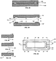
- FIG. 23 is a cross-sectional view of the mold 48 of FIG. 22 taken along the 23-23 axis.
- the upper mold member 50 includes a mold cavity 54. Liquid gasket-forming compositions may be introduced into the mold cavity 54 via the injection port 52.
- FIG. 24 is a partial-break-away view of the mold 48 of FIG. 23 .
- Mold member 50 includes a mating surface 56
- mold member 136' includes a mating surface 58.
- the mold members 50 and 136' may be aligned to one and the other, as depicted in FIG. 23 , such that the mating surfaces 56 and 58 are substantially juxtaposed to one and the other.
- a gasket 140 is removed from the mold cavity 54 and is attached to the mating surface 58.
- the mold cavity 54 is in the shape of a closed perimetric design. Although mold cavity 54 is depicted as a rounded rectangle in FIG. 25 , the present invention is not so limited and other shaped cavities may suitably be used. Further, while the cross-sectional shape of the mold cavity 54 is depicted as being rectangular or square in FIG. 24 , the present invention is not so limited and other cross-sectional shapes may suitably be used, such as circular, oval, or shaped geometries having extensions for improved sealing.
- the mold 50 may contain a second port 60.
- the second port 60 is in fluid communication with the mold cavity 54.
- the second port 60 may be used to degas the cavity 54 as it is being filled with the gasket-forming material. As the gasket-forming material in introduced into the cavity 54 via the port 52, air may escape via the second port 60 to degas the mold cavity 54.
- the size of the second port 60 is not limiting to the present invention. Desirably, the size, i.e., the cross-section extent, of the second port 60 is minimized to allow for the egress of air, but small enough to limit liquid flow of the gasket-forming material therethrough.
- the size of the second port 60 may be pin-hole sized where air can flow through while inhibiting substantial flow of liquid gasket-forming material.
- the present invention is not limited to the use of a single port 52 or a single port 60, and multiple ports may be used for the introduction of the gasket material and/or the venting of air.
- FIG. 26 is a cross-sectional view of the mold member 50 taken along the 26-26 axis of FIG. 25 .
- the injection port 52 may suitably be a cavity or bore in the mold member 50.
- the portion of the injection port 52 may be threaded (not shown) or have a valve (not shown) or a tubing or a hose (not shown) through which the gasket-forming material may be delivered.
- FIG. 27 is a cross-sectional view of the mold member 50 taken along the 27-27 axis of FIG. 25 .
- the port 60 may suitably be a cavity or bore in the mold member 50.
- the portion of the port 60 may have a valve (not shown) for controlling the egress of air and/or gasket-forming material.
- FIG. 28 is a cross-sectional view of the mold member 50 taken along the 28-28 axis of FIG. 25 .
- the mold cavity 54 is depicted as extending into the mold member 50 at its mating surface 56.
- FIG. 29 is a perspective view of a mold 48" useful for forming cured-in-place gaskets according to the present invention.
- the mold 48" includes an upper mold member 50, a lower mold member 70.
- the mold members 50 and 70 are fittable together in a fashion as discussed above and are configured such that a fuel cell component, such as membrane electrode assembly 136 may be disposed therebetween.
- the mold 48" of the present invention may be used to form the gasket 140 on peripheral portions of the opposed sides of the fuel cell component 136.
- the mold 48" of the present invention may also be used to form the gasket 140 on opposed sides and over the peripheral sides of the fuel cell component 136.
- FIG. 31 is a perspective view of the mold member 50, 70 depicting that the mold member 50, 70 may be made of or may include a transparent material.
- the mold member 50, 70 is transparent, i.e., transmissible or substantially transmissible, to actinic radiation, for example UV radiation.
- a cross-sectional view of the transparent mold member 50, 70 is depicted in FIG. 32 .
- the method of this aspect of the present invention may further include the step of degassing the cavity prior to injecting or while injecting the liquid, actinic radiation curable, gasket-forming composition.
- the step of degassing includes degassing through the second port 60, which is in fluid communication with the cavity 54.
- the liquid composition With the degassing of the cavity 54 and with the above-described fluid properties the liquid composition fully fills the cavity 54 without the need for excessive liquid handling pressures. Desirably, the liquid composition fully fills the cavity 54 at a fluid handling pressure of about 690 kPa (100 psig) or less.
- the mold members 50, 136' or 50, 70 may be released from one and the other to expose the gasket, after which the gasket 140 may be removed from the mold cavity 54.
- the gasket 140 is desirably disposed and/or affixed to the fuel cell component, for example membrane electrode assembly 136.
- top mold members 50, 70 as having a groove or mold cavity 54
- the present invention is not so limited.
- the bottom mold member 136', 70 and/or the fuel cell component, such as membrane exchange membrane 136 may have a groove or mold cavity for placement and formation of the seal in addition to or in replacement to the mold cavity 54 of the top mold members.
- the flow field plates of the fuel cell of the present invention may be bipolar plates, i.e., a plate having flow channels on opposed plate surfaces.
- the bipolar flow field plates 119 may be made from monopolar plates 112, 128 having a flow channel only on one side.
- the monopolar plates 112 and 128 may be secured to one and the other to from bipolar plates 119.
- the plates 112 and 128 are also sealed with the composition and by the methods of the present invention.
- telechelic-functional polyisobutylenes are more desirable, such as vinyl-terminated polyisobutylene.
- the telechelic-functional polyisobutylenes may react with an appropriate soluble organohydrogenpolysiloxane crosslinker to form a cured sealant.
- the cross-linking was done in the presence of a platinum catalyst, as follows: While hydrosilation-cured organic-based formulations are typically thermally cured using a platinum catalyst, such cures normally require at least one hour at an elevated temperature. Such curing conditions, however, limit continuous fabrication processes.
- the inventive liquid sealant compositions may be cured at or about room temperature within a short period of time, for example about 5 minutes or less. More desirably, the liquid composition is cured within 1 minute or less, for example, cured within 30 seconds or less.
- the cured sealant composition used in the present invention comprises an alkenyl terminated hydrocarbon oligomer; a polyfunctional alkenyl monomer selected from 1,9-decadiene, 1,2,4-trivinylcyclohexane and combinations thereof; a silyl hardener having at least about two silicon hydride functional groups; and a hydrosilylation catalyst.
- the alkenyl terminated hydrocarbon oligomer is preferably an alkenyl terminated polyisobutylene oligomer, for example an alkenyl terminated diallyl polyisobutylene oligomer. Desirably, only about one hydrogen atom is attached to any silicon atom in the silyl hardener.
- compositions used in the present invention have modified molecular structures, resulting in enhanced mechanical properties, cross-link densities and heats of reaction.
- the compositions of the present invention may be represented by the expression of (A-A + A f + B f ), where "A-A” represents the alkenyl groups of the alkenyl terminated polyisobutylene oligomer, e.g., a diallyl polyisobutylene, "A” represents an alkenyl group, "B” represents a Si-H group and "f” refers to the number of corresponding functional groups.
- both the alkenyl and hydride are difunctional, the polymerization yields a linear structure.
- the number of functional hydride groups in such a linear structure limits the overall functionality and cross-link density of the reacted network.
- TVCH One useful polyfunctional alkenyl monomer having three or more alkenyl groups is TVCH, which has the below chemical formula:
- TVCH is a low viscosity (1.3 mPas), tri-functional monomer. It has a molar mass of 162.3 grams per mole.
- the present invention is not limited to the use of a tri-functional monomer, and monomers with more than three alkenyl groups may suitably be used with the inventive compositions.
- One useful polyfunctional alkenyl monomer having two alkenyl groups is 1,9-decadiene (CAS No. 1647-16-1), which has a molecular weight of 138.25 grams per mole.
- the polyfunctional alkenyl monomer or a combination of alkenyl monomers may be present in amounts from about 0.01 weight percent to about 90 weight percent on a total composition basis. Desirably, the polyfunctional alkenyl monomer or a combination of alkenyl monomers may be present in amounts from about 0.1 weight percent to about 50 weight percent on a total composition basis. More desirably, the polyfunctional alkenyl monomer or a combination of alkenyl monomers may be present in amounts from about 1 weight percent to about 20 weight percent on a total composition basis, including from about 1 weight percent to about 10 weight percent on a total composition basis.
- Compatibility is an important issue and it is desirable to incorporate only those multi-functional monomers that are compatible with the difunctional oligomer of the resent invention. Multifunctional monomers that separated into two-phases are not compatible.
- TVCH has been completely compatible with the polyisobutylene resin of the present invention. At weight percentages of up to about 20 weight percent TVCH, the resulting compositions of the present invention form clear single-phase solutions when mixed with the alkenyl resin.
- Useful dialkenyl terminated linear poly(isobutylene) oligomers are commercially available from Kaneka Corporation, Osaka, Japan as EP200A, EP400A and EP600A. These three oligomers have the same functionality, but differ in molecular weight. EP200A, EP400A and EP600A have an approximate molecular weight (Mn) of 5,000; 10,000 and 20,000, respectively. The three oligomers also vary in viscosity from 944,300 centipoise ("cps"), 1,500,000 cps to 2,711,000 cps at 25°C, respectively.
- cps centipoise
- compositions of the present invention also include a silicone having at least two reactive silicon hydride functional groups, i.e., at least two Si-H groups.
- This component functions as a hardener or cross-linker for the alkenyl terminated polyisobutylene oligomer.
- the silicon-bonded hydrogen atoms in the cross-linking component undergo an addition reaction, which is referred to as hydrosilation, with the unsaturated groups in the reactive oligomer. Since the reactive oligomer contains at least two unsaturated groups, the silicone cross-linking component contains at least two silicon-bonded hydrogen atoms to achieve the final cross-linked structure in the cured product.
- the silicon-bonded organic groups present in the silicone cross-linking component may be selected from the same group of substituted and unsubstituted monovalent hydrocarbon radicals as set forth above for the reactive silicone component, with the exception that the organic groups in the silicone cross-linker should be substantially free of ethylenic or acetylenic unsaturation.
- the silicone cross-linker may have a molecular structure that can be straight chained, branched straight chained, cyclic or networked.
- the silicone cross-linking component may be selected from a wide variety of compounds, that desirably conforms to the formula below: where at least two of R 1 , R 2 and R 3 are H; otherwise R 1 , R 2 and R 3 can be the same or different and can be a substituted or unsubstituted hydrocarbon radical from C 1-20 , such as hydrocarbon radicals including alkyl, alkenyl, aryl, alkoxy, alkenyloxy, aryloxy, (meth)acryl or (meth)acryloxy; thus the SiH group may be attached at the terminal ends, attached as a pendent group along the siloxane backbone or both; R 4 can also be a substituted or unsubstituted hydrocarbon radical from C 1-20 , such as hydrocarbon radicals including a C 1-20 alkyl, alkenyl, aryl, alkoxy, alkenyloxy, aryloxy, (meth)acryl or (meth)acryloxy, and desirably is an alkyl
- R 2 and R 3 are not both hydrogen, e.g., R 1 is H and either R 2 or R 3 , but not both, is H. Desirably, R groups which are not H are methyl.
- the silicon hydride crosslinker should be present in amounts sufficient to achieve the desired amount of crosslinking and desirably in amounts of about 0.5 to about 40 percent by weight of the composition, more desirably from about 1 to about 20 percent by weight of the composition.
- a bicyclic cross-linking compound was prepared in a single step reaction and was compatible with functional hydrocarbon elastomers of the present invention. Two moles of 2,4,6,8-tetramethylcyclotetrasiloxane was reacted with one mole of 1,9-decadiene in the presence of a catalyst to yield a liquid hydride that is compatible with hydrocarbon oligomers and reacts with alkenyl oligomers to form elastomers that are useful for sealing fuel cells and the like. Such useful bicyclic cross-linking compounds are useful with the practice of the present invention.
- the present invention is not so limited and other bicyclic chemical structures, such as fluoroethers and the like, may suitably be used.
- the bicyclic crosslinker should be present in amounts sufficient to achieve the desired amount of crosslinking and desirably in amounts of about 0.5 to about 40 percent by weight of the composition, more desirably from about 1 to about 20 percent by weight of the composition.
- the structure of the bicyclic cross-linking agent of the present invention is the reaction product of 1,9-decadiene and 2,4,6,8-tetramethylcyclotetrasiloxane, as shown below:
- platinum catalysts include platinum or platinum-containing complexes such as the platinum hydrocarbon complexes described in U.S. Patent Nos. 3,159,601 and 3,159,662 ; the platinum alcoholate catalysts described in U.S. Patent No. 3,220,972 , the platinum complexes described in U.S. Patent No. 3,814,730 and the platinum chloride-olefin complexes described in U.S. Patent No. 3,516,946 .
- platinum or platinum-containing complex is dicarbonyl platinum cyclovinyl complex, platinum cyclovinyl complex, platinum divinyl complex, or combinations thereof.
- the platinum catalysts may be in sufficient quantity such that the composition cures at a temperature of about 130°C or less, desirably at a temperature of about 100°C or less, more desirably at a temperature of about 90°C or less. More desirably, a photoinitiator, such as one or more of the photoinitiators described below, so that compositions of the present invention may be cured by actinic radiation, such as ultraviolet radiation. Desirably, the liquid composition may be cured at or about room temperature within about 5 minutes or less. More desirably, the liquid composition is cured within 1 minute or less, for example, cured within 30 seconds or less.
- the liquid gasket-forming material may include actinic radiation curable (meth)acrylates, urethanes, polyethers, polyolefins, polyesters, copolymers thereof and combinations thereof.
- the curable material includes a (meth)acryloyl terminated material having at least two (meth)acryloyl pendant groups.
- the liquid gasket-forming material is a (meth)acryloyl-terminated poly(meth)acrylate.
- the (meth)acryloyl-terminated poly(meth)acrylate may desirably have a molecular weight from about 3,000 to about 40,000, more desirably from about 8,000 to about 15,000. Further, the (meth)acryloyl-terminated poly(meth)acrylate may desirably have a viscosity from about 200 Pas (200,000 cPs) to about 800 Pas (800,000 cPs) at 25°C (77°F), more desirably from about 450 Pas (450,000 cPs) to about 500 Pas (500,000 cPs). Details of such curable (meth)acryloyl-terminated materials may be found in European Patent Application No. EP 1 059 308 A1 to Nakagawa et al. , and are commercially available from Kaneka Corporation, Japan.
- a curable sealant may be used in a liquid injection molding process.
- the separator plates and resin frames may be stacked and aligned in the mold.
- the components are stacked from bottom to top in the order of cathode resin frame, cathode separator, anode separator, and anode resin frame, for example.
- These fuel cell components may contain one or more continuous pathways or gates that allow the sealant to pass through each component and bond the components while providing a molded seal at the top, bottom and/or on the edge.
- the sealant has a pumpable viscosity in its uncured state to allow it to assume the shape of the mold.
- the curable sealant is injected into the heated mold, or die, at an appropriate temperature to bond and seal fuel cell components.
- a curable sealant is used in a liquid injection molding process.
- the two separator plates are stacked and aligned in the mold so that the coolant pathway sides of the separators are facing each other.
- the separators may contain one or more continuous pathways that allow the sealant to bond each component while providing a molded seal at each end and/or on the edge.
- the sealant has a pumpable viscosity in its uncured state to allow it to assume the shape of the mold.
- the curable sealant is injected into the heated mold, or die, at the appropriate temperature to bond and seal the separators. In the case where there is no continuous pathway, an edge-sealed bipolar plate is produced.
- a curable sealant is used in a liquid injection molding process.
- a fuel cell component such as a resin frame, which may have one or more gates or holes, is placed in a mold, or die.
- the sealant has a pumpable viscosity in its uncured state to allow it to assume the shape of the mold.
- the sealant is injected into the heated mold, or die, at the appropriate temperature to cure the sealant.
- a resin frame with integrated seals on both sides, and possibly the edge, is provided.
- an MEA and a bonded assembly are stacked and aligned in a molding process.
- the bonded assembly may be composed of the resin frames and separators, as an example.
- the MEA and the bonded assembly may contain one or more continuous pathways that allow the sealant to bond each component while providing a molded seal at each end and/or on the edge.
- the sealant has a pumpable viscosity in its uncured state to allow it to assume the shape of the mold.
- the curable sealant is injected into the heated mold, or die, at the appropriate temperature to bond and seal the separators.
- the cured sealant composition used in the present invention includes an alkenyl terminated polyisobutylene oligomer, for example an alkenyl terminated diallyl polyisobutylene oligomer; optionally, a polyfunctional alkenyl monomer; a silyl hardener or cross-linker having at least one hydrogen atom bonded to a silicon atom; and a hydrosilylation catalyst. Desirably, only about one hydrogen atom bonded is to any silicon atom in the silyl hardener.
- the liquid composition may also include a photoinitiator.
- a photoinitiator may be employed herein to provide the benefits and advantages of the present invention to which reference is made above. Photoinitiators enhance the rapidity of the curing process when the photocurable compositions as a whole are exposed to electromagnetic radiation, such as actinic radiation.
- photoinitiators for use herein include, but are not limited to, photoinitiators available commercially from Ciba Specialty Chemicals, under the "IRGACURE” and “DAROCUR” trade names, specifically "IRGACURE” 184 (1-hydroxycyclohexyl phenyl ketone), 907 (2-methyl-1-[4-(methylthio)phenyl]-2-morpholino propan-1-one), 369 (2-benzyl-2-N,N-dimethylamino-1-(4-morpholinophenyl)-1-butanone), 500 (the combination of 1-hydroxy cyclohexyl phenyl ketone and benzophenone), 651 (2,2-dimethoxy-2-phenyl acetophenone), 1700 (the combination of bis(2,6-dimethoxybenzoyl-2,4,4-trimethyl pentyl) phosphine oxide and 2-hydroxy-2-methyl-1-phenyl-propan-1-one), and 819 [bis
- photoinitiators useful herein include alkyl pyruvates, such as methyl, ethyl, propyl, and butyl pyruvates, and aryl pyruvates, such as phenyl, benzyl, and appropriately substituted derivatives thereof.
- Photoinitiators particularly well-suited for use herein include ultraviolet photoinitiators, such as 2,2-dimethoxy-2-phenyl acetophenone (e.g., "IRGACURE” 651), and 2-hydroxy-2-methyl-1-phenyl-1-propane (e.g., "DAROCUR” 1173), bis(2,4,6-trimethyl benzoyl) phenyl phosphine oxide (e.g., "IRGACURE” 819), and the ultraviolet/visible photoinitiator combination of bis(2,6-dimethoxybenzoyl-2,4,4-trimethylpentyl) phosphine oxide and 2-hydroxy-2-methyl-1-phenyl-propan-1-one (e.g., "IRGACURE” 1700), as well as the visible photoinitiator bis( ⁇ 5 -2,4-Cyclopentadien-1-yl)-bis[2,6-difluoro-3-(1H-pyrrol-1-yl)phen
- Useful actinic radiation includes ultraviolet light, visible light, and combinations thereof. Desirably, the actinic radiation used to cure the liquid gasket-forming material has a wavelength from about 200 nm to about 1,000 nm.
- Useful UV includes, but is not limited to, UVA (about 320 nm to about 410 nm), UVB (about 290 nm to about 320 nm), UVC (about 220 nm to about 290 nm) and combinations thereof.
- Useful visible light includes, but is not limited to, blue light, green light, and combinations thereof. Such useful visible lights have a wavelength from about 450 nm to about 550 nm.
- the present invention is not limited to only the use of UV radiation and other energy sources such as heat, pressure, ultraviolet, microwave, ultrasonic or electromagnetic radiation may be used to initiate polymerization of one or more of the compositions. Additionally, the initiator could be active without an activating agent. Further, the initiation process may be applied before, during and/or after assembly.
- a release agent may be applied to the cavity 54 prior to the introduction of the liquid composition.
- the release agent if needed, helps in the easy removal of the cured gasket from the mold cavity.
- Useful mold release compositions include, but are not limited, to dry sprays such as polytetrafluoroethylene, and spray- on-oils or wipe-on-oils such as silicone or organic oils.
- Useful mold release compositions include, but are not limited, to compositions including C 6 to C 14 perfluoroalkyl compounds terminally substituted on at least one end with an organic hydrophilic group, such as betaine, hydroxyl, carboxyl, ammonium salt groups and combinations thereof, which is chemically and/or physically reactive with a metal surface.
- an organic hydrophilic group such as betaine, hydroxyl, carboxyl, ammonium salt groups and combinations thereof, which is chemically and/or physically reactive with a metal surface.
- a variety of mold releases are available, such as those marketed under Henkel's Frekote brand.
- the composition may further include a (meth)acryloyl-terminated compound having at least two (meth)acryloyl pendant groups selected from a (meth)acryloyl-terminated polyether, a (meth)acryloyl-terminated polyolefin, a (meth)acryloyl-terminated polyurethane, a (meth)acryloyl-terminated polyester, a (meth)acryloyl-terminated silicone, copolymers thereof, and combinations thereof.
- a (meth)acryloyl-terminated compound having at least two (meth)acryloyl pendant groups selected from a (meth)acryloyl-terminated polyether, a (meth)acryloyl-terminated polyolefin, a (meth)acryloyl-terminated polyurethane, a (meth)acryloyl-terminated polyester, a (meth)acryloyl-terminated silicone, copolymers thereof, and combinations thereof.
- the composition may further include a monofunctional (meth)acrylate.
- monofunctional (meth)acrylate monomers particularly desirable are hydroxypropyl methacrylate, 2-hydroxyethyl methacrylate, methyl methacrylate, tetrahydrofurfuryl methacrylate, cyclohexyl methacrylate, 2-aminopropyl methacrylate and the corresponding acrylates.
- the poly(meth)acrylate composition of the present invention may optionally include from about 0% to 90% poly(meth)acrylate polymer or copolymer, from about 0% to about 90% poly(meth)acrylate polymer or copolymer containing at least 2(meth)acrylate functional group; from about 0% by weight to about 90% by weight monofunctional and/or multifunctional (meth)acrylate monomers; from about 0% by weight to about 20% by weight photoinitiator; from about 0% by weight to about 20% by weight additives, such as antioxidants; from about 0% by weight to about 20% by weight fillers, such as fumed silica; from about 0% by weight to about 20% by weight rheology modifier; from about 0% by weight to about 20% by weight adhesion promoter; and/or from about 0% by weight to about 20% by weight fluorescent agents or pigments.
- the sealant composition 40 may include a polymerizable material not based on a linear PIB oligomer having terminal alkenyl or allyl group(s) and/or a cross-linking agent not having at least two hydrogen atoms each bonded to a silicone atom.
- the compositions of the present invention may include a branched PIB oligomer backbone.
- the PIB oligomer backbone either linear or branched, may include internal or pendent alkenyl or other functional groups with the ends being optionally free of terminal alkenyl or allyl group(s).
- the oligomeric backbone may include a co-polymer of PIB and another monomer, for example styrene.
- the co-polymer may be a random or block co-polymer.
- a linear or branched PIB polymer or co-polymer composition being free or substantially free of terminal alkenyl and/or allyl groups, may suitably be used herein.
- a linear or branched PIB polymer or co-polymer composition having one or more Si-CH 3 end and/or pendent groups at one or more ends may be used herein.
- the one or more end or pendent Si-CH 3 groups may be represented as: where R 5 , R 6 and R 7 , which can be the same or different, are alkyl can be the same or different and can be a substituted or unsubstituted hydrocarbon radical from C 1-20 such hydrocarbon radicals including alkyl, alkenyl, aryl, alkoxy, alkenyloxy, aryloxy, (meth)acryl or (meth)acryloxy, and provided that at least one of the R 5 , R 6 or R 7 is an alkyl group such as methyl.
- the use of a radical initiator may be used to abstract hydrogen from the alkyl, e.g., methyl, group.
- the resulting alkyl or methyl radical is reactive with compounds having alkene or vinyl functionality.
- Suitable compounds having alkene or vinyl functionality include, but are not limited to, the above-described polyfunctional alkenyl monomers, such as TVCH and/or 1,9-decadiene.
- the linear or branched PIB polymer or co-polymer composition is substantially free of any Si-H groups.
- a linear or branched PIB polymer or co-polymer composition may be capped at one or more ends with tetraalkyldisiloxane, desirably tetramethyldisiloxane, represented as: where R 8 , R 9 , R 10 and R 11 , which can be the same or different, are alkyl can be the same or different and can be a substituted or unsubstituted hydrocarbon radical from C 1-20 , such as hydrocarbon radicals including alkyl, alkenyl, aryl, alkoxy, alkenyloxy, aryloxy, (meth)acryl or (meth)acryloxy, desirably an alkyl group such as methyl.
- Such compositions may be cured with the above-described hydrosilylation catalysts and, optionally, may also include the above-described polyfunctional alkenyl monomers, such as TVCH or 1,9-decadiene.
- compositions of the present invention include linear or branched PIB polymer or co-polymer compositions having epoxide and/or vinyl ether terminal groups.
- Nonlimiting examples include PIB cycloaliphatic epoxide and PIB vinyl ether.
- a useful cycloaliphatic epoxide group includes where R 12 is C 1-20 alkyl or H.
- Useful PIB vinyl ether groups include
- compositions of the present invention may be cured or initiated for curing with a peroxide agent.
- a peroxide agent may be initiated by peroxy agents.
- Useful peroxy agents, including peroxy crosslinkers and initiators include the hydroperoxy polymerization initiators, for example, organic hydroperoxide initiators having the formula ROOH, where R generally is a hydrocarbon radical containing up to about 18 carbons, desirably an alkyl, aryl or aralkyl radical containing up to about 12 carbon atoms.
- hydroperoxides include cumene hydroperoxide, methylethylketone hydroperoxide as well as hydroperoxides formed by the oxygenation of various other hydrocarbons such as methylbutene, cetane and cyclohexane.
- peroxy initiators such as hydrogen peroxide or materials such as organic peroxides or peresters which hydrolyoize or decompose to form hydroperoxides may also be employed.
- a two-part sealant is used to bond separator plates 12, 112, 28, 128 and resin frames 15, 115.
- Part A of the sealant may contain a UV-activated initiator, which may be an acid, base, radical, anionic, and/or cationic initiator.
- Part B of the sealant may include a polymerizable monomer, oligomer, telechelic polymer, and/or functional polymer.
- the functional group could be, as an example, an epoxy, allyl, vinyl, (meth)acrylate, imide, amide or urethane.
- the resin frames 15, 115 are used for spacing within the fuel cell assembly 10, 110.
- the resin frames 15, 115 are placed on the gas pathway sides of the separators 12, 112, 28, 128 and seals are provided between each element.
- a separator plate 12, 112 typically a metal sheet, such as stainless steel, is desirably coated on both sides with part A of the sealant, cut, stamped to produce the necessary channels for reactive gas and coolant pathways, and activated with UV light.
- a resin frame 15, 115 is coated on at least one side with part B of the sealant and is assembled with the coated separator plate 12, 112 to provide an anode separator with bonded frame.
- a second separator plate 12, 112 typically a sheet of stainless steel, is desirably coated on both sides with part B of the sealant, cut, and stamped to produce the necessary channels for reactive gas and coolant pathways to form separator plate 28, 128.
- a second resin frame 15, 115 coated on at least one side with part A of the sealant and irradiated with UV light is assembled with the separator plate 28, 128 to provide a cathode separator with a bonded frame.
- the two manufacturing lines meet so that the bonded anode separator having an exposed coating of part A of the sealant on one of its side and the bonded cathode separator having an exposed coating of part B of the sealant on one of its sides are aligned, part A and part B of the sealant react and seal the fuel cell interfaces and to form bonded assembly.
- a two-part sealant is used to bond the separator plates 12, 112, 28, 128.
- Part A of the sealant contains a UV-activated initiator, which may be an acid, base, radical, anionic, and/or cationic initiator.
- Part B of the sealant is composed of a polymerizable monomer, oligomer, telechelic polymer, and/or functional polymer.
- the functional group could be, as an example, an epoxy, allyl, vinyl, (meth)acrylate, imide, amide or urethane.
- Part A is applied to the first separator plate, and part B is applied to the second separator plate.
- Part A is applied to the coolant pathway side of the anode separator 12, 112.
- Part B is applied to the coolant pathway side of the cathode separator 28, 128.
- part A undergoes UV irradiation to activate the initiator, followed by compression assembly with the cathode separator 28, 128.
- the separators 12, 112, 28, 128 are joined so that part A and part B react and seal the components to form the bipolar plate 119.
- a one-part sealant is used to bond separator plates 12, 112, 28, 128 and resin frames 15, 115.
- the sealant which may be composed of a UV-activated acid, base, radical, anionic, and/or cationic initiator and polymerizable monomer, oligomer, telechelic polymer and/or functional polymer, may be applied to one substrate, radiated with UV light, and compressed with a second substrate to form the seal.
- a two-part composition is used to bond and seal.
- Part A is applied to the first substrate.
- Part B is applied to the second substrate.
- the two substrates are combined and fixtured.
- Polymerization may be achieved in its simplest form by bringing the two substrates together, or by combining the substrates and using some additional form of energy, such as pressure, heat, ultrasonic, microwave or any combinations thereof.
- FIG. 35 depicts a system 80 for forming bonded assemblies, such as fuel cells or bonded fuel cell components, according the present invention.
- System 80 includes different stations 82, 84 for processing different fuel cell components.
- the system includes dispensers 86 and 88 for dispensing first and second parts, respectively, of a two-part sealant composition to coat different duel cell components.
- the system further includes sources 90 of energy, such as actinic radiation.
- a fuel cell stack may be prepared from a modular assembly and a gasket.
- a resin framed-MEA is produced in the first step.
- the anode and cathode resin frames are coated with a single component UV-activated sealant on one side of the resin frame.
- the sealant is activated by UV irradiation and the resin frames are fixtured on either side of the MEA.
- the separators are bonded to the resin frames using a two-part sealant.
- part A would be applied to substrate one
- part B would be applied to substrate two. Part A and B when combined could polymerize in one form of this invention.
- the resin framed-MEA is coated with part A on the resin frames, and then activated by UV irradiation. At the same time, the reactant gas sides of the separators are coated with part B.
- the resin framed-MEA is fixtured with the anode and cathode separators to produce a unit cell (anode separator, anode resin frame, MEA, cathode resin frame, and cathode separator).
- the unit cells are bonded together with a two-part sealant to form a module, containing a select number of unit cells, such as ten, for example.
- the unit cell is run through an operation to apply uncured polymer to the surface of one or more substrates.
- the coolant pathway side of the anode separator may be coated with part A and activated with UV irradiation.
- the coolant pathway side of the cathode separator may be coated with part B.
- the cells are stacked and fixtured to react part A with part B and seal the coolant pathways of the module.
- the separators at the ends of the module may not be coated in the process described above.
- a gasket is produced from sheet metal and a UV-activated sealant.
- a roll of sheet metal is cut, coated with a single component UV-activated sealant, and placed under UV light.
- the fuel cell stack may be assembled by alternating the gaskets with the modules until the desired number of cells in the stack is achieved. It is also envisioned that the resin frames and separators may be coated on both sides with the appropriate sealant, fixtured to the first component and then fixtured to the second component.
- a fuel cell stack may be prepared from a modular assembly and a gasket.
- a resin framed-MEA is produced in the first step. Two resin frames are coated with a single component UV-activated sealant on one side of the resin frame. The sealant is activated by UV irradiation and the resin frames are fixtured on either side of the MEA.
- a bonded separator is sealed to the resin framed-MEA using a two-part sealant. In a two-component system, part A of the sealant would be applied to a first substrate and part B of the sealant would be applied to a second substrate.
- Parts A and B of the sealant when combined, polymerize to form a bonded assembly according to one aspect of the present invention.
- an anode resin frame may be coated with part A of the sealant, and then activated by UV irradiation.
- a resin framed-MEA may be fixtured with the bonded separators to produce a unit cell (cathode separator, anode separator, anode resin frame, MEA, and cathode resin frame).
- the anode and cathode separators are bonded in another manufacturing line using a two-component sealant.
- the coolant pathway side of the anode separator is coated with part A of the sealant, and then activated by UV irradiation.
- the coolant pathway side of the cathode separator is coated with part B of the sealant, and fixtured to anode separator to react part A of the sealant with part B.
- the unit cells are bonded together with a two-part sealant to form a module, containing a select number of unit cells, such as by way of example ten.
- the unit cell is run through a coating operation.
- the gas pathway side of the cathode separator may be coated with part A of the sealant and activated with UV irradiation.
- the cathode resin frame may be coated with part B of the sealant.
- the unit cells are stacked and fixtured to react part A of the sealant with part B of the sealant to produce a module of bonded unit cells.
- the separator and resin frame at the ends of the module would not be coated in the process described above.
- a gasket is produced from sheet metal and a UV-activated sealant.
- a roll of sheet metal is cut, coated with a single component UV-activated sealant, and placed under UV light.
- the fuel cell stack may be assembled by alternating the gaskets with the modules until the desired number of cells in the stack is achieved.
- the resin frames and separators may be coated on both sides with the appropriate sealant, fixtured to the first component and then fixtured to the second component.
- TVCH was very effective in reducing the viscosity of alkenyl functional polyisobutylene resins. Viscosity reduction was observed in a 5,000; 10,000 and 20,000 number average molecular weight (Mn) alkenyl functional polyisobutylene. Details are shown in FIGs. 11 and 12 , Tables 1 and 2 for a 10,000 and 20,000 Mn alkenyl functional polyisobutylene for Inventive Composition Nos. 2 through 4 and 6 through 8 and for Comparative Composition Nos. 1 and 5. Table 1 Effect Of TVCH On Viscosity In A 10,000 Mn Alkenyl Functional Polyisobutylene Description Compar. Comp. 1 Inv. Comp. 2 Inv. Comp. 3 Inv. Comp.
- TVCH was effective in reducing the viscosity of the alkenyl functional polyisobutylene resins.
- the resultant inventive compositions did not separate, and TVCH concentrations of up to about 20 weight percent with the alkenyl functional polyisobutylene resins formed clear single-phase solutions or compositions.
- Formulations were prepared with and without TVCH while keeping the molar ratio of Si-H to alkenyl groups and platinum to alkenyl groups constant.
- Comparative Composition No. 9 shown below in Table 3 was prepared without any TVCH and cured. The composition had a heat of reaction of 29 joules per gram.
- Inventive Composition Nos. 10 through 14 which have different amounts of platinum catalyst, contained five weight percent of TVCH based on 100 grams of alkenyl polyisobutylene. The heat of reaction increased to about 83 joules per gram for the inventive compositions containing TVCH.
- Table 3 TVCH Addition To Difunctional Resins Description Compar. Comp. 9 Inv. Comp. 10 Inv Comp. 11 Inv. Comp. 12 Inv. Comp. 13 Inv. Comp.
- the peak exotherm temperature could be reduced from 137°C to approximately 92°C by increasing the amount of platinum from 20 to 60 mppm based on the concentration of alkenyl groups, as shown in FIG. 12 .
- This decrease in the peak exotherm temperature indicated that the activation temperature was significantly reduced, while the activation energy remained high.
- the experiments showed that the heat of reaction can be increased and the peak exotherm temperature can be reduced while maintaining a useful viscosity for screen-printing, liquid dispensing, liquid molding operations and other types of application methods.
- inhibitors can help reduce the change in viscosity as a function of time.
- inhibitors have the potential to diffuse or be extracted out of the composition when used within a fuel cell causing undesirable affects in the performance of the cell.
- These changes can include but are not limited to changes in the hydrophobic/hydrophilic balance and fuel cell catalyst, which are reflected in a decrease in the overall output of the device.
- TVCH The unexpected stabilizing affects of TVCH allow the use of higher concentrations of platinum catalyst, the ability to manufacture compositions without gelling and the ability to improve stability using moieties that cross-link into the polymer network thereby reducing the diffusion or extraction of the species in the final application.
- TVCH can also be used along with inhibitors that do not cross-link into the final network at low levels.
- Example 3 Formulated Physical Property Data (Compression Set, Hardness & Mechanical Properties) :
- compositions 25 through 30 were prepared using a constant ratio of TVCH to alkenyl terminated PIB while varying the amount of Si-H to the total number of alkenyl groups by varying the polyalkyl hydrogen siloxane content to measure the change in physical, mechanical and thermodynamic properties.
- Tables 6 and 7 and FIG. 13 show that as the stoichiometric imbalance increased, the ratio of Si-H to alkenyl groups increased, compression set values decreased while mechanical properties increased.
- Optimal properties were obtained at a stoichiometric imbalance of approximately 1.4 to 1.0 (Si-H to alkenyl groups).
- the absolute value of the compression set decreased dramatically to 8%, which is very low for an elastomer and unexpected.
- Comparative Composition No. 31 was prepared with the alkenyl terminated PIB and the polyalkyl hydrogen siloxane at a molar ratio of 1.5:1 of Si-H to the total number of alkenyl groups. Comparative Composition No. 31 did not contain any TVCH. An inhibitor -- 3,5-dimethyl-1-hexyne-ol -- was added to Comparative Composition No. 31 to inhibit the cure rate of the composition so that the compression test could be performed. Without any inhibitor, the composition gelled within a couple of minutes. Comparative Composition No. 31 was observed to have a compression set of 22%. As shown in Table 6, Inventive Composition No. 30 had significantly improved compression set properties as compared to Comparative Composition No. 31.
- the infrared spectrums were compared for compositions with a 1:1 and 1.5:1 stoichiometric ratio using a mathematical subtraction method to validate that an excess concentration of Si-H is present in the cured network containing an excess amount of Si-H compare to a stoichiometric network.
- the subtraction spectrum was consistent with the spectra for the neat cross-linker from 4000 to 1200 cm -1 .
- Example 4 Inventive Compositions With 1,9-Decadiene:
- Inventive Composition No. 32 was prepared as shown below in Table 8 with 1,9-decadiene and a bicyclic decadiene cross-linker. This composition demonstrated excellent reaction data, e.g., exothermic data and heat of reaction.
- Inventive base formulations were prepared from the components shown in Table 9 and as follows below: Table 9 Polyisobutylene Sealant Base Formulation (Inventive Base Formulation A) Supplier Chemical Description Wt % Kaneka Epion EP200A 64.50% Kaneka Epion EP400A 21.50% Degussa TVCH reactive diluent 1.17% Kaneka CR300 Crosslinker 12.83% Total: 100.00% EP200A and EP400A are resins supplied by Kaneka. CR300 is a phenylsiloxane crosslinker supplied by Kaneka.
- a UV-activatable platinum complex was used and the hydrosilation reaction was initiated upon irradiation and continues after removal of the radiation (post cure).
- UV-labile platinum complexes examined include: Platinum (II) 2,4-pentanedionate (“Pt(acac) 2 ”) (Trimethyl)methylcyclopentadienylplatinum (IV) (“TMMCP”)
Landscapes
- Chemical & Material Sciences (AREA)
- Chemical Kinetics & Catalysis (AREA)
- Electrochemistry (AREA)
- General Chemical & Material Sciences (AREA)
- Engineering & Computer Science (AREA)
- Manufacturing & Machinery (AREA)
- Life Sciences & Earth Sciences (AREA)
- Sustainable Development (AREA)
- Sustainable Energy (AREA)
- Fuel Cell (AREA)
- Sealing Material Composition (AREA)
Claims (12)
- Procédé de formation d'une pile à combustible comprenant :la fourniture d'un composant de pile à combustible ;la fourniture d'un moule ayant une cavité ;le positionnement du moule de sorte que la cavité est en communication fluidique avec le composant de pile à combustible ;l'application d'un agent d'étanchéité liquide durcissable dans la cavité ; etle durcissement de la composition, dans lequel la composition d'agent d'étanchéité comprend ;un oligomère d'hydrocarbure à terminaison alcényle ;un monomère alcényle polyfonctionnel choisi parmi le 1,9-décadiène, le 1,2,4-trivinylcyclohexane et des combinaisons de ceux-ci.un agent de durcissement silyle ayant au moins environ deux groupes fonctionnels d'hybride de silicium ; etun catalyseur d'hydrosilylation.
- Procédé selon la revendication 1, dans lequel le composant de pile à combustible est choisi parmi le groupe constitué d'une plaque à champ d'écoulement de cathode, d'une plaque à champ d'écoulement d'anode, d'un cadre en résine, d'une couche de diffusion de gaz, d'une couche de catalyseur d'anode, d'une couche de catalyseur de cathode, d'un électrolyte à membrane, d'un cadre d'ensemble membrane électrode, et des combinaisons de ceux-ci.
- Procédé selon la revendication 1, dans lequel le composant de pile à combustible est un ensemble membrane électrode comprenant une couche de diffusion de gaz.
- Procédé selon la revendication 3, dans lequel l'étape d'application de l'agent d'étanchéité comprend en outre :l'application d'une pression sur l'agent d'étanchéité de sorte que l'agent d'étanchéité pénètre dans la couche de diffusion de gaz.
- Procédé selon la revendication 3, dans lequel l'étape d'application de l'agent d'étanchéité comprend en outre :l'application de l'agent d'étanchéité de sorte qu'un bord de l'ensemble membrane électrode est entièrement recouvert par l'agent d'étanchéité.
- Procédé selon la revendication 1, dans lequel l'étape de durcissement de la composition comprend :le durcissement thermique de l'agent d'étanchéité à une température d'environ 130 °C ou moins.
- Procédé selon la revendication 1, dans lequel l'étape de durcissement de la composition comprend :la fourniture d'un rayonnement actinique pour durcir l'agent d'étanchéité à environ la température ambiante.
- Procédé selon la revendication 7, dans lequel le moule est transmissif au rayonnement actinique.
- Procédé selon la revendication 7, dans lequel la composition d'agent d'étanchéité durcissable comprend un matériau durcissable par rayonnement actinique choisi parmi le groupe constitué du (méth)acrylate, de l'uréthane, du polyéther, de la polyoléfine, du polyester, des copolymères de ceux-ci et de leurs combinaisons.
- Procédé selon la revendication 7, dans lequel la composition d'agent d'étanchéité durcissable comprend un polyisobutylène à fonction téléchélique, un agent de réticulation silyle
ayant au moins environ deux groupes fonctionnels d'hybride de silicium, un catalyseur de platine et un photoinitiateur. - Procédé selon la revendication 1, dans lequel l'oligomère d'hydrocarbure à terminaison alcényle comprend un oligomère de polyisobutylène à terminaison alcényle.
- Ensemble membrane électrode ayant une composition d'agent d'étanchéité durcie disposée sur des parties périphériques de l'ensemble, dans lequel la composition d'agent d'étanchéité durcie comprend :un oligomère de polyisobutylène diallyle à terminaison alcényle ;un monomère alcényle polyfonctionnel choisi parmi le 1,9-décadiène, 1,2,4-trivinylcyclohexane et des combinaisons de ceux-ci ;un agent de durcissement silyle ayant au moins environ deux groupes fonctionnels d'hybride de silicium ;un catalyseur d'hydrosilylation ; etun agent d'initiation ou de réticulation de peroxyde.
Applications Claiming Priority (5)
| Application Number | Priority Date | Filing Date | Title |
|---|---|---|---|
| US75945606P | 2006-01-17 | 2006-01-17 | |
| US75945206P | 2006-01-17 | 2006-01-17 | |
| US75938006P | 2006-01-17 | 2006-01-17 | |
| US11/549,331 US20090162715A1 (en) | 2005-10-20 | 2006-10-13 | Polyisobutylene compositions with improved reactivity and properties for bonding and sealing fuel cell components |
| PCT/US2007/001232 WO2007084561A2 (fr) | 2006-01-17 | 2007-01-17 | Ensemble pile à combustible assemblé, procédés, systèmes et compositions d'agent d'étanchéité pour le produire |
Publications (3)
| Publication Number | Publication Date |
|---|---|
| EP2033248A2 EP2033248A2 (fr) | 2009-03-11 |
| EP2033248A4 EP2033248A4 (fr) | 2012-08-08 |
| EP2033248B1 true EP2033248B1 (fr) | 2017-12-27 |
Family
ID=38288209
Family Applications (1)
| Application Number | Title | Priority Date | Filing Date |
|---|---|---|---|
| EP07718267.3A Active EP2033248B1 (fr) | 2006-01-17 | 2007-01-17 | L'assemblage d'elektrode et la méthode pour former un pile à combustible |
Country Status (5)
| Country | Link |
|---|---|
| US (1) | US20090000732A1 (fr) |
| EP (1) | EP2033248B1 (fr) |
| KR (1) | KR20080094059A (fr) |
| CA (1) | CA2637064C (fr) |
| WO (1) | WO2007084561A2 (fr) |
Families Citing this family (47)
| Publication number | Priority date | Publication date | Assignee | Title |
|---|---|---|---|---|
| WO2006071234A1 (fr) | 2004-12-28 | 2006-07-06 | Utc Fuel Cells, Llc | Structure d'ensemble membrane / electrodes (mea) contenant une couche catalysee |
| US8066288B2 (en) | 2005-10-20 | 2011-11-29 | Henkel Corporation | Components comprising polyisobutylene compositions |
| WO2007084472A2 (fr) * | 2006-01-17 | 2007-07-26 | Henkel Corporation | Composants de pile à combustible à agent d'étanchéité intégré et procédés et systèmes pour les produire |
| KR101465804B1 (ko) * | 2006-01-17 | 2014-11-26 | 헨켈 유에스 아이피 엘엘씨 | Uv 경화성 연료 전지 실란트 및 그로부터 형성된 연료 전지 |
| JP5217230B2 (ja) * | 2007-04-27 | 2013-06-19 | トヨタ自動車株式会社 | 燃料電池用スタックおよび燃料電池搭載車両 |
| JP5017080B2 (ja) * | 2007-12-26 | 2012-09-05 | 東芝燃料電池システム株式会社 | 燃料電池用の単電池 |
| WO2010047693A1 (fr) * | 2008-10-22 | 2010-04-29 | Utc Fuel Cells, Llc | Plaque poreuse de champ d’écoulement pour commande de répartition d’humidité dans une pile à combustible |
| DE102009039903A1 (de) * | 2009-09-03 | 2011-03-10 | Daimler Ag | Brennstoffzellenstapelabschnitt sowie Verfahren zur Montage des Brennstoffzellenabschnitts |
| US9377207B2 (en) | 2010-05-25 | 2016-06-28 | 7Ac Technologies, Inc. | Water recovery methods and systems |
| EP2668689B1 (fr) * | 2011-01-28 | 2017-06-14 | Audi AG | Joint de pile à combustible |
| KR101337905B1 (ko) * | 2011-09-21 | 2013-12-09 | 기아자동차주식회사 | 초음파 진동 접합을 이용한 연료전지 막-전극 접합체 제조 방법 |
| US9101875B2 (en) | 2012-06-11 | 2015-08-11 | 7Ac Technologies, Inc. | Methods and systems for turbulent, corrosion resistant heat exchangers |
| KR101361233B1 (ko) * | 2012-09-05 | 2014-02-11 | 현대자동차주식회사 | 연료전지스택의 막전극접합체 어셈블리 제조설비 |
| WO2014089164A1 (fr) | 2012-12-04 | 2014-06-12 | 7Ac Technologies, Inc. | Méthodes et systèmes de refroidissement de bâtiments avec des charges thermiques élevées grâce à des refroidisseurs à dessiccant |
| EP3428549B1 (fr) | 2013-03-01 | 2020-06-03 | 7AC Technologies, Inc. | Systèmes de climatisation à absorbeur d'humidité |
| ES2761585T3 (es) | 2013-03-14 | 2020-05-20 | 7Ac Tech Inc | Sistema de aire acondicionado con desecante líquido dividido |
| US9709285B2 (en) | 2013-03-14 | 2017-07-18 | 7Ac Technologies, Inc. | Methods and systems for liquid desiccant air conditioning system retrofit |
| CN105229835B (zh) * | 2013-05-16 | 2017-10-13 | 日产自动车株式会社 | 燃料电池用的分隔件组件的制造装置和制造方法 |
| CN110715390B (zh) | 2013-06-12 | 2022-02-25 | 艾默生环境优化技术有限公司 | 用于具有冷流体回路的建筑物的空气调节系统 |
| KR102641608B1 (ko) | 2014-03-20 | 2024-02-28 | 코프랜드 엘피 | 옥상 액체 데시컨트 시스템 및 방법 |
| DE102014208445A1 (de) * | 2014-05-06 | 2015-11-12 | Volkswagen Ag | Bipolarplatte, Brennstoffzelle und Verfahren zur Herstellung der Bipolarplatte |
| DE102014210370A1 (de) * | 2014-06-02 | 2015-12-03 | Volkswagen Aktiengesellschaft | Befeuchter, Platte, Vorrichtung und Kraftfahrzeug |
| EP3221648B1 (fr) | 2014-11-21 | 2020-01-08 | 7AC Technologies, Inc. | Système de climatisation à déshydratant liquide |
| KR102544142B1 (ko) | 2015-07-30 | 2023-06-15 | 가부시끼가이샤 쓰리본드 | 광경화성 수지 조성물, 연료전지 및 밀봉 방법 |
| JP6828230B2 (ja) * | 2015-08-18 | 2021-02-10 | 株式会社スリーボンド | 燃料電池用光硬化性シール剤、燃料電池およびシール方法 |
| US11261301B2 (en) * | 2015-09-02 | 2022-03-01 | Threebond Co., Ltd. | Photocurable resin composition, fuel cell, and sealing method |
| JP6884979B2 (ja) | 2016-03-09 | 2021-06-09 | 株式会社スリーボンド | 硬化性樹脂組成物、燃料電池およびシール方法 |
| WO2018003855A1 (fr) | 2016-06-28 | 2018-01-04 | 株式会社スリーボンド | Composition de résine durcissable, pile à combustible, et procédé d'étanchéité |
| WO2018190417A1 (fr) * | 2017-04-14 | 2018-10-18 | 株式会社スリーボンド | Composition de résine polymérisable, pile à combustible l'utilisant et procédé d'étanchéité |
| CN111373202B (zh) | 2017-11-01 | 2021-11-26 | 艾默生环境优化技术有限公司 | 液体干燥剂空调系统中膜模块中液体干燥剂的均匀分布的方法和设备 |
| EP3704415A4 (fr) | 2017-11-01 | 2021-11-03 | 7AC Technologies, Inc. | Système de réservoir pour système de conditionnement d'air à déshydratant liquide |
| US11022330B2 (en) | 2018-05-18 | 2021-06-01 | Emerson Climate Technologies, Inc. | Three-way heat exchangers for liquid desiccant air-conditioning systems and methods of manufacture |
| JP6518821B1 (ja) * | 2018-06-06 | 2019-05-22 | 日本碍子株式会社 | セルスタック装置 |
| SE544014C2 (en) * | 2018-06-26 | 2021-11-02 | Powercell Sweden Ab | Manufacturing arrangement for a fuel cell stack and method for manufactur-ing a fuel cell stack |
| US11865750B2 (en) | 2018-08-10 | 2024-01-09 | Mitsui Chemicals, Inc. | Composite structure and housing for electronic device |
| KR102845708B1 (ko) * | 2019-05-16 | 2025-08-12 | 현대자동차주식회사 | 연료전지용 탄성체 셀 프레임 및 그 제조방법과 이를 이용한 연료전지 스택 |
| CN110581287B (zh) * | 2019-09-09 | 2021-01-19 | 上海骥翀氢能科技有限公司 | 质子交换膜燃料电池免粘焊密封结构的金属双极板 |
| EP3828974B1 (fr) * | 2019-11-29 | 2026-01-28 | AVL List GmbH | Ensemble de cellules d'unité pour piles de cellules à combustible et son procédé de fabrication |
| DE102020216095A1 (de) * | 2020-12-17 | 2022-06-23 | Robert Bosch Gesellschaft mit beschränkter Haftung | Bipolarplatte, elektrochemische Zelle und Verfahren zum Herstellen einer elektrochemischen Zelle |
| CN113711410A (zh) * | 2021-03-31 | 2021-11-26 | 宁德新能源科技有限公司 | 电极组件及电子装置 |
| DE102021209651A1 (de) | 2021-09-02 | 2023-03-02 | Robert Bosch Gesellschaft mit beschränkter Haftung | Verfahren zur Herstellung einer Verbindungskomponente |
| CN114335591A (zh) * | 2021-12-28 | 2022-04-12 | 郝建强 | 氢燃料电池用低硬度热固化聚异丁烯密封胶 |
| US20230291042A1 (en) * | 2022-03-09 | 2023-09-14 | Duracell U.S. Operations, Inc. | Battery cell seal, seal assembly for battery cell, and battery cell comprising a cross-linked grommet |
| CA3251547A1 (fr) * | 2022-03-11 | 2023-09-14 | Illuming Power Inc. | Procédé de fabrication d'un séparateur de pile à combustible à joint élastomère intégré |
| US20240097154A1 (en) * | 2022-09-10 | 2024-03-21 | Godfrey & Wing, Llc | Sealant resin composition for flexible graphite plate impregnation |
| DE102023204498A1 (de) | 2023-05-15 | 2024-11-21 | Robert Bosch Gesellschaft mit beschränkter Haftung | Schablone und Herstellungsverfahren zum Herstellen einer Dichtung für einen elektrochemischen Energiewandler |
| DE102024202054A1 (de) * | 2024-03-05 | 2025-09-11 | Robert Bosch Gesellschaft mit beschränkter Haftung | Verfahren zur Herstellung einer Dichtung auf einem Substrat |
Family Cites Families (44)
| Publication number | Priority date | Publication date | Assignee | Title |
|---|---|---|---|---|
| US3220972A (en) * | 1962-07-02 | 1965-11-30 | Gen Electric | Organosilicon process using a chloroplatinic acid reaction product as the catalyst |
| US3159662A (en) * | 1962-07-02 | 1964-12-01 | Gen Electric | Addition reaction |
| US3159601A (en) * | 1962-07-02 | 1964-12-01 | Gen Electric | Platinum-olefin complex catalyzed addition of hydrogen- and alkenyl-substituted siloxanes |
| US3516946A (en) | 1967-09-29 | 1970-06-23 | Gen Electric | Platinum catalyst composition for hydrosilation reactions |
| US3814730A (en) | 1970-08-06 | 1974-06-04 | Gen Electric | Platinum complexes of unsaturated siloxanes and platinum containing organopolysiloxanes |
| US4531339A (en) | 1984-04-23 | 1985-07-30 | The Firestone Tire & Rubber Company | Channel end cap |
| US5264299A (en) * | 1991-12-26 | 1993-11-23 | International Fuel Cells Corporation | Proton exchange membrane fuel cell support plate and an assembly including the same |
| US5885514A (en) * | 1996-12-09 | 1999-03-23 | Dana Corporation | Ambient UVL-curable elastomer mold apparatus |
| DE19713250C2 (de) * | 1997-03-29 | 2002-04-18 | Ballard Power Systems | Elektrochemischer Energiewandler mit Polymerelektrolytmembran |
| ATE216138T1 (de) * | 1997-07-16 | 2002-04-15 | Ballard Power Systems | Elastische dichtung für eine membranelektrodenanordnung in einer elektrochemischen brennstoffzelle und herstellungsverfahren dafür |
| DE19756620A1 (de) * | 1997-12-19 | 1999-06-24 | Bosch Gmbh Robert | Verfahren zur Herstellung eines Absorbermaterials |
| CA2321784A1 (fr) | 1998-02-27 | 1999-09-02 | Kaneka Corporation | Polymere et composition solidifiable |
| WO1999053559A1 (fr) | 1998-04-14 | 1999-10-21 | Three Bond Co., Ltd. | Materiau d'etancheite pour pile a combustible |
| US6337120B1 (en) * | 1998-06-26 | 2002-01-08 | Nok Corporation | Gasket for layer-built fuel cells and method for making the same |
| EP0989430A3 (fr) * | 1998-09-24 | 2000-05-24 | LG Cable & Machinery Ltd. | Procédé de fabrication de diodes laser, de modules optiques émetteur/récepteur et leurs méthodes d'alignement |
| US6159628A (en) | 1998-10-21 | 2000-12-12 | International Fuel Cells Llc | Use of thermoplastic films to create seals and bond PEM cell components |
| US6165634A (en) | 1998-10-21 | 2000-12-26 | International Fuel Cells Llc | Fuel cell with improved sealing between individual membrane assemblies and plate assemblies |
| KR100341402B1 (ko) * | 1999-03-09 | 2002-06-21 | 이종훈 | 고체산화물 연료전지의 단전지와 스택구조 |
| US6231053B1 (en) * | 1999-06-11 | 2001-05-15 | Nok Corporation | Gasket for fuel cell |
| EP1197522A4 (fr) * | 1999-06-29 | 2002-09-25 | Kaneka Corp | Composition conductrice ayant une excellente stabilite de stockage a haute temperature et rouleau conducteur obtenu a partir de cette composition |
| EP1073138B1 (fr) * | 1999-07-26 | 2012-05-02 | Tigers Polymer Corporation | Structure d'étanchéité pour pile à combustible et procédé de formation du joint d'étanchéité en caoutchouc |
| JP4539896B2 (ja) * | 1999-09-17 | 2010-09-08 | 独立行政法人産業技術総合研究所 | プロトン伝導性膜、その製造方法及びそれを用いた燃料電池 |
| US6656580B2 (en) * | 1999-12-17 | 2003-12-02 | Henkel Loctite Corporation | Impregnation of a graphite sheet with a sealant |
| JP4743356B2 (ja) * | 2000-05-15 | 2011-08-10 | 日清紡ホールディングス株式会社 | 燃料電池セパレータの製造方法、燃料電池セパレータ及び固体高分子型燃料電池 |
| US6773758B2 (en) * | 2000-05-17 | 2004-08-10 | Kaneka Corporation | Primer composition and bonding method |
| JP3571687B2 (ja) * | 2000-12-07 | 2004-09-29 | 本田技研工業株式会社 | シール一体型セパレータの製造方法 |
| US20030031911A1 (en) * | 2001-04-13 | 2003-02-13 | Rosalyn Ritts | Biocompatible membranes and fuel cells produced therewith |
| US6852439B2 (en) * | 2001-05-15 | 2005-02-08 | Hydrogenics Corporation | Apparatus for and method of forming seals in fuel cells and fuel cell stacks |
| DE10125360A1 (de) * | 2001-05-23 | 2002-12-05 | Wacker Chemie Gmbh | Verwendung von zu degradationsstabilen Siliconkautschuken vernetzbaren Massen als Dichtungsmassen in Brenntstoffzellen |
| JP3786185B2 (ja) * | 2001-06-22 | 2006-06-14 | 信越化学工業株式会社 | 固体高分子型燃料電池セパレータシール用ゴム組成物及びこれを用いたシール材並びに固体高分子型燃料電池セパレータ |
| JP3888233B2 (ja) | 2001-09-17 | 2007-02-28 | トヨタ自動車株式会社 | 燃料電池電極の製造方法と製造装置 |
| US20030116185A1 (en) * | 2001-11-05 | 2003-06-26 | Oswald Robert S. | Sealed thin film photovoltaic modules |
| US6884537B2 (en) | 2001-12-20 | 2005-04-26 | Freudenberg-Nok General Partnership | Structural seal for a fuel cell |
| US6989214B2 (en) | 2002-11-15 | 2006-01-24 | 3M Innovative Properties Company | Unitized fuel cell assembly |
| US6979383B2 (en) | 2002-12-17 | 2005-12-27 | 3M Innovative Properties Company | One-step method of bonding and sealing a fuel cell membrane electrode assembly |
| US7670709B2 (en) | 2002-12-31 | 2010-03-02 | Freudenberg-Nok General Partnership | Fuel cell seal with integral bridge |
| US20070009780A1 (en) | 2003-02-03 | 2007-01-11 | Freudenberg-Nok General Partnership | Sealing of multi-height surfaces |
| JP4155054B2 (ja) * | 2003-02-18 | 2008-09-24 | 日産自動車株式会社 | バイポーラ電池 |
| TW200502372A (en) * | 2003-02-25 | 2005-01-16 | Kaneka Corp | Curing composition and method for preparing same, light-shielding paste, light-shielding resin and method for producing same, package for light-emitting diode, and semiconductor device |
| WO2004107476A2 (fr) * | 2003-05-29 | 2004-12-09 | Henkel Corporation | Procede et composition pour lier et fermer hermetiquement des composants de pile a combustible |
| US6942941B2 (en) * | 2003-08-06 | 2005-09-13 | General Motors Corporation | Adhesive bonds for metalic bipolar plates |
| JP4959343B2 (ja) | 2004-01-22 | 2012-06-20 | ヘンケル コーポレイション | 燃料電池用の低表面エネルギー基体を結合および封止するための重合性組成物 |
| US20050173833A1 (en) * | 2004-02-05 | 2005-08-11 | Dale Cummins | Method of forming bipolar plate modules |
| KR100631146B1 (ko) * | 2004-06-12 | 2006-10-02 | 동원이엠 주식회사 | 연료전지용 바이폴라 플레이트의 제조방법 |
-
2007
- 2007-01-17 EP EP07718267.3A patent/EP2033248B1/fr active Active
- 2007-01-17 KR KR1020087019940A patent/KR20080094059A/ko not_active Ceased
- 2007-01-17 CA CA2637064A patent/CA2637064C/fr active Active
- 2007-01-17 US US12/161,173 patent/US20090000732A1/en not_active Abandoned
- 2007-01-17 WO PCT/US2007/001232 patent/WO2007084561A2/fr not_active Ceased
Non-Patent Citations (1)
| Title |
|---|
| None * |
Also Published As
| Publication number | Publication date |
|---|---|
| EP2033248A4 (fr) | 2012-08-08 |
| CA2637064C (fr) | 2015-11-24 |
| US20090000732A1 (en) | 2009-01-01 |
| EP2033248A2 (fr) | 2009-03-11 |
| WO2007084561A3 (fr) | 2007-10-11 |
| WO2007084561A2 (fr) | 2007-07-26 |
| KR20080094059A (ko) | 2008-10-22 |
| CA2637064A1 (fr) | 2007-07-26 |
Similar Documents
| Publication | Publication Date | Title |
|---|---|---|
| EP2033248B1 (fr) | L'assemblage d'elektrode et la méthode pour former un pile à combustible | |
| CN101401240B (zh) | 粘结的燃料电池组件,方法,体系和生产它的密封剂组合物 | |
| EP1974411B1 (fr) | Agents d'étanchéité durcissables par uv pour piles à combustible et piles à combustible formées avec ces agents | |
| JP6469140B2 (ja) | 燃料電池部品を形成するための方法、燃料電池部品を形成するためのシステムおよび電気化学電池 | |
| EP1974402B1 (fr) | Ensemble pile à combustible collé et procédés et systèmes pour la fabrication de celui-ci |
Legal Events
| Date | Code | Title | Description |
|---|---|---|---|
| PUAI | Public reference made under article 153(3) epc to a published international application that has entered the european phase |
Free format text: ORIGINAL CODE: 0009012 |
|
| 17P | Request for examination filed |
Effective date: 20080728 |
|
| AK | Designated contracting states |
Kind code of ref document: A2 Designated state(s): AT BE BG CH CY CZ DE DK EE ES FI FR GB GR HU IE IS IT LI LT LU LV MC NL PL PT RO SE SI SK TR |
|
| AX | Request for extension of the european patent |
Extension state: AL BA HR MK RS |
|
| RIN1 | Information on inventor provided before grant (corrected) |
Inventor name: EINSLA, BRIAN, RUSSEL Inventor name: NAKOS, STEVEN, THOMAS Inventor name: WOODS, JOHN, G. Inventor name: JACOBINE, ANTHONY, FRANCIS Inventor name: WELSH, KEVIN, JAMES Inventor name: BURDZY, MATTHEW, PETER |
|
| REG | Reference to a national code |
Ref country code: DE Ref legal event code: R079 Ref document number: 602007053532 Country of ref document: DE Free format text: PREVIOUS MAIN CLASS: H01M0008020000 Ipc: H01M0002080000 |
|
| A4 | Supplementary search report drawn up and despatched |
Effective date: 20120705 |
|
| DAX | Request for extension of the european patent (deleted) | ||
| RIC1 | Information provided on ipc code assigned before grant |
Ipc: H01M 8/02 20060101ALI20120705BHEP Ipc: H01M 8/24 20060101ALI20120705BHEP Ipc: H01M 2/08 20060101AFI20120705BHEP |
|
| RAP1 | Party data changed (applicant data changed or rights of an application transferred) |
Owner name: HENKEL US IP LLC |
|
| RAP1 | Party data changed (applicant data changed or rights of an application transferred) |
Owner name: HENKEL IP & HOLDING GMBH |
|
| 17Q | First examination report despatched |
Effective date: 20161123 |
|
| GRAP | Despatch of communication of intention to grant a patent |
Free format text: ORIGINAL CODE: EPIDOSNIGR1 |
|
| INTG | Intention to grant announced |
Effective date: 20170726 |
|
| GRAS | Grant fee paid |
Free format text: ORIGINAL CODE: EPIDOSNIGR3 |
|
| GRAA | (expected) grant |
Free format text: ORIGINAL CODE: 0009210 |
|
| AK | Designated contracting states |
Kind code of ref document: B1 Designated state(s): AT BE BG CH CY CZ DE DK EE ES FI FR GB GR HU IE IS IT LI LT LU LV MC NL PL PT RO SE SI SK TR |
|
| REG | Reference to a national code |
Ref country code: GB Ref legal event code: FG4D |
|
| REG | Reference to a national code |
Ref country code: CH Ref legal event code: EP |
|
| REG | Reference to a national code |
Ref country code: AT Ref legal event code: REF Ref document number: 959015 Country of ref document: AT Kind code of ref document: T Effective date: 20180115 |
|
| REG | Reference to a national code |
Ref country code: FR Ref legal event code: PLFP Year of fee payment: 12 |
|
| REG | Reference to a national code |
Ref country code: IE Ref legal event code: FG4D |
|
| REG | Reference to a national code |
Ref country code: DE Ref legal event code: R096 Ref document number: 602007053532 Country of ref document: DE |
|
| REG | Reference to a national code |
Ref country code: ES Ref legal event code: FG2A Ref document number: 2658072 Country of ref document: ES Kind code of ref document: T3 Effective date: 20180308 |
|
| REG | Reference to a national code |
Ref country code: SE Ref legal event code: TRGR |
|
| PG25 | Lapsed in a contracting state [announced via postgrant information from national office to epo] |
Ref country code: FI Free format text: LAPSE BECAUSE OF FAILURE TO SUBMIT A TRANSLATION OF THE DESCRIPTION OR TO PAY THE FEE WITHIN THE PRESCRIBED TIME-LIMIT Effective date: 20171227 Ref country code: LT Free format text: LAPSE BECAUSE OF FAILURE TO SUBMIT A TRANSLATION OF THE DESCRIPTION OR TO PAY THE FEE WITHIN THE PRESCRIBED TIME-LIMIT Effective date: 20171227 |
|
| REG | Reference to a national code |
Ref country code: NL Ref legal event code: MP Effective date: 20171227 |
|
| REG | Reference to a national code |
Ref country code: LT Ref legal event code: MG4D |
|
| REG | Reference to a national code |
Ref country code: AT Ref legal event code: MK05 Ref document number: 959015 Country of ref document: AT Kind code of ref document: T Effective date: 20171227 |
|
| PG25 | Lapsed in a contracting state [announced via postgrant information from national office to epo] |
Ref country code: LV Free format text: LAPSE BECAUSE OF FAILURE TO SUBMIT A TRANSLATION OF THE DESCRIPTION OR TO PAY THE FEE WITHIN THE PRESCRIBED TIME-LIMIT Effective date: 20171227 Ref country code: GR Free format text: LAPSE BECAUSE OF FAILURE TO SUBMIT A TRANSLATION OF THE DESCRIPTION OR TO PAY THE FEE WITHIN THE PRESCRIBED TIME-LIMIT Effective date: 20180328 Ref country code: BG Free format text: LAPSE BECAUSE OF FAILURE TO SUBMIT A TRANSLATION OF THE DESCRIPTION OR TO PAY THE FEE WITHIN THE PRESCRIBED TIME-LIMIT Effective date: 20180327 |
|
| PG25 | Lapsed in a contracting state [announced via postgrant information from national office to epo] |
Ref country code: NL Free format text: LAPSE BECAUSE OF FAILURE TO SUBMIT A TRANSLATION OF THE DESCRIPTION OR TO PAY THE FEE WITHIN THE PRESCRIBED TIME-LIMIT Effective date: 20171227 |
|
| PG25 | Lapsed in a contracting state [announced via postgrant information from national office to epo] |
Ref country code: EE Free format text: LAPSE BECAUSE OF FAILURE TO SUBMIT A TRANSLATION OF THE DESCRIPTION OR TO PAY THE FEE WITHIN THE PRESCRIBED TIME-LIMIT Effective date: 20171227 Ref country code: CY Free format text: LAPSE BECAUSE OF FAILURE TO SUBMIT A TRANSLATION OF THE DESCRIPTION OR TO PAY THE FEE WITHIN THE PRESCRIBED TIME-LIMIT Effective date: 20171227 Ref country code: SK Free format text: LAPSE BECAUSE OF FAILURE TO SUBMIT A TRANSLATION OF THE DESCRIPTION OR TO PAY THE FEE WITHIN THE PRESCRIBED TIME-LIMIT Effective date: 20171227 |
|
| PG25 | Lapsed in a contracting state [announced via postgrant information from national office to epo] |
Ref country code: AT Free format text: LAPSE BECAUSE OF FAILURE TO SUBMIT A TRANSLATION OF THE DESCRIPTION OR TO PAY THE FEE WITHIN THE PRESCRIBED TIME-LIMIT Effective date: 20171227 Ref country code: RO Free format text: LAPSE BECAUSE OF FAILURE TO SUBMIT A TRANSLATION OF THE DESCRIPTION OR TO PAY THE FEE WITHIN THE PRESCRIBED TIME-LIMIT Effective date: 20171227 Ref country code: IS Free format text: LAPSE BECAUSE OF FAILURE TO SUBMIT A TRANSLATION OF THE DESCRIPTION OR TO PAY THE FEE WITHIN THE PRESCRIBED TIME-LIMIT Effective date: 20180427 Ref country code: PL Free format text: LAPSE BECAUSE OF FAILURE TO SUBMIT A TRANSLATION OF THE DESCRIPTION OR TO PAY THE FEE WITHIN THE PRESCRIBED TIME-LIMIT Effective date: 20171227 |
|
| REG | Reference to a national code |
Ref country code: CH Ref legal event code: PL |
|
| PG25 | Lapsed in a contracting state [announced via postgrant information from national office to epo] |
Ref country code: MC Free format text: LAPSE BECAUSE OF FAILURE TO SUBMIT A TRANSLATION OF THE DESCRIPTION OR TO PAY THE FEE WITHIN THE PRESCRIBED TIME-LIMIT Effective date: 20171227 |
|
| REG | Reference to a national code |
Ref country code: DE Ref legal event code: R097 Ref document number: 602007053532 Country of ref document: DE |
|
| PG25 | Lapsed in a contracting state [announced via postgrant information from national office to epo] |
Ref country code: LU Free format text: LAPSE BECAUSE OF NON-PAYMENT OF DUE FEES Effective date: 20180117 |
|
| REG | Reference to a national code |
Ref country code: IE Ref legal event code: MM4A |
|
| PLBE | No opposition filed within time limit |
Free format text: ORIGINAL CODE: 0009261 |
|
| STAA | Information on the status of an ep patent application or granted ep patent |
Free format text: STATUS: NO OPPOSITION FILED WITHIN TIME LIMIT |
|
| REG | Reference to a national code |
Ref country code: BE Ref legal event code: MM Effective date: 20180131 |
|
| PG25 | Lapsed in a contracting state [announced via postgrant information from national office to epo] |
Ref country code: CH Free format text: LAPSE BECAUSE OF NON-PAYMENT OF DUE FEES Effective date: 20180131 Ref country code: DK Free format text: LAPSE BECAUSE OF FAILURE TO SUBMIT A TRANSLATION OF THE DESCRIPTION OR TO PAY THE FEE WITHIN THE PRESCRIBED TIME-LIMIT Effective date: 20171227 Ref country code: BE Free format text: LAPSE BECAUSE OF NON-PAYMENT OF DUE FEES Effective date: 20180131 Ref country code: LI Free format text: LAPSE BECAUSE OF NON-PAYMENT OF DUE FEES Effective date: 20180131 |
|
| 26N | No opposition filed |
Effective date: 20180928 |
|
| PG25 | Lapsed in a contracting state [announced via postgrant information from national office to epo] |
Ref country code: IE Free format text: LAPSE BECAUSE OF NON-PAYMENT OF DUE FEES Effective date: 20180117 |
|
| PG25 | Lapsed in a contracting state [announced via postgrant information from national office to epo] |
Ref country code: SI Free format text: LAPSE BECAUSE OF FAILURE TO SUBMIT A TRANSLATION OF THE DESCRIPTION OR TO PAY THE FEE WITHIN THE PRESCRIBED TIME-LIMIT Effective date: 20171227 |
|
| PG25 | Lapsed in a contracting state [announced via postgrant information from national office to epo] |
Ref country code: TR Free format text: LAPSE BECAUSE OF FAILURE TO SUBMIT A TRANSLATION OF THE DESCRIPTION OR TO PAY THE FEE WITHIN THE PRESCRIBED TIME-LIMIT Effective date: 20171227 |
|
| PG25 | Lapsed in a contracting state [announced via postgrant information from national office to epo] |
Ref country code: PT Free format text: LAPSE BECAUSE OF FAILURE TO SUBMIT A TRANSLATION OF THE DESCRIPTION OR TO PAY THE FEE WITHIN THE PRESCRIBED TIME-LIMIT Effective date: 20171227 Ref country code: HU Free format text: LAPSE BECAUSE OF FAILURE TO SUBMIT A TRANSLATION OF THE DESCRIPTION OR TO PAY THE FEE WITHIN THE PRESCRIBED TIME-LIMIT; INVALID AB INITIO Effective date: 20070117 |
|
| REG | Reference to a national code |
Ref country code: DE Ref legal event code: R079 Ref document number: 602007053532 Country of ref document: DE Free format text: PREVIOUS MAIN CLASS: H01M0002080000 Ipc: H01M0050183000 |
|
| PGFP | Annual fee paid to national office [announced via postgrant information from national office to epo] |
Ref country code: FR Payment date: 20210121 Year of fee payment: 15 Ref country code: CZ Payment date: 20210115 Year of fee payment: 15 Ref country code: IT Payment date: 20210121 Year of fee payment: 15 |
|
| PGFP | Annual fee paid to national office [announced via postgrant information from national office to epo] |
Ref country code: ES Payment date: 20210326 Year of fee payment: 15 Ref country code: GB Payment date: 20210121 Year of fee payment: 15 Ref country code: SE Payment date: 20210120 Year of fee payment: 15 |
|
| REG | Reference to a national code |
Ref country code: DE Ref legal event code: R081 Ref document number: 602007053532 Country of ref document: DE Owner name: HENKEL AG & CO. KGAA, DE Free format text: FORMER OWNER: HENKEL IP & HOLDING GMBH, 40589 DUESSELDORF, DE |
|
| REG | Reference to a national code |
Ref country code: SE Ref legal event code: EUG |
|
| GBPC | Gb: european patent ceased through non-payment of renewal fee |
Effective date: 20220117 |
|
| PG25 | Lapsed in a contracting state [announced via postgrant information from national office to epo] |
Ref country code: SE Free format text: LAPSE BECAUSE OF NON-PAYMENT OF DUE FEES Effective date: 20220118 Ref country code: GB Free format text: LAPSE BECAUSE OF NON-PAYMENT OF DUE FEES Effective date: 20220117 Ref country code: CZ Free format text: LAPSE BECAUSE OF NON-PAYMENT OF DUE FEES Effective date: 20220117 |
|
| PG25 | Lapsed in a contracting state [announced via postgrant information from national office to epo] |
Ref country code: FR Free format text: LAPSE BECAUSE OF NON-PAYMENT OF DUE FEES Effective date: 20220131 |
|
| PG25 | Lapsed in a contracting state [announced via postgrant information from national office to epo] |
Ref country code: IT Free format text: LAPSE BECAUSE OF NON-PAYMENT OF DUE FEES Effective date: 20220117 |
|
| REG | Reference to a national code |
Ref country code: ES Ref legal event code: FD2A Effective date: 20230228 |
|
| PG25 | Lapsed in a contracting state [announced via postgrant information from national office to epo] |
Ref country code: ES Free format text: LAPSE BECAUSE OF NON-PAYMENT OF DUE FEES Effective date: 20220118 |
|
| P01 | Opt-out of the competence of the unified patent court (upc) registered |
Effective date: 20230705 |
|
| PGFP | Annual fee paid to national office [announced via postgrant information from national office to epo] |
Ref country code: DE Payment date: 20250121 Year of fee payment: 19 |