EP2033541A1 - Siège - Google Patents
Siège Download PDFInfo
- Publication number
- EP2033541A1 EP2033541A1 EP07745028A EP07745028A EP2033541A1 EP 2033541 A1 EP2033541 A1 EP 2033541A1 EP 07745028 A EP07745028 A EP 07745028A EP 07745028 A EP07745028 A EP 07745028A EP 2033541 A1 EP2033541 A1 EP 2033541A1
- Authority
- EP
- European Patent Office
- Prior art keywords
- chair
- leg
- seat
- backrest
- side legs
- Prior art date
- Legal status (The legal status is an assumption and is not a legal conclusion. Google has not performed a legal analysis and makes no representation as to the accuracy of the status listed.)
- Withdrawn
Links
Images




Classifications
-
- A—HUMAN NECESSITIES
- A47—FURNITURE; DOMESTIC ARTICLES OR APPLIANCES; COFFEE MILLS; SPICE MILLS; SUCTION CLEANERS IN GENERAL
- A47C—CHAIRS; SOFAS; BEDS
- A47C1/00—Chairs adapted for special purposes
- A47C1/02—Reclining or easy chairs
- A47C1/031—Reclining or easy chairs having coupled concurrently adjustable supporting parts
- A47C1/032—Reclining or easy chairs having coupled concurrently adjustable supporting parts the parts being movably-coupled seat and back-rest
-
- A—HUMAN NECESSITIES
- A47—FURNITURE; DOMESTIC ARTICLES OR APPLIANCES; COFFEE MILLS; SPICE MILLS; SUCTION CLEANERS IN GENERAL
- A47C—CHAIRS; SOFAS; BEDS
- A47C7/00—Parts, details, or accessories of chairs or stools
- A47C7/002—Chair or stool bases
-
- A—HUMAN NECESSITIES
- A47—FURNITURE; DOMESTIC ARTICLES OR APPLIANCES; COFFEE MILLS; SPICE MILLS; SUCTION CLEANERS IN GENERAL
- A47C—CHAIRS; SOFAS; BEDS
- A47C7/00—Parts, details, or accessories of chairs or stools
- A47C7/36—Supports for the head or the back
- A47C7/40—Supports for the head or the back for the back
- A47C7/44—Supports for the head or the back for the back with elastically-mounted frame
Definitions
- the present invention relates to a chair in which the backrest is pivotally mounted to a pair of legs, a seat being supported by a support base on the side legs.
- JP2002-282077A , JP2004-16516A , JP2004-33449A and JP2005-177180A disclose such a chair.
- the lower end of the backrest which can be tilted rearward is pivotally mounted to legs close to the rear end of the seat at approximately equal height.
- a radius of rotation from a pivot to the upper end of the backrest is limited.
- JP2002-282077A the lower end of the backrest is pivotally mounted to the legs at the rear end of the seat.
- the chair becomes longer and requires a large space for the chair.
- JP2004-16516A in order that the backrest may be tilted greatly, it is tilted after it is elevated by a linking mechanism.
- the structure is complicated and the number of parts and accessories increases.
- the right and left legs that support the seat are parallel with each other in a plan view and a front view.
- the seat is supported between the legs while it is close to or is in contact with the inner side surface of the legs, which makes the chair lack in lateral stability.
- the seat is supported by the support base at the upper end of the legs, and the lower end of the backrest is pivotally mounted. Even if the legs are lowered by elevating means to the lower limit, it will not be possible to go down the support base or seat supported by the support base. It will not be possible to provide a lower and large-tilted angle chair on which a person can sit in comfort posture.
- the support base for supporting the seat is provided at the top of the legs. Even if four or five legs are mounted radially at the lower end, the chair will become unstable depending on one's posture.
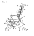
- the chair 1 comprises a leg unit 1; a seat 2 supported by the leg unit 1; a backrest support frame 3 pivotally mounted at the lower front end to the leg unit 1; a backrest 6 comprising a mesh-like backrest plate 4 and a cushion 5; and a pair of rhombus-like armrests 7 at the lower part of the backrest support frame 3.
- the leg unit 2 comprises a pair of side legs 9,9 each comprising a front leg portion 9a having a caster 8 at the front end and a rear leg portion 9b having a caster 8 at the rear end, the rear leg portion being longer than the front leg portion 9a; and a stretcher 10 between the side legs 9 and 9 at the upper ends.
- the reason that the rear leg portion 9b is longer than the front leg portion 9a is to keep the chair more stable when the backrest 6 is tilted rearward.
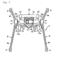
- the distance between the front leg portions 9a and 9a of the side legs 9 gradually becomes greater forward, and the distance between the rear leg portions 9b and 9b gradually becomes greater rearward thereby making the leg unit 1 more stable.
- a shorter shaft 11 is integrally formed with the upper end of each of the side legs 9.
- a mounting piece 12 projects downward from the inner side surface of the front end of the rear leg portion 9b in Fig. 3 .
- a head of the bolt 13 disposed in the shorter shaft 11 is covered with a circular cap 14 (not shown in Fig. 5 ) mounted in a groove of the side of the shorter shaft 11.
- a support base 15 for supporting the seat 2 is fixed at the rear end to a projection 10c in the middle of the lateral rod 10b of the stretcher 10 with a bolt 16 so that the front end of the support base 15 projects ahead of the lateral rod 10b.
- the vertical portion 10a of the U-shaped stretcher 10 is fixed at the upper end to the top of the side leg 9, and the lateral rod 10b is fixed to the mounting piece 12 of the rear leg portion 9b, such that the upper end of the support base 15 is slightly higher than the top of the side leg 9.
- the backrest support frame 3 stands at the rear end of the seat; and comprises a pair of side frames 17,17 each having an arm 17a at the lower end which slants diagonally backward and an arc-like top frame 18 connecting the upper ends of the side frames 17,17 to each other.
- the distance between the right and left side frames 17 and 17 is shorter than that that between the right and left rear leg portions 9b and 9b of the pair of side legs 9.
- the arms 17a,17a do not engage with the rear leg portions 9b and 9b.
- each of the arms 17a there is formed a rounded portion 17b nearly coaxial with the shorter shaft 11 at the top of the side leg 9.
- the rounded portion 17b is pivotally coupled to a torsion shaft (not shown) such as a known rubber torsion unit of a reclining mechanism in the support base 15 while it is forced counterclockwise anytime.
- a torsion shaft such as a known rubber torsion unit of a reclining mechanism in the support base 15 while it is forced counterclockwise anytime.
- a pair of seat-support links 20,20 is pivotally mounted to a cylindrical support 19 projecting transversely from the support base 15, with a pivot shaft 21.
- Seat-support pieces 22,22 project upward from the front end of the arm 17a of the backrest support frame 3.
- a rectangular armrest mounting portion 23 projects with the seat-support piece 22 on the upper surface of the arm 17a.
- a seat frame 24 mounted on the lower surface of the seat 2 is pivotally mounted at the front end to the upper end of the seat support link 20, and is pivotally mounted at the rear end to the upper end of the seat-support piece 22 with a pivot shaft 26 as shown in Fig. 3 .
- the front part of the seat 2 is supported by the support base 15 coupled with the leg unit 1 with the seat support link 20, and the middle part of the seat 2 by the arms 17a of the backrest support frame 3 with the seat support piece 22.
- Fig. 4 when the backrest support frame 3 is tilted rearward with the backrest 6, the seat 2 is tilted rearward together.
- the rear part of the front leg portion 9a and the front part of the rear leg portion 9b are positioned inside the side edges of the seat 2, so that the side legs 9 of the leg unit 1 do not project sideward as shown in Fig. 2 .
- the backrest support frame 3 is pivotally mounted at the front lower end to the support base 15 coupled to the leg unit 1 increasing a rotation radius from the pivot to the upper ends of the backrest support frame 3 and backrest 6.
- the backrest 6 can be tilted more extensively at a small rotation angle, and a rearward projection can be minimized.
- the chair can be inclined rearward extensively without increasing heights of the leg unit 1 and seat 2 thereby providing a low and backward-tilting chair with sitting comfort.
- the front ends of the backrest support frame 3 and seat 2 are pivotally mounted to the support base 15 on the lateral rod 10b of the stretcher 10.
- the support base 15 is as high as the top of the side leg 9 reducing one's sitting height and improving sitting comfort.
- the arm 17a of the backrest support frame 3 is relatively long and tilted upward and rearward below the seat 2.
- the arm 17a is pivotally mounted at a position which is almost as high as the top of the side leg 9 increasing a rotation angle of the arm 17a and avoiding the rear end of the arm 17a from getting in touch with the floor.
- the distances between the front leg portions 9a and 9a and between the rear leg portions 9b and 9b become greater forward and rearward respectively, and the rear leg portions 9b are longer than the front leg portions 9a thereby keeping the chair more stable when the backrest 6 is tilted rearward. Since the distance between the front leg portions 9a and 9a becomes greater forward, a lower limb of the sitting person is unlikely to hit the front leg portion 9a.
- the arm 17a of the backrest support frame 3 is pivotally mounted to the support base 15, but may be pivotally mounted to the tops of side legs or inner side surfaces of the short shafts.
- the seat 2 is tilted together with the backrest support frame 3, but the seat 2 may be fixed to the top of a leg unit including a support base.
Landscapes
- Health & Medical Sciences (AREA)
- Dentistry (AREA)
- General Health & Medical Sciences (AREA)
- Chairs For Special Purposes, Such As Reclining Chairs (AREA)
- Chairs Characterized By Structure (AREA)
- Chair Legs, Seat Parts, And Backrests (AREA)
Applications Claiming Priority (4)
| Application Number | Priority Date | Filing Date | Title |
|---|---|---|---|
| JP2006162632A JP4926551B2 (ja) | 2006-06-12 | 2006-06-12 | 椅子 |
| JP2006162631A JP4964506B2 (ja) | 2006-06-12 | 2006-06-12 | 椅子 |
| JP2006163383A JP4964507B2 (ja) | 2006-06-13 | 2006-06-13 | 椅子 |
| PCT/JP2007/061739 WO2007145170A1 (fr) | 2006-06-12 | 2007-06-11 | Siège |
Publications (2)
| Publication Number | Publication Date |
|---|---|
| EP2033541A1 true EP2033541A1 (fr) | 2009-03-11 |
| EP2033541A4 EP2033541A4 (fr) | 2014-01-22 |
Family
ID=38831684
Family Applications (1)
| Application Number | Title | Priority Date | Filing Date |
|---|---|---|---|
| EP07745028.6A Withdrawn EP2033541A4 (fr) | 2006-06-12 | 2007-06-11 | Siège |
Country Status (6)
| Country | Link |
|---|---|
| US (1) | US20090195043A1 (fr) |
| EP (1) | EP2033541A4 (fr) |
| JP (1) | JP4964506B2 (fr) |
| CN (1) | CN101500455B (fr) |
| CA (1) | CA2655276C (fr) |
| WO (1) | WO2007145170A1 (fr) |
Families Citing this family (3)
| Publication number | Priority date | Publication date | Assignee | Title |
|---|---|---|---|---|
| JP6494088B2 (ja) * | 2015-01-16 | 2019-04-03 | 株式会社オカムラ | 反力機構、及び、それを用いる椅子 |
| US11672343B2 (en) | 2021-07-14 | 2023-06-13 | Anthro Form, Llc | 4-star base for a chair |
| USD1119345S1 (en) | 2022-06-10 | 2026-03-24 | Anthro Form, Llc | Chair |
Family Cites Families (21)
| Publication number | Priority date | Publication date | Assignee | Title |
|---|---|---|---|---|
| DE1117835B (de) * | 1956-07-23 | 1961-11-23 | William H Reinholz | Bodenanker fuer Kinderlaufstuehle |
| US4303219A (en) * | 1979-12-14 | 1981-12-01 | Carrick Virgil P | Swivel-rocker base |
| JPS59114051U (ja) * | 1983-01-24 | 1984-08-01 | 株式会社岡村製作所 | 座と背もたれが連動して傾動する椅子 |
| IT1161498B (it) * | 1983-07-12 | 1987-03-18 | Castelli Spa | Sedia |
| US5967609A (en) * | 1996-11-18 | 1999-10-19 | Hwe, Inc. | Reclining chair with guide rail system |
| JPH10276853A (ja) * | 1997-04-02 | 1998-10-20 | Chuo Katan Kogyo Kk | スタッキング椅子 |
| DE19754829A1 (de) * | 1997-12-10 | 1999-07-08 | Wilkhahn Wilkening & Hahne | Sitzmöbel |
| US5868468A (en) * | 1998-04-24 | 1999-02-09 | Wang; Chin-Chen | Chair with adjustable inclination |
| US6030037A (en) * | 1998-05-15 | 2000-02-29 | Steelcase Inc. | Horizontally nestable chair |
| US6412869B1 (en) * | 1999-05-27 | 2002-07-02 | Steelcase Development Corporation | Nestable synchrotilt chair |
| JP2002282077A (ja) | 2001-03-23 | 2002-10-02 | Okamura Corp | 椅 子 |
| US6609755B2 (en) * | 2001-06-15 | 2003-08-26 | Hon Technology Inc. | Ergonomic chair |
| US6595584B1 (en) * | 2002-01-16 | 2003-07-22 | John W. Caldwell | Seating for individuals and for groups of individuals with various degrees of accommodation and distraction |
| JP4154934B2 (ja) | 2002-06-17 | 2008-09-24 | 松下電工株式会社 | マッサージ椅子 |
| JP2004033449A (ja) | 2002-07-03 | 2004-02-05 | Kokuyo Co Ltd | 椅子のレバー取付構造 |
| JP2004057572A (ja) * | 2002-07-30 | 2004-02-26 | Itoki Crebio Corp | 連結可能な椅子 |
| USD512846S1 (en) * | 2003-05-19 | 2005-12-20 | Hni Technologies Inc. | Mobile guest chair with arms |
| JP4589621B2 (ja) | 2003-12-19 | 2010-12-01 | 株式会社岡村製作所 | 椅子 |
| USD542549S1 (en) * | 2005-11-10 | 2007-05-15 | Okamura Corporation | Chair |
| USD543042S1 (en) * | 2005-11-10 | 2007-05-22 | Okamura Corporation | Chair |
| USD543040S1 (en) * | 2005-11-10 | 2007-05-22 | Okamura Corporation | Chair |
-
2006
- 2006-06-12 JP JP2006162631A patent/JP4964506B2/ja not_active Expired - Fee Related
-
2007
- 2007-06-11 US US12/304,523 patent/US20090195043A1/en not_active Abandoned
- 2007-06-11 CA CA2655276A patent/CA2655276C/fr not_active Expired - Fee Related
- 2007-06-11 CN CN2007800300540A patent/CN101500455B/zh not_active Expired - Fee Related
- 2007-06-11 EP EP07745028.6A patent/EP2033541A4/fr not_active Withdrawn
- 2007-06-11 WO PCT/JP2007/061739 patent/WO2007145170A1/fr not_active Ceased
Also Published As
| Publication number | Publication date |
|---|---|
| WO2007145170A1 (fr) | 2007-12-21 |
| EP2033541A4 (fr) | 2014-01-22 |
| CA2655276C (fr) | 2013-01-22 |
| JP4964506B2 (ja) | 2012-07-04 |
| CA2655276A1 (fr) | 2007-12-21 |
| CN101500455B (zh) | 2013-05-08 |
| JP2007330337A (ja) | 2007-12-27 |
| CN101500455A (zh) | 2009-08-05 |
| US20090195043A1 (en) | 2009-08-06 |
Similar Documents
| Publication | Publication Date | Title |
|---|---|---|
| US6923503B2 (en) | Chair with movable seat and backrest | |
| KR20190044580A (ko) | 의자 구조 및 의자 | |
| JPH1033294A (ja) | 可撓性を有する積重ね可能な椅子 | |
| CN105592752A (zh) | 座椅 | |
| JPH09164036A (ja) | 座部が背もたれ部の位置に適した適当な位置を占めることを保証する装置及びこの装置を含む椅子 | |
| CA2655276C (fr) | Siege dote d'une base d'appui | |
| CN111067293A (zh) | 一种带搁脚板的椅子 | |
| JP3803642B2 (ja) | 収納式椅子 | |
| CN212938946U (zh) | 座椅的底盘机构及座椅 | |
| CN111616541A (zh) | 一种椅架 | |
| JP7854702B2 (ja) | 椅子 | |
| CN211933364U (zh) | 一种带搁脚板的椅子 | |
| JP4926551B2 (ja) | 椅子 | |
| CN223731644U (zh) | 可调节座椅角度的轮椅 | |
| JPH0221965Y2 (fr) | ||
| JP4964507B2 (ja) | 椅子 | |
| JPH0111088Y2 (fr) | ||
| CN213464432U (zh) | 椅架 | |
| JPH0357164Y2 (fr) | ||
| JP2001314281A (ja) | ソファー | |
| CN111096594A (zh) | 一种椅子及其搁脚板组件 | |
| CN219460699U (zh) | 一种灵活调整的扶手 | |
| JP3225237U (ja) | チェアー | |
| JP5497075B2 (ja) | 椅子 | |
| JP4652760B2 (ja) | リクライニング椅子 |
Legal Events
| Date | Code | Title | Description |
|---|---|---|---|
| PUAI | Public reference made under article 153(3) epc to a published international application that has entered the european phase |
Free format text: ORIGINAL CODE: 0009012 |
|
| 17P | Request for examination filed |
Effective date: 20090109 |
|
| AK | Designated contracting states |
Kind code of ref document: A1 Designated state(s): AT BE BG CH CY CZ DE DK EE ES FI FR GB GR HU IE IS IT LI LT LU LV MC MT NL PL PT RO SE SI SK TR |
|
| AX | Request for extension of the european patent |
Extension state: AL BA HR MK RS |
|
| DAX | Request for extension of the european patent (deleted) | ||
| A4 | Supplementary search report drawn up and despatched |
Effective date: 20140107 |
|
| RIC1 | Information provided on ipc code assigned before grant |
Ipc: A47C 7/44 20060101ALI20131219BHEP Ipc: A47C 1/024 20060101AFI20131219BHEP Ipc: A47C 7/00 20060101ALI20131219BHEP Ipc: A47C 1/032 20060101ALI20131219BHEP |
|
| STAA | Information on the status of an ep patent application or granted ep patent |
Free format text: STATUS: THE APPLICATION IS DEEMED TO BE WITHDRAWN |
|
| 18D | Application deemed to be withdrawn |
Effective date: 20140805 |