EP2033670A1 - Moyen de fixation pour objectifs médicaux, en particulier pour la fixation d'une géométrie de référence pour des opérations assistées par navigation, sur un corps, notamment sur un os - Google Patents
Moyen de fixation pour objectifs médicaux, en particulier pour la fixation d'une géométrie de référence pour des opérations assistées par navigation, sur un corps, notamment sur un os Download PDFInfo
- Publication number
- EP2033670A1 EP2033670A1 EP07112624A EP07112624A EP2033670A1 EP 2033670 A1 EP2033670 A1 EP 2033670A1 EP 07112624 A EP07112624 A EP 07112624A EP 07112624 A EP07112624 A EP 07112624A EP 2033670 A1 EP2033670 A1 EP 2033670A1
- Authority
- EP
- European Patent Office
- Prior art keywords
- carbon fiber
- fiber reinforced
- substituted
- unsubstituted
- fastening means
- Prior art date
- Legal status (The legal status is an assumption and is not a legal conclusion. Google has not performed a legal analysis and makes no representation as to the accuracy of the status listed.)
- Granted
Links
Images




Classifications
-
- A—HUMAN NECESSITIES
- A61—MEDICAL OR VETERINARY SCIENCE; HYGIENE
- A61L—METHODS OR APPARATUS FOR STERILISING MATERIALS OR OBJECTS IN GENERAL; DISINFECTION, STERILISATION OR DEODORISATION OF AIR; CHEMICAL ASPECTS OF BANDAGES, DRESSINGS, ABSORBENT PADS OR SURGICAL ARTICLES; MATERIALS FOR BANDAGES, DRESSINGS, ABSORBENT PADS OR SURGICAL ARTICLES
- A61L31/00—Materials for other surgical articles, e.g. stents, stent-grafts, shunts, surgical drapes, guide wires, materials for adhesion prevention, occluding devices, surgical gloves, tissue fixation devices
- A61L31/12—Composite materials, i.e. containing one material dispersed in a matrix of the same or different material
- A61L31/125—Composite materials, i.e. containing one material dispersed in a matrix of the same or different material having a macromolecular matrix
- A61L31/126—Composite materials, i.e. containing one material dispersed in a matrix of the same or different material having a macromolecular matrix containing carbon fillers
-
- A—HUMAN NECESSITIES
- A61—MEDICAL OR VETERINARY SCIENCE; HYGIENE
- A61B—DIAGNOSIS; SURGERY; IDENTIFICATION
- A61B90/00—Instruments, implements or accessories specially adapted for surgery or diagnosis and not covered by any of the groups A61B1/00 - A61B50/00, e.g. for luxation treatment or for protecting wound edges
- A61B90/39—Markers, e.g. radio-opaque or breast lesions markers
-
- A—HUMAN NECESSITIES
- A61—MEDICAL OR VETERINARY SCIENCE; HYGIENE
- A61B—DIAGNOSIS; SURGERY; IDENTIFICATION
- A61B17/00—Surgical instruments, devices or methods
- A61B2017/00831—Material properties
- A61B2017/00902—Material properties transparent or translucent
- A61B2017/00915—Material properties transparent or translucent for radioactive radiation
-
- A—HUMAN NECESSITIES
- A61—MEDICAL OR VETERINARY SCIENCE; HYGIENE
- A61B—DIAGNOSIS; SURGERY; IDENTIFICATION
- A61B17/00—Surgical instruments, devices or methods
- A61B2017/00831—Material properties
- A61B2017/00902—Material properties transparent or translucent
- A61B2017/00915—Material properties transparent or translucent for radioactive radiation
- A61B2017/0092—Material properties transparent or translucent for radioactive radiation for X-rays
-
- A—HUMAN NECESSITIES
- A61—MEDICAL OR VETERINARY SCIENCE; HYGIENE
- A61B—DIAGNOSIS; SURGERY; IDENTIFICATION
- A61B90/00—Instruments, implements or accessories specially adapted for surgery or diagnosis and not covered by any of the groups A61B1/00 - A61B50/00, e.g. for luxation treatment or for protecting wound edges
- A61B90/39—Markers, e.g. radio-opaque or breast lesions markers
- A61B2090/3983—Reference marker arrangements for use with image guided surgery
Definitions
- the present invention relates to a fastener for medical purposes, in particular for attaching a reference geometry for navigation-supported operations on a body, in particular on a bone.
- the fastener of the invention is at least partially made of a particular material that provides advantages in terms of X-ray transparency and 3D x-ray image artifacts.
- it is designed so that it can be attached by means of a specific mechanism to a body, which offers advantages in terms of possible tensions and bends.
- Fasteners for medical purposes in particular for fastening a reference geometry for navigation-assisted operations on a body, in particular on a bone, are already known from the prior art.
- These are structurally differently configured fastening means, such as clamps or tongs, which are provided with pointed portions such as spikes, which are bored in the attachment to a body or bone in this.
- Other known fastening means are substantially rod-shaped fastening means are screwed into the screws so that pointed portions can penetrate into the body or bone for fixation.
- fixing means in the form of plates, which are fastened by means of a plurality of screws to a body, in particular to a bone.
- markers which are used in navigation-supported operations.
- the markers may be active markers which themselves emit radiation detected by a camera in the operating room, or they may be passive markers which only reflect radiation, the reflected radiation then being detected by a camera system in the operating room becomes.
- a treatment device to be navigated such as a surgical instrument, for example, is likewise provided with a reference geometry with corresponding markers, and if the marker device of the treatment device to be navigated is detected simultaneously with the marker device fixed on the body or bone, the determined relative position between the marker can be determined Marker device on the treatment device to be navigated on the one hand and the marker device, which is fixed to the body, on the other hand, be inferred to the position of the treatment device to be navigated.
- fasteners Another requirement of generic fasteners is their sterilizability. The fasteners are in fact reused several times.
- the imaging methods may, for example, be different types of X-ray images (2D X-ray, 3D X-ray or 3D computed tomography).
- X-ray images 2D X-ray, 3D X-ray or 3D computed tomography.
- artifact formation is different in two-dimensional X-ray images than in three-dimensional X-ray images, which are composed and reconstructed from various two-dimensional images.
- materials that are X-ray transparent, such as plastics or certain ceramics good two-dimensional radiographs (fluoroscopic images) can generally be obtained.
- the medical fastener according to the invention in particular for attaching a reference geometry for navigation-assisted operations, to a body, in particular to a bone, is characterized in that at least part of the fastener is made of a carbon fiber reinforced unsubstituted, carbon fiber reinforced monosubstituted or carbon fiber reinforced multiply substituted polyether compound, especially consists of a carbon fiber reinforced, unsubstituted, carbon fiber reinforced monosubstituted or carbon fiber reinforced multi-substituted aromatic polyether compound.
- the carbon fiber reinforced unsubstituted carbon fiber reinforced singly substituted or carbon fiber reinforced multi-substituted aromatic polyether compound is preferably carbon fiber reinforced unsubstituted carbon fiber reinforced singly substituted or carbon fiber reinforced multi-substituted polyaryletherketones, especially poly (etheretherketone) s (PEEK), poly (etherketone) s (PEK) or poly (ether ketone ketone) s (PEKK).
- PEEK poly (etherketone) s
- PEK poly (etherketone) s
- PEKK poly (ether ketone ketone) s
- FIG. 1a illustrates. Based on the individual benzene rings, the connection to the chain takes place in each case in the 1,4-position, that is to say in the para position. The connection of the individual benzene rings within the chain in the para position gives the poly (ether ketone) s its relatively high strength.
- PEEK is understood to mean a polymer composed of multiple units, each unit consisting of three benzene rings, each linked together by a first ether bridge, a second ether bridge and a keto bridge. This is in FIG. 1a (Center) illustrates. This classification can be continued for so-called PEKK, ie poly (ether ketone ketone).
- FIG. 1a (below).
- the number of base units linked in the manner described is in FIG. 1 a labeled n.
- the carbon fiber reinforced unsubstituted, carbon fiber reinforced singly substituted or carbon fiber reinforced multiply substituted aromatic polyether compound is a polyetherimide (PEI), ie a polymer whose backbone is composed of aromatic rings linked via ether and imide groups , Exemplary is the structure of such a polyetherimide in FIG. 1b shown. The number of base units linked in the manner described is in FIG. 1b denoted by n.
- PEI polyetherimide
- the benzene rings may be monosubstituted or polysubstituted.
- the substitution can take place in the meta and / or ortho position.
- the substitution on a benzene ring can be identical on all benzene rings of the entire polymer, but it can also be different.
- C 1 -C 8 -alkyls that is methyl, ethyl, propyl, butyl, pentyl, hexyl, heptyl, and / or octyl groups.
- Each of the abovementioned C 1 -C 8 -alkyls may in particular be straight or branched.
- iso-propyl, sec-butyl, tert-butyl substituents, as well as any isomers of the C5-C8 alkyl substituents are possible.
- the substituents may be C 2 -C 8 alkenyls; that is, straight or branched ethenyl, propenyl, butenyl, pentenyl, hexenyl, heptenyl and / or octenyl groups.
- the substituents can be straight or branched C 2 -C 8 -alkynyl groups; that is, ethynyl, propynyl, butynyl, pentynyl, hexynyl, heptynyl, and / or octynyl groups, each straight or branched.
- the substituents may be C 1 -C 8 alkoxyl, that is, methoxy, ethoxy, propoxy, butoxy, pentoxy, hexoxy, heptoxy and / or octoxy groups.
- the substituents may also be cyclic, nonaromatic or aromatic C 4 -C 8 -alkyl substituents, such as, for example, cyclo-butyl, cyclo-pentyl, cyclo-hexyl, cycloheptyl or cyclo-octyl radicals.
- the substituents may be chlorine, iodine and / or bromine.
- All of the abovementioned unsubstituted, mono- or polysubstituted polyether compounds are carbon fiber-reinforced according to the invention.
- carbon fiber reinforcement optionally short fibers, long fibers and / or continuous fibers can be used. As short fibers thereby fibers are understood, which have a length between 0.1 and 1 mm. Long fibers are fibers which have a length between 1 and 50 mm. Continuous fibers should be considered if their length exceeds 50 mm.
- the continuous fibers may have been processed in various ways, for example in the form of rovings, as a fabric or a scrim.
- the type of fiber reinforcement can be described not only by the type of fiber but also by the volume fraction of the fiber which it occupies as a whole in the case of the fastening means according to the invention.
- at least a portion of the carbon fiber reinforced unsubstituted, carbon fiber reinforced, singly substituted or carbon fiber reinforced multi-substituted PEEK, PEK, PEKK or PEI part comprises carbon fiber reinforcement by means of long fibers or continuous fibers.
- the carbon fiber content of the at least one part reinforced by long fibers or continuous fibers is 50 to 65 volume percent, preferably 55 to 60 volume percent (% vol).
- At least a portion of the carbon fiber reinforced unsubstituted, carbon fiber reinforced singly substituted or carbon fiber reinforced multi-substituted PEEK, PEK, PEKK or PEI part comprises carbon fiber reinforcement by short fibers.
- the carbon fiber content of the at least one part, which is reinforced by short fibers between 25 and 35% vol., Preferably at about 30% vol ..
- At least part of the fastener should be made of the materials described above. This can be realized in that the fastening means itself is designed in several parts and one of these parts is constructed from the described materials or consists. It is also possible that the fastening means itself is integrally formed, wherein the single part composed of different materials. This can be achieved for example by a layer structure, wherein a layer consists of the materials described above.
- a fastener according to the invention comprises at least one further part or portion which, unlike other parts of the invention, is made of non-carbon fiber reinforced unsubstituted, non-carbon fiber reinforced singly substituted or non-carbon fiber reinforced multi-substituted PEEK, PEK, PEKK or PEI consists. This may be the case, for example, with parts of the fastener which are subjected to less severe stresses.
- the fastening means is designed in the form of a clamp.
- a clamp while an object is understood, which can fix an object between these two sides of at least two sides, by the application of holding forces. It is possible that the body to be held by the terminal is penetrated, but it is also possible that the body remains intact.
- the clamp is attached to a bone tension balanced.
- a bone tension balanced This is to be understood as follows: If a clamp is attached to a bone, bending forces occur in addition to the normal holding forces. The targeted avoidance of these bending forces within parts, which would negatively affect this type of load, is the basis for the voltage-balanced embodiment.
- parts of the clamp forces act in a symmetrical manner, that is, in the same strength and in a symmetrical manner with respect to the directions of the forces, so that they compensate each other. This is not taken into account in conventional terminals. This can lead to stiffness of the fastening mechanism, mechanical deformations and effects on the accuracies of the reference geometrical separation, or it would mean that the construction would have to be made larger, which would be unacceptable for the intended use.
- the clamp has a clamping region and a carrier region with a transmission section, wherein the clamping region and the transmission section are in contact with one another.
- the clamp area is adapted to secure the clamp to a bone.
- An interaction between the transfer section and the clamping area takes place at a clamping voltage-balanced.
- To the terminal portion of the terminal all those components of the terminal are counted, which are essential for the fixing operation or clamping operation. These are in particular the parts that are set in motion for clamping.
- everything that does not belong to the clamping area belongs to the carrier area of the clamp.
- the part of the carrier area which is in contact with the clamping area is called a transfer section because of the interaction occurring there. Bending forces act on the clamping area during mounting.
- the carrier region further comprises a bearing portion.
- the clamping region has two legs which are each mounted rotatably about an axis, which is respectively guided through the bearing portion.
- the clamp is designed such that the transmission section interacts symmetrically with both legs at the same time and thereby causes a rotation of the legs about their rotation axes of the same magnitude, but in the opposite direction of rotation, so that the clamp can be attached to the bone in a voltage-balanced manner.
- the two axes of rotation are in the same plane in each case the same distance from the end points of the respective leg of the clamping area.
- the bearing portion has a major axis
- the transmission portion is formed in a tapered shape
- the attachment means is configured such that the tapered transmission portion moves along the major axis of the bearing portion, thereby rotating the legs of the clamping portion.
- the tapered transmission portion may, for example, have a wedge shape or be formed in the shape of a truncated cone. Under a wedge shape is understood a three-dimensional shape, which is at least in one dimension from one end Tapered to the other end. This rejuvenation can also be done in two dimensions.
- the main axis is to be understood as the main axis with the lowest moment of inertia, that is, in principle, what is commonly referred to as axis in colloquial usage because it has the greatest longitudinal extent.
- the movement of the wedge-shaped transmission section along the main axis of the bearing section may be a sliding operation. This can be done solely by a translational movement of the wedge-shaped transmission section relative to the legs of the clamping area. But it is also possible that the transmission section is not wedge-shaped, but for example, frusto-conical, with the relative movement then would not have to exhaust in a translational movement, but in addition a rotational movement would be possible.
- the transmission section is wedge-shaped and has a guide for one end of the legs.
- the guide can be the positive mold or the negative mold of a guide, that is to say the legs can engage with their ends, for example, into the guide and be inserted into it, but they can also enclose them from the outside in a suitable manner so as to be guided become.
- the carrier region has an actuating section which, when actuated, sets the transfer section in motion.
- This may be, for example, a screw which moves with a corresponding rotational movement along a screw in the axial direction and on the transmission portion exerts a force which displaces the transmission section, for example in a translational movement and / or a rotational movement.
- a fastening means has at least one indenter, which consists of a silicon nitride ceramic, preferably a ⁇ -silicon nitride ceramic.
- An indentor is understood to mean a wedge or a region which penetrates during fixation into the body on which the fixation is to take place. In the case of bones are in particular so-called pins or spikes, with a Tip are provided and can withstand strong loads.
- several indenters are provided, these are preferably in the case of a terminal as a fastener on both legs of the terminal.
- the silicon nitride ceramic is preferably a ⁇ -silicon nitride ceramic. It is possible for the silicon nitride ceramic or ⁇ -silicon nitride ceramic to be admixed with other ceramics.
- a fastening means with at least one indenter which is attached to the fastening means by means of a captive.
- a captive is a part of the fastener, which prevents indentation in the body on which the fixation was made, for example a bone remain when loosening the fastener. It is also prevented that the indenters, after they have already become loose, although remove, but then fall during the total removal process and get into an open wound and may be there are no longer findable.
- the anti-loss device has a small plate, through which the at least one indentor partially protrudes, wherein the plate clamps a part of the indentor, which does not protrude through the plate, between the fixing device and the platelet.
- This can typically be accomplished by not having the indenters everywhere (the same as the tip) throughout the same diameter. For example, they may widen away from the tip gradually or continuously so that they do not pass completely through the wafer. Preference is given to a gradual widening of the diameter and thereby a possible flat support of the wafer over a part of the indenter.
- the captive is fastened by means of a click fastener to the fastening means. This can be ensured for example by locking small projections. Alternatively, it is also conceivable that the captive is screwed or glued.
- a system comprising a fastener as described above in various embodiments and a reference geometry for navigational support operations.
- This may be attached to the fastening means, or merely be attachable thereto.
- the reference geometry is the marker devices known per se, with active or passive markers, the markers being located in a defined known position relative to one another and being able to be detected by a camera system on the basis of the radiation emitted by them or due to the radiation reflected by them ,
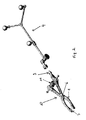
- FIG. 2 shows a clamp 10, which can be equipped with a reference geometry 4, which is commonly made of stainless steel.
- the conventional clamp of the prior art is not radiolucent. It has two clamping jaws or legs 1, which are rotatably mounted about a common axis 6. At one end, the legs 1 are equipped with spikes 7, which can drill into a bone. At the opposite end of the legs a screw connection or screw 11 is provided between the two legs 1. By extending or shortening the distance between the two spike-distal ends of the legs 1, the clamp 10 is opened or closed and tightened.
- the clamp 10 has an interface 9 to which a reference geometry 4 can be attached.
- terminal 10 and reference geometry 4 All components in FIG. 2 are shown (terminal 10 and reference geometry 4) are made of stainless steel and are not radiolucent. The situation is different with a clamp according to the invention, which consists at least partially of a carbon fiber reinforced unsubstituted, carbon fiber reinforced single-substituted or carbon fiber reinforced multiply substituted polyether compound. All mentioned polyether compound variants are radiolucent.
- FIG. 8 shows the geometry of a fastener according to the invention, which is in the form of a clamp 10.
- the clamp 10 is attached by means of two jaws 1 on the spinous process of a vertebral body 12a.
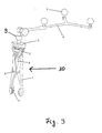
- FIG. 9 shows the clamp 10 with a reference geometry 4 attached thereto via an interface 9 in detail.
- the reference geometry 4 was in the case all test shots made of stainless steel. But it is also conceivable that a radiolucent material such as plastic or a specific ceramic is used for the reference geometry 4.
- the clamp in FIG. 9 has two opposing legs 1 in the form of jaws. At the ends at which contact with the bone is to be produced, the legs 1 each have spikes 7. These are made of silicon nitride ceramic (SNI 750, see data sheet 4 in the appendix).
- the clamp 10 further comprises a main rod 8, which includes two axes of rotation 6, in which the legs 1 are respectively stored.
- a wedge piece 2 which serves as a transfer section, is in contact with a rotary wheel 3 which has a screw connection to the main bar 8.
- the wedge piece 2 moves downward, which is why the jaws 1 close.
- the clamping force is transmitted symmetrically to the wedge piece 2, for this reason, no critical bending force occurs on the main rod 8, which could lead to a shift of the reference.
- the legs 1 have elements that engage in corresponding guide slots on the wedge piece 2 and are connected in this way with the wedge piece 2, and ensure that the jaws open automatically when the rotary knob 3 is rotated in the opposite direction.
- the rotary wheel 3 can be easily removed from the wedge piece 2 for cleaning and sterilization purposes.
- An interface 9 ensures that the reference geometry 4 can be switched on and off.
- the reference geometry 4 has at least three markers 5, which are located at a known, defined distance from each other.
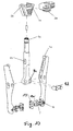
- the terminal 10 is shown in an exploded view in greater detail.
- the main rod 8 has in the upper area (top and bottom, respectively relative to the position in the figure) a cylindrical portion 8a, which includes the interface for the reference geometry.
- a recess 8b which is formed in the present case oval-shaped. Hook 1a of the legs 1 can engage in this recess 8b.
- the main rod 8 has two openings 8c, can be recorded in the axes 8d and simultaneously performed by the legs 1, so that the axes of rotation for both legs 1 can be formed.
- a recess 2b which serves as a guide for the legs 1, which engage by means of the prongs 1a in the guide 2b.
- the rotary wheel 3 is fixed to the wedge piece in that a collar 3a is hineinschiebbar in a correspondingly executed recess 2a of the wedge piece 2.
- the rotary wheel 3, which serves as an actuating piece, can be screwed onto the wedge piece with the main rod 8. If the rotary knob 3 is actuated, that is rotated, is moved or pushed down by the contact to the wedge piece 2 along the main bar 8, and the legs 1 are spread.
- the hook 1a of the legs 1 in the guide 2b of the wedge piece 2 in the wedge piece 2 slip upward, that is, in a region which is widened.
- the wedge piece 2 is mirror-symmetrical with respect to an imaginary axis A. For this reason, the legs 1 and the hook 1a are moved symmetrically. The force exerted by the wedge piece 2 on the legs 1 force is therefore also symmetrical, which is why no critical bending forces on the main rod 8 occur.
- spikes 7 In the terminal area of the terminal 1 several spikes 7 can be seen. These are pressed or glued into the jaws 1. It can be seen that the spikes 7 have a slight thickening at the end opposite to their tip, that is to say the diameter of the spikes (apart from the tip) varies. A wafer 13 provided with holes is now slid over the spikes 7 with only the smaller diameter portions of the spikes fitting through the holes of the wafer 13. The thickened region of the spikes 7 is clamped between the plate 13 and the clamping jaw 1. The plate 13 thus serves as captive. It can be attached to the clamp by means of a click fastener 1b.
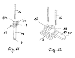
- FIGS. 11 and 12 two further fastening means are shown, which are not formed in the form of a clamp. Instead, in FIG. 11 illustrates a fastener with a screw 16, in FIG. 12 a fastener with two screws 16 is shown.
- the fasteners shown are known in terms of their geometries, but they are in the present case at least partially made of carbon fiber reinforced unsubstituted, carbon fiber reinforced singly substituted or carbon fiber reinforced multi-substituted PEEK. In this case, as in the general part of the description of the invention described a variety of fiber types and carbon fiber contents in volume percent can be used.
- the fastening means has a main part 14 to which a reference geometry can be attached by means of an interface 15.
- the main piece 14 is attached via a bone screw 16, which is screwed into the bone.
- a locking ring 17a is pressed by means of a clamping mechanism 17 against the screw 16, whereby it comes to a fixation.
- the wheel 3 is rotated and a force is exerted on the main body 14. This pushes the spikes 7 into the bone structure.
- the spikes 7 can be made of either plastic or ceramic materials.
- FIG. 12 When fixing in FIG. 12 two bone screws 16 are used, which are attached to the bone structure at a certain distance from each other.
- a drilling template can improve this process.
- the main piece 20 is inserted with the openings 18 on two bone screws 16, which are screwed into the bone.
- the main piece 20 has an interface to which a reference geometry can be attached.
- the wheel 3 moves a wedge-shaped portion 19 inside the main piece 20 whereby the main piece 20 is firmly clamped with the two screws 16.
- a reference geometry can be attached to an interface 15 of the main piece 20.
- fastening means in particular clamps according to the prior art, which are preferably made of titanium or stainless steel, from a different material, without making further adjustments of the fastening means.
- FIG. 2 it is not possible in the FIG. 2 instead of stainless steel made of non-carbon fiber reinforced PEEK - regardless of substitution.
- the non-carbon fiber reinforced PEEK clamp would have to have a size larger by a factor of 2 to 3 than that of the stainless steel clamp heretofore used in the prior art. Otherwise, the necessary strength of the fastener would not be achieved.
- such an increase in size for a fastener used in navigation-assisted operations is unacceptable because of this freedom of movement and view of the surgeon would be too much disabled and a possible minimally invasive application would no longer exist.
- the main bar 8 and the wedge 3 were made of carbon fiber reinforced unsubstituted PEEK, the reinforcement being made by short fibers and the carbon fiber content being about 30% by volume (see data sheet 2 attached).
- the plate 13 and the rotary wheel 3 consisted of non-carbon fiber reinforced unsubstituted PEEK (see data sheet 3 in the appendix).
- the spikes 7 were made of silicon nitride ceramic (see data sheet 4 in the appendix). That the prototype fastener in the form of a clamp is made of different PEEK materials is possible for the following reasons: The forces acting on the fastener differ with respect to the individual components of the fastener.
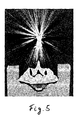
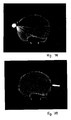
- FIGS. 3a and 3b show individual X-ray sections from a reconstructed 3D X-ray model, which was taken with a computer tomograph. In both cases, a section was taken through a specific vertebra of the spine with a conventional stainless steel clamp fixed to a vertebral body. It is in the FIGS. 3a and 3b to recognize a strong artifact formation. The image is superimposed by strong star-shaped lines in black and white, so that the white vertebrae in the image center are barely recognizable. The images are practically unsuitable for navigational operations, as relevant bone structures on the vertebral body, in which by means of navigation support, for example, screws must be introduced, are no longer recognized.
- FIGS. 4a and 4b show for comparison two different 2D sections through a vertebral body from a reconstructed 3D X-ray model, which was taken with a computer tomograph, using a radiolucent clamp according to the invention made of carbon fiber reinforced PEEK was used.
- the clamp made of carbon fiber reinforced PEEK was equipped with silicon nitride ceramic spikes (SNI 750 according to data sheet 4).
- the silicon nitride ceramic spikes withstand relatively high mechanical loads.
- the light artifacts in the FIGS. 5a and 5b can be seen, resulting from the use of Silizimnnitrid ceramic pins. Nevertheless, it should be noted that these artifacts are so weak in their expression that they do not affect the image quality appreciably negative.
- FIG. 5 a sectional view is shown by a vertebral body from a reconstructed 3D x-ray model, which was taken with a computed tomography, using a clamp made of carbon fiber reinforced PEEK according to the invention was attached to a conventional reference geometry consisting of stainless steel. This is located at a certain distance from the vertebral body, on which the clamp is fixed. Although the artifacts caused by the use of the known stainless steel reference geometry are strong, they are at some distance from the vertebral body of interest. It should be noted that this distance is large enough, so that even when using reference geometries of the prior art stainless steel in combination with the inventive clamp of carbon fiber reinforced PEEK good reconstructed 2D X-ray section recordings can be obtained.
- FIG. 6a and 6b show 3D reconstructions, which were taken with a computer tomograph, wherein FIG. 6a a dorsal 3D reconstruction and FIG. 6b shows a lateral 3D reconstruction.
- a clamp made of stainless steel was mounted in the left area, while the prototype according to the invention was mounted in the right area. It can be seen that much stronger artifacts can be seen on the left side of the stainless steel clamp, and that even relevant areas of the spinal column, such as spinous processes, are completely absent, whereas the right contour shows the complete contour of the clamp and completely reconstructs the underlying area of the spine are. This is especially true for the dorsal 3D reconstruction.
- FIGS. 7a and 7b show the different artifact behavior when using a titanium pin and the use of a silicon nitride ceramic pin in a 3D reconstructed X-ray slice.
- rod-shaped test specimens of the materials mentioned were used.
- strong artifacts occur, while when using the silicon nitride ceramic pins only weak and directed artifacts occur.
- the use of the described carbon-fiber-reinforced PEEK materials resulted in a high mechanical strength of the fastening means ensures and achieves the required degree of miniaturization of the fastener, in particular the clamp, whereby a minimally invasive application is possible.
Landscapes
- Health & Medical Sciences (AREA)
- Life Sciences & Earth Sciences (AREA)
- Surgery (AREA)
- Public Health (AREA)
- Heart & Thoracic Surgery (AREA)
- Engineering & Computer Science (AREA)
- Animal Behavior & Ethology (AREA)
- General Health & Medical Sciences (AREA)
- Veterinary Medicine (AREA)
- Chemical & Material Sciences (AREA)
- Materials Engineering (AREA)
- Composite Materials (AREA)
- Vascular Medicine (AREA)
- Epidemiology (AREA)
- Nuclear Medicine, Radiotherapy & Molecular Imaging (AREA)
- Oral & Maxillofacial Surgery (AREA)
- Pathology (AREA)
- Biomedical Technology (AREA)
- Medical Informatics (AREA)
- Molecular Biology (AREA)
- Surgical Instruments (AREA)
- Chemical Kinetics & Catalysis (AREA)
- Medicinal Chemistry (AREA)
- Polymers & Plastics (AREA)
- Organic Chemistry (AREA)
Priority Applications (2)
| Application Number | Priority Date | Filing Date | Title |
|---|---|---|---|
| EP07112624.7A EP2033670B1 (fr) | 2007-07-17 | 2007-07-17 | Moyen de fixation pour objectifs médicaux, en particulier pour la fixation d'une géométrie de référence pour des opérations assistées par navigation, sur un corps, notamment sur un os |
| US12/175,035 US8939995B2 (en) | 2007-07-17 | 2008-07-17 | Radiolucent reference for computer-assisted surgery |
Applications Claiming Priority (1)
| Application Number | Priority Date | Filing Date | Title |
|---|---|---|---|
| EP07112624.7A EP2033670B1 (fr) | 2007-07-17 | 2007-07-17 | Moyen de fixation pour objectifs médicaux, en particulier pour la fixation d'une géométrie de référence pour des opérations assistées par navigation, sur un corps, notamment sur un os |
Publications (2)
| Publication Number | Publication Date |
|---|---|
| EP2033670A1 true EP2033670A1 (fr) | 2009-03-11 |
| EP2033670B1 EP2033670B1 (fr) | 2015-09-02 |
Family
ID=38777261
Family Applications (1)
| Application Number | Title | Priority Date | Filing Date |
|---|---|---|---|
| EP07112624.7A Active EP2033670B1 (fr) | 2007-07-17 | 2007-07-17 | Moyen de fixation pour objectifs médicaux, en particulier pour la fixation d'une géométrie de référence pour des opérations assistées par navigation, sur un corps, notamment sur un os |
Country Status (2)
| Country | Link |
|---|---|
| US (1) | US8939995B2 (fr) |
| EP (1) | EP2033670B1 (fr) |
Families Citing this family (36)
| Publication number | Priority date | Publication date | Assignee | Title |
|---|---|---|---|---|
| DE102010064389B4 (de) * | 2010-12-30 | 2017-02-02 | Siemens Healthcare Gmbh | Halter zur Aufnahme eines länglichen medizinischen Instruments |
| US9993273B2 (en) | 2013-01-16 | 2018-06-12 | Mako Surgical Corp. | Bone plate and tracking device using a bone plate for attaching to a patient's anatomy |
| US9566120B2 (en) | 2013-01-16 | 2017-02-14 | Stryker Corporation | Navigation systems and methods for indicating and reducing line-of-sight errors |
| US20150282735A1 (en) * | 2014-04-04 | 2015-10-08 | Izi Medical Products,Llc | Reference device for surgical navigation system |
| EP4635432A3 (fr) | 2014-09-24 | 2026-02-18 | 7D Surgical ULC | Structure de support de marqueur de guidage et procédés d'alignement de surface l'utilisant pour pratiquer des interventions chirurgicales par navigation |
| GB2536650A (en) | 2015-03-24 | 2016-09-28 | Augmedics Ltd | Method and system for combining video-based and optic-based augmented reality in a near eye display |
| USD823470S1 (en) * | 2015-07-10 | 2018-07-17 | Brainlab Ag | Reference array |
| EP3247297B1 (fr) | 2016-03-17 | 2018-08-01 | Brainlab AG | Pince à os |
| EP3261572B1 (fr) * | 2016-05-20 | 2018-08-01 | Brainlab AG | Support de fixation de référence de poursuite |
| US10537395B2 (en) | 2016-05-26 | 2020-01-21 | MAKO Surgical Group | Navigation tracker with kinematic connector assembly |
| US11143579B2 (en) | 2016-11-09 | 2021-10-12 | Ohio State Innovation Foundation | Bending apparatus for material testing and micro-CT imaging |
| CN110769775B (zh) * | 2017-05-12 | 2023-08-04 | 网络手术公司 | 自识别手术夹钳、用于与该夹钳一起使用的基准元件及包括这种夹钳和基准元件的套件 |
| WO2019074722A2 (fr) * | 2017-10-10 | 2019-04-18 | Miki Roberto Augusto | Dispositif de serrage orthopedique universel |
| US12521201B2 (en) * | 2017-12-07 | 2026-01-13 | Augmedics Ltd. | Spinous process clamp |
| US12458411B2 (en) | 2017-12-07 | 2025-11-04 | Augmedics Ltd. | Spinous process clamp |
| EP3787543A4 (fr) | 2018-05-02 | 2022-01-19 | Augmedics Ltd. | Enregistrement d'un marqueur fiduciel pour un système de réalité augmentée |
| US11766296B2 (en) | 2018-11-26 | 2023-09-26 | Augmedics Ltd. | Tracking system for image-guided surgery |
| US12059804B2 (en) | 2019-05-22 | 2024-08-13 | Mako Surgical Corp. | Bidirectional kinematic mount |
| US12178666B2 (en) | 2019-07-29 | 2024-12-31 | Augmedics Ltd. | Fiducial marker |
| US11980506B2 (en) | 2019-07-29 | 2024-05-14 | Augmedics Ltd. | Fiducial marker |
| US11382712B2 (en) | 2019-12-22 | 2022-07-12 | Augmedics Ltd. | Mirroring in image guided surgery |
| US11389252B2 (en) | 2020-06-15 | 2022-07-19 | Augmedics Ltd. | Rotating marker for image guided surgery |
| US12502163B2 (en) | 2020-09-09 | 2025-12-23 | Augmedics Ltd. | Universal tool adapter for image-guided surgery |
| US12239385B2 (en) | 2020-09-09 | 2025-03-04 | Augmedics Ltd. | Universal tool adapter |
| EP3988046B1 (fr) * | 2020-10-22 | 2025-07-09 | Cyber Surgery S.L. | Pince à os |
| US12178667B2 (en) | 2021-02-16 | 2024-12-31 | Mako Surgical Corp. | Clamp assembly for fixing a navigation tracker to a portion of bone |
| US12114901B2 (en) * | 2021-05-03 | 2024-10-15 | Warsaw Orthopedic, Inc. | Surgical instrument and method |
| US12150821B2 (en) | 2021-07-29 | 2024-11-26 | Augmedics Ltd. | Rotating marker and adapter for image-guided surgery |
| US12475662B2 (en) | 2021-08-18 | 2025-11-18 | Augmedics Ltd. | Stereoscopic display and digital loupe for augmented-reality near-eye display |
| WO2023203521A1 (fr) | 2022-04-21 | 2023-10-26 | Augmedics Ltd. | Systèmes et procédés de visualisation d'image médicale |
| JP2025531829A (ja) | 2022-09-13 | 2025-09-25 | オーグメディックス リミテッド | 画像誘導医療介入のための拡張現実アイウェア |
| WO2024137963A1 (fr) | 2022-12-21 | 2024-06-27 | Mako Surgical Corp. | Ensemble pince chirurgicale pour fixer un dispositif de suivi de navigation à une partie d'un os |
| US12544115B2 (en) * | 2023-04-17 | 2026-02-10 | MediVis, Inc. | Spinous process clamp |
| USD1117755S1 (en) | 2023-08-18 | 2026-03-10 | Mako Surgical Corp. | Surgical tracker |
| USD1121826S1 (en) * | 2023-08-18 | 2026-04-07 | Stryker European Operations Limited | Surgical tracker |
| USD1120320S1 (en) | 2023-08-18 | 2026-03-24 | Mako Surgical Corp. | Surgical tracker |
Citations (7)
| Publication number | Priority date | Publication date | Assignee | Title |
|---|---|---|---|---|
| EP0171884A1 (fr) * | 1984-06-15 | 1986-02-19 | Imperial Chemical Industries Plc | Dispositifs de prothèses |
| EP1238637A1 (fr) | 2001-03-09 | 2002-09-11 | Co-Ligne AG | Implant longitudinal |
| WO2004075767A1 (fr) | 2003-02-26 | 2004-09-10 | Aesculap Ag & Co. Kg | Dispositif de referenciation de rotule |
| GB2405342A (en) | 2003-08-28 | 2005-03-02 | Biomet Merck Ltd | Bone plate |
| US20050065515A1 (en) * | 2003-09-24 | 2005-03-24 | Tae-Ahn Jahng | Marking and guidance method and system for flexible fixation of a spine |
| EP1718848A1 (fr) | 2003-11-25 | 2006-11-08 | Emmett Limited | Silencieux pour les systemes d'echappement |
| EP1967155A1 (fr) | 2007-03-08 | 2008-09-10 | CAS Innovations AG | Pince médicale, en particulier pince de colonne vertébrale |
Family Cites Families (12)
| Publication number | Priority date | Publication date | Assignee | Title |
|---|---|---|---|---|
| US2249906A (en) * | 1938-09-03 | 1941-07-22 | Ramon Castroviejo | Surgical device |
| US3136040A (en) * | 1961-04-21 | 1964-06-09 | Navigation Computor Corp | Insertion and withdrawal tool |
| US4174715A (en) * | 1977-03-28 | 1979-11-20 | Hasson Harrith M | Multi-pronged laparoscopy forceps |
| US5249574A (en) * | 1991-01-15 | 1993-10-05 | Ventritex, Inc. | Implantation of leads |
| US5637110A (en) * | 1995-01-31 | 1997-06-10 | Stryker Corporation | Electrocautery surgical tool with relatively pivoted tissue engaging jaws |
| DE29610638U1 (de) * | 1996-06-17 | 1997-11-13 | Karl Leibinger Medizintechnik GmbH & Co. KG, 78570 Mühlheim | Fixateur |
| US6226548B1 (en) | 1997-09-24 | 2001-05-01 | Surgical Navigation Technologies, Inc. | Percutaneous registration apparatus and method for use in computer-assisted surgical navigation |
| US6221035B1 (en) * | 1998-11-16 | 2001-04-24 | Richard J. Kana | Automatic ankle clamp |
| US6235027B1 (en) * | 1999-01-21 | 2001-05-22 | Garrett D. Herzon | Thermal cautery surgical forceps |
| US6837892B2 (en) | 2000-07-24 | 2005-01-04 | Mazor Surgical Technologies Ltd. | Miniature bone-mounted surgical robot |
| JP4447015B2 (ja) * | 2003-11-20 | 2010-04-07 | ライト メディカル テクノロジー インコーポレーテッド | 大腿骨内へのガイドワイヤーの配置を案内するためのガイドクランプ |
| WO2006009729A2 (fr) * | 2004-06-18 | 2006-01-26 | Medtronic, Inc. | Procedes et dispositifs d'occlusion d'un appendice auriculaire |
-
2007
- 2007-07-17 EP EP07112624.7A patent/EP2033670B1/fr active Active
-
2008
- 2008-07-17 US US12/175,035 patent/US8939995B2/en active Active
Patent Citations (7)
| Publication number | Priority date | Publication date | Assignee | Title |
|---|---|---|---|---|
| EP0171884A1 (fr) * | 1984-06-15 | 1986-02-19 | Imperial Chemical Industries Plc | Dispositifs de prothèses |
| EP1238637A1 (fr) | 2001-03-09 | 2002-09-11 | Co-Ligne AG | Implant longitudinal |
| WO2004075767A1 (fr) | 2003-02-26 | 2004-09-10 | Aesculap Ag & Co. Kg | Dispositif de referenciation de rotule |
| GB2405342A (en) | 2003-08-28 | 2005-03-02 | Biomet Merck Ltd | Bone plate |
| US20050065515A1 (en) * | 2003-09-24 | 2005-03-24 | Tae-Ahn Jahng | Marking and guidance method and system for flexible fixation of a spine |
| EP1718848A1 (fr) | 2003-11-25 | 2006-11-08 | Emmett Limited | Silencieux pour les systemes d'echappement |
| EP1967155A1 (fr) | 2007-03-08 | 2008-09-10 | CAS Innovations AG | Pince médicale, en particulier pince de colonne vertébrale |
Also Published As
| Publication number | Publication date |
|---|---|
| EP2033670B1 (fr) | 2015-09-02 |
| US8939995B2 (en) | 2015-01-27 |
| US20090024127A1 (en) | 2009-01-22 |
Similar Documents
| Publication | Publication Date | Title |
|---|---|---|
| EP2033670B1 (fr) | Moyen de fixation pour objectifs médicaux, en particulier pour la fixation d'une géométrie de référence pour des opérations assistées par navigation, sur un corps, notamment sur un os | |
| DE69206318T2 (de) | Verriegelbares Verbindungsstück für Verankerungselemente für die Wirbelsäulenosteosynthese. | |
| EP1235520B1 (fr) | Dispositif pour tendre ou comprimer des os ou des parties osseuses | |
| DE60125928T2 (de) | Äusserer einwegfixateur | |
| DE3611319C2 (fr) | ||
| DE69109817T2 (de) | Blockierbares Knochenplattensystem. | |
| EP2323572B1 (fr) | Dispositif de fixation externe de fragments d'os | |
| DE60030233T2 (de) | Anteriorer lumbaler Zwischenwirbelfusionskäfig mit Befestigungsplatte | |
| DE19506564C2 (de) | Knochenklammer | |
| EP0863727B1 (fr) | Dispositif d'osteosynthese | |
| AT389992B (de) | Vorrichtung zur externen fixierung von knochenfragmenten | |
| EP2014251B1 (fr) | Moyen de fixation destiné à la fixation en place d'un corps à des fins médicales en polyphényles et moyen de fixation destiné à la fixation en place d'un corps à des fins médicales en céramique-nitrite de silicium | |
| WO2003034930A1 (fr) | Dispositif de fixation osseuse et vis associee | |
| DE19936570A1 (de) | Isolierhülse für einen tischmontierten Retraktor | |
| DE202004021977U1 (de) | Knochenverankerungsanordnungen | |
| EP2505154A1 (fr) | Implant de colonne vertébrale | |
| EP2618755B1 (fr) | Système de stabilisation de la colonne vertébrale et dispositif chirurgical de raidissement temporaire d'une partie intermédiaire souple d'un élément de liaison du système de stabilisation de la colonne vertébrale | |
| EP1188416B1 (fr) | Vis pédiculaire pour élément de support intervertébral | |
| DE29610638U1 (de) | Fixateur | |
| WO2014029032A1 (fr) | Ressort et dispositif de stabilisation d'os humains ou animaux | |
| DE102007029090A1 (de) | Vorrichtung zur Osteosynthese gelenknaher Knochenfrakturen | |
| WO2024217728A1 (fr) | Pince à os | |
| DE10032126A1 (de) | Instrument zum Einführen eines Verbindungsstabes in Öffnungen der Köpfe von in Wirbelkörper eingeschraubte Pedikelschrauben | |
| DE102023121952A1 (de) | Flexibler Wirbelsäulenkonnetor und Wirbelsäulen-Stabilisierungssystem | |
| DE202024106708U1 (de) | Positionierungshilfe in der Rotationsosteotomie und Montageset zur Positionierung von Kirschner-Drähten |
Legal Events
| Date | Code | Title | Description |
|---|---|---|---|
| PUAI | Public reference made under article 153(3) epc to a published international application that has entered the european phase |
Free format text: ORIGINAL CODE: 0009012 |
|
| 17P | Request for examination filed |
Effective date: 20070717 |
|
| AK | Designated contracting states |
Kind code of ref document: A1 Designated state(s): AT BE BG CH CY CZ DE DK EE ES FI FR GB GR HU IE IS IT LI LT LU LV MC MT NL PL PT RO SE SI SK TR |
|
| AX | Request for extension of the european patent |
Extension state: AL BA HR MK RS |
|
| 17Q | First examination report despatched |
Effective date: 20090617 |
|
| AKX | Designation fees paid |
Designated state(s): DE FR GB |
|
| RAP1 | Party data changed (applicant data changed or rights of an application transferred) |
Owner name: BRAINLAB AG |
|
| REG | Reference to a national code |
Ref country code: DE Ref legal event code: R079 Ref document number: 502007014183 Country of ref document: DE Free format text: PREVIOUS MAIN CLASS: A61L0031120000 Ipc: A61B0019000000 |
|
| GRAP | Despatch of communication of intention to grant a patent |
Free format text: ORIGINAL CODE: EPIDOSNIGR1 |
|
| RIC1 | Information provided on ipc code assigned before grant |
Ipc: A61B 19/00 20060101AFI20150401BHEP Ipc: A61L 31/12 20060101ALI20150401BHEP |
|
| INTG | Intention to grant announced |
Effective date: 20150420 |
|
| GRAS | Grant fee paid |
Free format text: ORIGINAL CODE: EPIDOSNIGR3 |
|
| GRAA | (expected) grant |
Free format text: ORIGINAL CODE: 0009210 |
|
| AK | Designated contracting states |
Kind code of ref document: B1 Designated state(s): DE FR GB |
|
| REG | Reference to a national code |
Ref country code: GB Ref legal event code: FG4D Free format text: NOT ENGLISH |
|
| REG | Reference to a national code |
Ref country code: DE Ref legal event code: R096 Ref document number: 502007014183 Country of ref document: DE |
|
| REG | Reference to a national code |
Ref country code: DE Ref legal event code: R097 Ref document number: 502007014183 Country of ref document: DE |
|
| PLBE | No opposition filed within time limit |
Free format text: ORIGINAL CODE: 0009261 |
|
| STAA | Information on the status of an ep patent application or granted ep patent |
Free format text: STATUS: NO OPPOSITION FILED WITHIN TIME LIMIT |
|
| REG | Reference to a national code |
Ref country code: FR Ref legal event code: PLFP Year of fee payment: 10 |
|
| 26N | No opposition filed |
Effective date: 20160603 |
|
| REG | Reference to a national code |
Ref country code: DE Ref legal event code: R082 Ref document number: 502007014183 Country of ref document: DE Representative=s name: SCHWABE SANDMAIR MARX PATENTANWAELTE RECHTSANW, DE Ref country code: DE Ref legal event code: R081 Ref document number: 502007014183 Country of ref document: DE Owner name: BRAINLAB AG, DE Free format text: FORMER OWNER: BRAINLAB AG, 85622 FELDKIRCHEN, DE Ref country code: DE Ref legal event code: R082 Ref document number: 502007014183 Country of ref document: DE Representative=s name: SSM SANDMAIR PATENTANWAELTE RECHTSANWALT PARTN, DE |
|
| REG | Reference to a national code |
Ref country code: FR Ref legal event code: PLFP Year of fee payment: 11 |
|
| REG | Reference to a national code |
Ref country code: FR Ref legal event code: CA Effective date: 20170706 |
|
| REG | Reference to a national code |
Ref country code: FR Ref legal event code: PLFP Year of fee payment: 12 |
|
| P01 | Opt-out of the competence of the unified patent court (upc) registered |
Effective date: 20230509 |
|
| REG | Reference to a national code |
Ref country code: DE Ref legal event code: R081 Ref document number: 502007014183 Country of ref document: DE Owner name: BRAINLAB SE, DE Free format text: FORMER OWNER: BRAINLAB AG, 81829 MUENCHEN, DE |
|
| PGFP | Annual fee paid to national office [announced via postgrant information from national office to epo] |
Ref country code: DE Payment date: 20250722 Year of fee payment: 19 |
|
| PGFP | Annual fee paid to national office [announced via postgrant information from national office to epo] |
Ref country code: GB Payment date: 20250722 Year of fee payment: 19 |
|
| PGFP | Annual fee paid to national office [announced via postgrant information from national office to epo] |
Ref country code: FR Payment date: 20250724 Year of fee payment: 19 |