EP2033743A2 - Châssis pour un outil motorisé, en particulier un outil électro-manuel - Google Patents
Châssis pour un outil motorisé, en particulier un outil électro-manuel Download PDFInfo
- Publication number
- EP2033743A2 EP2033743A2 EP08015383A EP08015383A EP2033743A2 EP 2033743 A2 EP2033743 A2 EP 2033743A2 EP 08015383 A EP08015383 A EP 08015383A EP 08015383 A EP08015383 A EP 08015383A EP 2033743 A2 EP2033743 A2 EP 2033743A2
- Authority
- EP
- European Patent Office
- Prior art keywords
- drive shaft
- countershaft
- spindle
- tool
- drive
- Prior art date
- Legal status (The legal status is an assumption and is not a legal conclusion. Google has not performed a legal analysis and makes no representation as to the accuracy of the status listed.)
- Granted
Links
Images
Classifications
-
- B—PERFORMING OPERATIONS; TRANSPORTING
- B25—HAND TOOLS; PORTABLE POWER-DRIVEN TOOLS; MANIPULATORS
- B25F—COMBINATION OR MULTI-PURPOSE TOOLS NOT OTHERWISE PROVIDED FOR; DETAILS OR COMPONENTS OF PORTABLE POWER-DRIVEN TOOLS NOT PARTICULARLY RELATED TO THE OPERATIONS PERFORMED AND NOT OTHERWISE PROVIDED FOR
- B25F5/00—Details or components of portable power-driven tools not particularly related to the operations performed and not otherwise provided for
- B25F5/001—Gearings, speed selectors, clutches or the like specially adapted for rotary tools
-
- B—PERFORMING OPERATIONS; TRANSPORTING
- B25—HAND TOOLS; PORTABLE POWER-DRIVEN TOOLS; MANIPULATORS
- B25D—PERCUSSIVE TOOLS
- B25D16/00—Portable percussive machines with superimposed rotation, the rotational movement of the output shaft of a motor being modified to generate axial impacts on the tool bit
- B25D16/003—Clutches specially adapted therefor
-
- B—PERFORMING OPERATIONS; TRANSPORTING
- B25—HAND TOOLS; PORTABLE POWER-DRIVEN TOOLS; MANIPULATORS
- B25D—PERCUSSIVE TOOLS
- B25D2250/00—General details of portable percussive tools; Components used in portable percussive tools
- B25D2250/245—Spatial arrangement of components of the tool relative to each other
-
- F—MECHANICAL ENGINEERING; LIGHTING; HEATING; WEAPONS; BLASTING
- F16—ENGINEERING ELEMENTS AND UNITS; GENERAL MEASURES FOR PRODUCING AND MAINTAINING EFFECTIVE FUNCTIONING OF MACHINES OR INSTALLATIONS; THERMAL INSULATION IN GENERAL
- F16H—GEARING
- F16H1/00—Toothed gearings for conveying rotary motion
- F16H1/02—Toothed gearings for conveying rotary motion without gears having orbital motion
- F16H1/20—Toothed gearings for conveying rotary motion without gears having orbital motion involving more than two intermeshing members
Definitions
- the invention relates to a transmission for a power tool, in particular an electric hand tool device such as a drill according to the preamble of claim 1 and a correspondingly equipped electric hand tool according to the preamble of claim. 9
- these translation stages are realized in that, in addition to the driving anchor pinion offset axially parallel one or more countershafts are mounted with corresponding gear pairings. This is for example from the DE 10 2005 036 731 A1 or even from the EP 1 092 896 A1 . EP 1 147 861 A2 known.
- GB 2 331 268 A is a transmission gear for an angle grinder known, are arranged coaxially with each other in the drive shaft and an output housing in a header output shaft.
- a countershaft is arranged parallel to the input and output shafts.
- Drive and output shaft are each stored separately in the housing. Both the arrangement of drive and output shafts behind each other and an additional bearing between the two, which supports a pinion of the associated output shaft, increase the overall length.
- DE 101 11 748 A1 shows a derailleur, are arranged in the countershaft and percussion drive shaft in a common axial region directly adjacent to each other parallel and a directly meshing, each via a shift sleeve einkuppelbare, driving gear pair lead rotation.
- the DE 197 17 466 B4 shows that the output shaft of the motor via a drive pinion with a ring gear of a trained as a drive sleeve countershaft is engaged, which acts via a planetary gear on another shaft.
- the present invention has the object to provide a transmission for a power tool and an electric hand tool, which is constructed in a compact and weight-oriented.
- Drive shaft and at least one of the countershafts are arranged coaxially with each other. This allows in conjunction with the drive shaft arranged transversely to the spindle a very compact design, in addition to a bearing in the housing is omitted, so that a corresponding weight saving occurs.
- the waves are directly behind each other, where they can be stored on each other or on other components together.
- the bearing of the countershaft preferably takes place on one side on the drive shaft, so that the axis-parallel offset of this shaft to the armature shaft is not required. It should be noted that the storage must accommodate the different speeds of drive shaft and countershaft in operation.
- the bearing is designed so that it takes on the one hand, the axial and radial forces, on the other hand simultaneously compensates the relative speed of the drive shaft and countershaft.
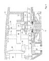
- FIG. 1 shows a view into the gear of a power tool as a section through the housing of the tool.
- Fig. 1 shows a transmission for a power tool, in particular an electric hand tool 10, as it can be used as a drill, drill or chisel hammer. Other uses are conceivable as long as the transmission is constructed as explained below.
- the electric hand tool 10 is driven by a drive motor 11 in the form of an electric motor.
- the drive shaft 12 is the armature shaft of the electric motor.
- the drive shaft may also be the drive shaft of a pneumatic or hydraulic drive unit.
- the tool such as a plug-in tool is driven by a spindle 16.
- the countershafts 13, 14 and 15 and the bearing shaft 27 are provided.
- the drive shaft 12 is coaxial with the countershaft 13, wherein it is also possible to arrange a plurality of countershafts coaxial with the drive shaft 12, provided that storage of the gear parts is ensured by appropriate bearings.
- the coaxial arrangement of the drive shaft and countershaft 13 allows a more compact design, since on the one hand the space that had previously been provided independently of each other for drive shaft and countershaft 13 is now merged.
- Drive shaft 12 and thus also the at least one coaxial with the drive shaft arranged countershaft 13 are arranged transversely to the axial direction of the spindle 16 in the embodiment. Other arrangements e.g. also parallel to the axial direction are conceivable.
- Drive shaft 12, spindle 16 and the countershafts 13, 14, 15 are connected via gear pairings and / or a conical toothing 25, 26 with each other.
- the gear 19 is mounted, which is in operative connection with the gear 20, which is preferably connected to the countershaft 13.
- gear 21 On countershaft 13 is gear 21 which communicates with gear 22 in operative connection, which is mounted on countershaft 15.
- the bearing 28 supports the at least one countershaft 13 on one side of the drive shaft 12.
- the bearing is introduced directly into the gear of the countershaft, which in turn is firmly connected to the countershaft 13.
- Bearing 28 is adapted to receive the axial and radial forces due to different speeds of armature shaft and countershaft.
- the bearing may be directly attached to the countershaft 13 and thus not in the gear 20.
- the gear 20 may be required by a double bearing with the countershaft nor with the drive shaft fixedly connected. If the housing is designed accordingly, the bearing points for the drive shaft 12 and countershaft 13 arranged linearly one behind the other and coaxially with one another can also be provided on the housing.
- Drawing not shown is the entire electric hand tool, which is provided with a tool that is driven to rotate and / or beating. If this power tool is provided with such a transmission, in which the armature shaft 12 and countershaft 13 are arranged coaxially with each other, results in a compact and weight-saving design of the entire device.
Landscapes
- Engineering & Computer Science (AREA)
- Mechanical Engineering (AREA)
- Connection Of Motors, Electrical Generators, Mechanical Devices, And The Like (AREA)
- Drilling And Boring (AREA)
- Percussive Tools And Related Accessories (AREA)
Applications Claiming Priority (1)
| Application Number | Priority Date | Filing Date | Title |
|---|---|---|---|
| DE102007042045A DE102007042045A1 (de) | 2007-09-05 | 2007-09-05 | Getriebe für ein kraftgetriebenes Werkzeug, insbesondere ein Elektrohandwerkzeuggerät |
Publications (3)
| Publication Number | Publication Date |
|---|---|
| EP2033743A2 true EP2033743A2 (fr) | 2009-03-11 |
| EP2033743A3 EP2033743A3 (fr) | 2010-03-03 |
| EP2033743B1 EP2033743B1 (fr) | 2011-06-22 |
Family
ID=40085454
Family Applications (1)
| Application Number | Title | Priority Date | Filing Date |
|---|---|---|---|
| EP08015383A Active EP2033743B1 (fr) | 2007-09-05 | 2008-09-01 | Châssis pour un outil motorisé, en particulier un outil électro-manuel |
Country Status (3)
| Country | Link |
|---|---|
| EP (1) | EP2033743B1 (fr) |
| DE (1) | DE102007042045A1 (fr) |
| ES (1) | ES2366934T3 (fr) |
Cited By (2)
| Publication number | Priority date | Publication date | Assignee | Title |
|---|---|---|---|---|
| EP2354592A1 (fr) * | 2010-02-09 | 2011-08-10 | Elektrowerkzeuge GmbH Eibenstock | Engrenage pour appareils dotés d'outils rotatifs |
| US12496682B2 (en) | 2022-08-15 | 2025-12-16 | Techtronic Cordless Gp | Die grinder with an offset gear transmission |
Citations (7)
| Publication number | Priority date | Publication date | Assignee | Title |
|---|---|---|---|---|
| DE2643177A1 (de) | 1975-09-25 | 1977-03-31 | Saviem | Schaltgetriebe |
| GB2331268A (en) | 1997-11-12 | 1999-05-19 | Gary Anthony Hayes | Rotary cutting device |
| EP1092896A1 (fr) | 1996-09-05 | 2001-04-18 | Black & Decker Inc. | Transmission automatique variable pour outil à main |
| EP1147861A2 (fr) | 2000-04-18 | 2001-10-24 | HILTI Aktiengesellschaft | Outil électrique à main avec coupure de la percussion |
| DE10111748A1 (de) | 2001-03-12 | 2002-09-19 | Hilti Ag | Schaltwerk für ein kombiniertes Handwerkzeuggerät |
| DE19717466B4 (de) | 1997-04-25 | 2005-09-08 | Robert Bosch Gmbh | Mehrganggetriebe für Elektrowerkzeugmaschinen |
| DE102005036731A1 (de) | 2005-08-04 | 2007-02-08 | Robert Bosch Gmbh | Kupplungsvorrichtung für eine Elektrowerkzeugmaschine und Elektrowerkzeugmaschine |
Family Cites Families (1)
| Publication number | Priority date | Publication date | Assignee | Title |
|---|---|---|---|---|
| DE102004012433A1 (de) * | 2004-03-13 | 2005-09-29 | Robert Bosch Gmbh | Handwerkzeugmaschine |
-
2007
- 2007-09-05 DE DE102007042045A patent/DE102007042045A1/de not_active Withdrawn
-
2008
- 2008-09-01 EP EP08015383A patent/EP2033743B1/fr active Active
- 2008-09-01 ES ES08015383T patent/ES2366934T3/es active Active
Patent Citations (7)
| Publication number | Priority date | Publication date | Assignee | Title |
|---|---|---|---|---|
| DE2643177A1 (de) | 1975-09-25 | 1977-03-31 | Saviem | Schaltgetriebe |
| EP1092896A1 (fr) | 1996-09-05 | 2001-04-18 | Black & Decker Inc. | Transmission automatique variable pour outil à main |
| DE19717466B4 (de) | 1997-04-25 | 2005-09-08 | Robert Bosch Gmbh | Mehrganggetriebe für Elektrowerkzeugmaschinen |
| GB2331268A (en) | 1997-11-12 | 1999-05-19 | Gary Anthony Hayes | Rotary cutting device |
| EP1147861A2 (fr) | 2000-04-18 | 2001-10-24 | HILTI Aktiengesellschaft | Outil électrique à main avec coupure de la percussion |
| DE10111748A1 (de) | 2001-03-12 | 2002-09-19 | Hilti Ag | Schaltwerk für ein kombiniertes Handwerkzeuggerät |
| DE102005036731A1 (de) | 2005-08-04 | 2007-02-08 | Robert Bosch Gmbh | Kupplungsvorrichtung für eine Elektrowerkzeugmaschine und Elektrowerkzeugmaschine |
Cited By (2)
| Publication number | Priority date | Publication date | Assignee | Title |
|---|---|---|---|---|
| EP2354592A1 (fr) * | 2010-02-09 | 2011-08-10 | Elektrowerkzeuge GmbH Eibenstock | Engrenage pour appareils dotés d'outils rotatifs |
| US12496682B2 (en) | 2022-08-15 | 2025-12-16 | Techtronic Cordless Gp | Die grinder with an offset gear transmission |
Also Published As
| Publication number | Publication date |
|---|---|
| EP2033743A3 (fr) | 2010-03-03 |
| ES2366934T3 (es) | 2011-10-26 |
| EP2033743B1 (fr) | 2011-06-22 |
| DE102007042045A1 (de) | 2009-03-19 |
Similar Documents
| Publication | Publication Date | Title |
|---|---|---|
| EP1923176B1 (fr) | Marteau perforateur | |
| EP1944132B1 (fr) | Marteau-perforateur manuel | |
| WO2016150411A1 (fr) | Entraînement d'essieu électrique pour un véhicule automobile | |
| EP2512752B1 (fr) | Machine-outil portative | |
| EP2283253A1 (fr) | Organe de transmission à superposition avec arbres d accouplement | |
| DE102009023079A1 (de) | Rundschalttisch | |
| WO2020160808A1 (fr) | Dispositif de transmission pour véhicule à moteur | |
| EP1757839B1 (fr) | Transmission pour un broyeur à auge | |
| EP2234769A1 (fr) | Machine-outil dotée d'un dispositif de transmission comportant au moins un arbre intermédiaire logé de façon rotative | |
| EP2199044A1 (fr) | Appareil d'usinage | |
| EP2033743B1 (fr) | Châssis pour un outil motorisé, en particulier un outil électro-manuel | |
| EP2142343B1 (fr) | Outil à main | |
| WO2020160865A1 (fr) | Dispositif de transmission pour véhicule à moteur | |
| EP0114844B1 (fr) | Unite d'usinage rotative polyvalente | |
| EP2025409A1 (fr) | Entraînement de moulin | |
| EP3202607B1 (fr) | Dispositif d'entraînement pour un véhicule automobile | |
| DE102019119948B4 (de) | Antriebsvorrichtung für ein Kraftfahrzeug mit Sonnenrad-Hohlrad-Doppelbindung | |
| EP3611404A1 (fr) | Pignon d'entraînement à chaîne | |
| WO2023198433A1 (fr) | Système d'entraînement électrique et procédé de fonctionnement correspondant | |
| DE102019108183B4 (de) | Getriebeeinrichtung für ein Kraftfahrzeug mit einem Differentialgetriebe in Planetenbauweise | |
| WO2023094381A1 (fr) | Marteau perforateur vibrant | |
| EP3943226A1 (fr) | Machine de perçage | |
| DE102005062168A1 (de) | Antriebseinrichtung für eine Umformmaschine, insbesondere Pressenantrieb, sowie Umformmaschine | |
| WO2020160864A1 (fr) | Dispositif de transmission pour véhicule automobile | |
| DE202004019147U1 (de) | Werkzeugmaschine |
Legal Events
| Date | Code | Title | Description |
|---|---|---|---|
| PUAI | Public reference made under article 153(3) epc to a published international application that has entered the european phase |
Free format text: ORIGINAL CODE: 0009012 |
|
| AK | Designated contracting states |
Kind code of ref document: A2 Designated state(s): AT BE BG CH CY CZ DE DK EE ES FI FR GB GR HR HU IE IS IT LI LT LU LV MC MT NL NO PL PT RO SE SI SK TR |
|
| AX | Request for extension of the european patent |
Extension state: AL BA MK RS |
|
| PUAL | Search report despatched |
Free format text: ORIGINAL CODE: 0009013 |
|
| AK | Designated contracting states |
Kind code of ref document: A3 Designated state(s): AT BE BG CH CY CZ DE DK EE ES FI FR GB GR HR HU IE IS IT LI LT LU LV MC MT NL NO PL PT RO SE SI SK TR |
|
| AX | Request for extension of the european patent |
Extension state: AL BA MK RS |
|
| RIC1 | Information provided on ipc code assigned before grant |
Ipc: F16H 3/097 20060101ALI20100127BHEP Ipc: B25D 16/00 20060101ALI20100127BHEP Ipc: B25F 5/00 20060101AFI20081211BHEP |
|
| RIN1 | Information on inventor provided before grant (corrected) |
Inventor name: SCHROTH, GERHARD |
|
| 17P | Request for examination filed |
Effective date: 20100824 |
|
| RIC1 | Information provided on ipc code assigned before grant |
Ipc: B25F 5/00 20060101AFI20100929BHEP Ipc: B25D 16/00 20060101ALI20100929BHEP Ipc: F16H 3/097 20060101ALI20100929BHEP |
|
| AKX | Designation fees paid |
Designated state(s): CH DE ES FR IT LI NL |
|
| GRAP | Despatch of communication of intention to grant a patent |
Free format text: ORIGINAL CODE: EPIDOSNIGR1 |
|
| GRAS | Grant fee paid |
Free format text: ORIGINAL CODE: EPIDOSNIGR3 |
|
| GRAA | (expected) grant |
Free format text: ORIGINAL CODE: 0009210 |
|
| AK | Designated contracting states |
Kind code of ref document: B1 Designated state(s): CH DE ES FR IT LI NL |
|
| REG | Reference to a national code |
Ref country code: CH Ref legal event code: EP |
|
| REG | Reference to a national code |
Ref country code: DE Ref legal event code: R096 Ref document number: 502008003926 Country of ref document: DE Effective date: 20110728 |
|
| REG | Reference to a national code |
Ref country code: NL Ref legal event code: T3 Ref country code: CH Ref legal event code: NV Representative=s name: LUCHS & PARTNER PATENTANWAELTE |
|
| REG | Reference to a national code |
Ref country code: ES Ref legal event code: FG2A Ref document number: 2366934 Country of ref document: ES Kind code of ref document: T3 Effective date: 20111026 |
|
| PLBE | No opposition filed within time limit |
Free format text: ORIGINAL CODE: 0009261 |
|
| STAA | Information on the status of an ep patent application or granted ep patent |
Free format text: STATUS: NO OPPOSITION FILED WITHIN TIME LIMIT |
|
| 26N | No opposition filed |
Effective date: 20120323 |
|
| REG | Reference to a national code |
Ref country code: DE Ref legal event code: R097 Ref document number: 502008003926 Country of ref document: DE Effective date: 20120323 |
|
| REG | Reference to a national code |
Ref country code: FR Ref legal event code: PLFP Year of fee payment: 9 |
|
| REG | Reference to a national code |
Ref country code: FR Ref legal event code: PLFP Year of fee payment: 10 |
|
| REG | Reference to a national code |
Ref country code: FR Ref legal event code: PLFP Year of fee payment: 11 |
|
| REG | Reference to a national code |
Ref country code: CH Ref legal event code: U11 Free format text: ST27 STATUS EVENT CODE: U-0-0-U10-U11 (AS PROVIDED BY THE NATIONAL OFFICE) Effective date: 20251001 |
|
| PGFP | Annual fee paid to national office [announced via postgrant information from national office to epo] |
Ref country code: DE Payment date: 20250911 Year of fee payment: 18 |
|
| PGFP | Annual fee paid to national office [announced via postgrant information from national office to epo] |
Ref country code: NL Payment date: 20250922 Year of fee payment: 18 |
|
| PGFP | Annual fee paid to national office [announced via postgrant information from national office to epo] |
Ref country code: FR Payment date: 20250925 Year of fee payment: 18 |
|
| PGFP | Annual fee paid to national office [announced via postgrant information from national office to epo] |
Ref country code: IT Payment date: 20250930 Year of fee payment: 18 |
|
| PGFP | Annual fee paid to national office [announced via postgrant information from national office to epo] |
Ref country code: CH Payment date: 20251001 Year of fee payment: 18 |
|
| PGFP | Annual fee paid to national office [announced via postgrant information from national office to epo] |
Ref country code: ES Payment date: 20251020 Year of fee payment: 18 |