EP2033771A2 - Faltschachtelklebemaschine mit verbesserter Zugänglichkeit - Google Patents
Faltschachtelklebemaschine mit verbesserter Zugänglichkeit Download PDFInfo
- Publication number
- EP2033771A2 EP2033771A2 EP08104918A EP08104918A EP2033771A2 EP 2033771 A2 EP2033771 A2 EP 2033771A2 EP 08104918 A EP08104918 A EP 08104918A EP 08104918 A EP08104918 A EP 08104918A EP 2033771 A2 EP2033771 A2 EP 2033771A2
- Authority
- EP
- European Patent Office
- Prior art keywords
- folding box
- safety device
- folding
- machine according
- gluing machine
- Prior art date
- Legal status (The legal status is an assumption and is not a legal conclusion. Google has not performed a legal analysis and makes no representation as to the accuracy of the status listed.)
- Granted
Links
Images
Classifications
-
- F—MECHANICAL ENGINEERING; LIGHTING; HEATING; WEAPONS; BLASTING
- F16—ENGINEERING ELEMENTS AND UNITS; GENERAL MEASURES FOR PRODUCING AND MAINTAINING EFFECTIVE FUNCTIONING OF MACHINES OR INSTALLATIONS; THERMAL INSULATION IN GENERAL
- F16P—SAFETY DEVICES IN GENERAL; SAFETY DEVICES FOR PRESSES
- F16P3/00—Safety devices acting in conjunction with the control or operation of a machine; Control arrangements requiring the simultaneous use of two or more parts of the body
- F16P3/18—Control arrangements requiring the use of both hands
- F16P3/20—Control arrangements requiring the use of both hands for electric control systems
-
- F—MECHANICAL ENGINEERING; LIGHTING; HEATING; WEAPONS; BLASTING
- F16—ENGINEERING ELEMENTS AND UNITS; GENERAL MEASURES FOR PRODUCING AND MAINTAINING EFFECTIVE FUNCTIONING OF MACHINES OR INSTALLATIONS; THERMAL INSULATION IN GENERAL
- F16P—SAFETY DEVICES IN GENERAL; SAFETY DEVICES FOR PRESSES
- F16P3/00—Safety devices acting in conjunction with the control or operation of a machine; Control arrangements requiring the simultaneous use of two or more parts of the body
- F16P3/12—Safety devices acting in conjunction with the control or operation of a machine; Control arrangements requiring the simultaneous use of two or more parts of the body with means, e.g. feelers, which in case of the presence of a body part of a person in or near the danger zone influence the control or operation of the machine
- F16P3/14—Safety devices acting in conjunction with the control or operation of a machine; Control arrangements requiring the simultaneous use of two or more parts of the body with means, e.g. feelers, which in case of the presence of a body part of a person in or near the danger zone influence the control or operation of the machine the means being photocells or other devices sensitive without mechanical contact
- F16P3/144—Safety devices acting in conjunction with the control or operation of a machine; Control arrangements requiring the simultaneous use of two or more parts of the body with means, e.g. feelers, which in case of the presence of a body part of a person in or near the danger zone influence the control or operation of the machine the means being photocells or other devices sensitive without mechanical contact using light grids
-
- B—PERFORMING OPERATIONS; TRANSPORTING
- B31—MAKING ARTICLES OF PAPER, CARDBOARD OR MATERIAL WORKED IN A MANNER ANALOGOUS TO PAPER; WORKING PAPER, CARDBOARD OR MATERIAL WORKED IN A MANNER ANALOGOUS TO PAPER
- B31B—MAKING CONTAINERS OF PAPER, CARDBOARD OR MATERIAL WORKED IN A MANNER ANALOGOUS TO PAPER
- B31B50/00—Making rigid or semi-rigid containers, e.g. boxes or cartons
- B31B50/006—Controlling; Regulating; Measuring; Improving safety
-
- B—PERFORMING OPERATIONS; TRANSPORTING
- B31—MAKING ARTICLES OF PAPER, CARDBOARD OR MATERIAL WORKED IN A MANNER ANALOGOUS TO PAPER; WORKING PAPER, CARDBOARD OR MATERIAL WORKED IN A MANNER ANALOGOUS TO PAPER
- B31B—MAKING CONTAINERS OF PAPER, CARDBOARD OR MATERIAL WORKED IN A MANNER ANALOGOUS TO PAPER
- B31B50/00—Making rigid or semi-rigid containers, e.g. boxes or cartons
- B31B50/26—Folding sheets, blanks or webs
-
- B—PERFORMING OPERATIONS; TRANSPORTING
- B31—MAKING ARTICLES OF PAPER, CARDBOARD OR MATERIAL WORKED IN A MANNER ANALOGOUS TO PAPER; WORKING PAPER, CARDBOARD OR MATERIAL WORKED IN A MANNER ANALOGOUS TO PAPER
- B31B—MAKING CONTAINERS OF PAPER, CARDBOARD OR MATERIAL WORKED IN A MANNER ANALOGOUS TO PAPER
- B31B50/00—Making rigid or semi-rigid containers, e.g. boxes or cartons
- B31B50/26—Folding sheets, blanks or webs
- B31B50/52—Folding sheets, blanks or webs by reciprocating or oscillating members, e.g. fingers
Definitions
- the invention relates to a Faltschachtelklebemaschine for processing folding box blanks, consisting of at least one inserter for loading a subsequent processing station, a folding station, an applicator for an adhesive, a transfer station, in particular with a discharge device, a collecting and pressing device and a safety device for a Operator endangering machine part.
- a so-called transfer station is arranged, in which the boxes can be counted, marked and discharged.
- a collecting and pressing station at the beginning of a shingled stream of folded blanks is formed, which is held in the pressing station for some time under pressure, so that the two blank parts are connected to the adhesive seam.
- folding box gluer To be able to perform folds transversely to the transport direction of the folding box blanks, additional devices are installed in the folding box gluer.
- Such devices are for example from the American patent specification US 4,119,018 known. They are used to make folding boxes with or without triangular lobes, as is common in 4-point, 6-point, folded bottom or special boxes.
- the rear folding tools consist of below the transport plane mounted hooks which attack with their free bent ends the initially flat lying rear web from below and overtake them on further transport of the blank, so that the web is folded inwards and flat on the folding carton blank.
- Such a folding tool is also called overtaking hook.
- this area can be closed with an access protection, for example in the form of a security door.
- a folding box gluing machine with a safety device in the form of a light curtain is known.
- the light curtain is located in side uprights of the folder gluer and can be optionally activated or deactivated, depending on whether an overtake hook is used or not.
- Such safety devices thus protect the machine operator from injury to overtravel shafts / hooks of the machine.
- An adjustment of the overtravel and / or hook and the folding process of the folding box is possible in the state or up to a basic speed of the machine of about 20 m / min.
- the machine's light curtain is activated. This means for the machine operator that he must be outside the light curtain in order to be able to start the machine up to production speed.
- a safety device in the boom of a sheet-processing machine is known in which the operator can disable by means of an input device individual access areas for the implementation of an upcoming operator action for a predetermined time interval.
- the provision of such deactivation in a Faltschachtelklebemaschine according to DE 10 2004 022 212 A1 But carries the risk that the operator is tempted to access the running machine to make necessary adjustments, as he has both hands free. The risk of injury would thus not be sufficiently minimized.
- the accessibility to the folding box gluing machine is improved.
- the operator in order to prevent the operator from reaching into the running machine with one or both hands, the operator must operate the mobile control unit for deactivating the safety device with both hands.
- the mobile keypad has corresponding contacts. If the mobile control unit is operated only with one hand, ie at a contact, the safety device is not deactivated. Likewise, the safety device is reactivated immediately when the operator releases a contact after having touched both contacts for deactivation.
- the contacts are preferably on opposite sides of the mobile control unit, so either right and left, or mounted above and below, or on the top and bottom. This ensures that the operator actually has both hands on the mobile control unit when he deactivates the security device.
- the contacts are designed as a pressure switch. As soon as the pressure on one of the switches is released, ie the operator removes his hand from the switch, the safety device is reactivated immediately.
- the contacts are equipped with a device for capacitive measurement. This makes it possible to measure whether the same surfaces are applied to both contacts. It is avoided, for example, that the operator operates the mobile control unit with only one hand by pressing the other contact against another surface. The capacitive measurement could thus distinguish between skin and another surface, for example a machine side wall.
- the mobile control unit is either connected via a cable or wirelessly to the security device. This allows the operator to observe the processes from close proximity. Nevertheless, his hands are protected by the mobile control unit.
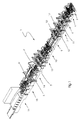
- the folding box gluing machine 1 starts in Fig. 1 bottom right with a depositor 2, which withdraws the blanks to be processed at high speed from a stack one after the other and feeds one by one to the subsequent processing station. Subsequent to the insert 2 follows an alignment station 4, in which the blanks are individually aligned against a lateral stop.
- transversely positionable machine components in the form of two pairs of belts that serve as conveying elements and can be positioned transversely across actuators.
- Both the preformer 6 and the folding station 7 do not provide transverse positionable machine components in the form of belt pairs as conveying elements, which are positioned transversely with an actuator depending on the type of blank.
- a transverse positionable machine component is arranged in the form of an adhesive applicator, which is also positioned transversely with an actuator, so that an adhesive strip is applied to the folding flaps to be bonded.
- the turning station 9 includes for rotating the blanks about a vertical axis by 90 ° two parallel juxtaposed conveyor lines whose speed is adjustable separately.
- the blanks lie on both conveyor lines so that they are rotated at different speeds of the two conveyor lines.
- the two conveyor lines contain driven rollers as conveying elements. In order to prevent the already folded blank parts from opening, they are held down by a turning device 9, not shown, by a plate-shaped hold-down device.
- the next processing station 13 serves to perform box-type dependent processing operations; For example, further score lines are pre-broken or special folds are performed.
- a second folding station 14 in which the blank parts previously provided with an adhesive seam are folded over by 180 °.
- a transfer station 15 from which the folded, provided with not yet set adhesive seams blanks in all parts exactly aligned the subsequent collection and pressing device 16 are supplied.
- the collecting and pressing device 16 a shingled stream of folded blanks is first formed, which is subsequently held under pressure for some time between conveying press belts, so that the adhesive seams set. All of these processing stations contain funding for the boxes, which are driven by servo motor drives, for example.
- the stands 3, 3 ', 5, 5', 11, 11 ', 12, 12' on both sides of the folding stations 7, 14 are arranged.
- a transmitter of the light curtain in the stand 11 and a corresponding receiver may be arranged in the stand 12. The same applies to the other stands.
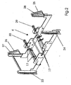
- FIG. 2 described.
- the stands 3, 3 ', 5, 5', 11, 11 ', 12, 12', which are supporting components of the folding box gluing machine 1, are designed in such a way that the elements for the light curtains can be fixed in them and that they at the same time the light curtains 23, 24, 25, 26 can pass.
- longitudinal slots 27, 28 are incorporated in the covering metal shells of the stator, through which the transmitter of the light curtain 23, 24, 25, 26 can cooperate with its associated receiver 23, 24, 25, 26.
- FIG. 2 A corresponding three-dimensional view of the arrangement of the light curtains 23, 24, 25, 26 in the folding station 4 is shown in FIG FIG. 2 played.
- the drives 29, 30 of the Matterholhakens 17, which are designed as a servo-motor drives, located.
- the servo-motor drives 29, 30 are connected directly to the shaft on which the overtaking hooks 17 are attached.
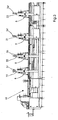
- FIG. 3 a section of a Faltschachtelklebemaschine 18 is shown.
- the folding box gluing machine 18 has several processing stations with one or more uprights 19, 20, 21, 22.
- an area of the machine 18 to be individually set up can now be secured by means of a light curtain.
- the light curtain 23, 24, 25, 26 in response to the activation of hazardous machine parts, in the example of the overtaking hook 17, activated. If no hazardous machine parts are in use, the light curtain 23, 24, 25, 26 is deactivated so that the machine is more accessible to operators. Like from the FIG. 2 also shows, it may happen that the overtaking hooks 17 is arranged very far at the lateral edges of the folding station 7. To the folder gluer and their drives 29, 30 in a correspondingly short time, after the penetration of an operator in the light curtain 23, 24, 25, 26 to stop bring, it may be necessary to arrange the light curtains 25, 26 laterally prominent. A corresponding displacement of the light curtain 25, 26 is in FIG. 2 shown. The lower area of the light curtain 25, 26 projects laterally beyond the installation than the upper area. This may also be necessary if, for example, as in the FIG. 2 illustrated, the servomotors 29, 30 prevents unimpeded operation of the light curtain 25, 26. Thus, the light curtain 25, 26 can also be placed outside of the folding station forming machine parts.
- the machine switches and brakes when the light curtain 23, 24, 25 is interrupted. 26 within a short time.
- the overtaking hooks are stopped, preferably within 0.10 seconds, or in addition the servo-motor conveying drives of the folding box gluing machine 1 are stopped so that they are completely braked within a very short time, for example within 0.25 seconds from a folding box conveying speed of 300 m / min to 0 m / min.
- the folder gluer thus also complies with the guidelines of applicable safety regulations.
- this keypad is designed as a two-hand control unit; ie the safety curtain is only deactivated if the operator has both hands on the control panel.
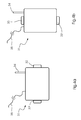
- the control panel as in Fig. 4a and 4b represented, two contacts in the form of, for example, pressure switches (32, 32 ', 33, 33'), which must be operated simultaneously.
- the control panel transmits the deactivation signal either via an antenna 34 on the control panel to an antenna 34 'on the uprights or alternatively via a cable 35 which is connected at one end to the control panel and at its other end in a manner not shown with the stands.
- the state can be as in Fig. 3 exemplified by an acoustic signal in the form of a loudspeaker 36 or a signal lamp 37, which on the uprights (3, 3 ', 11, 11', 12, 12 ', 19, 20, 21, 22) are mounted, are displayed.
Landscapes
- Engineering & Computer Science (AREA)
- General Engineering & Computer Science (AREA)
- Mechanical Engineering (AREA)
- Making Paper Articles (AREA)
- Folding Of Thin Sheet-Like Materials, Special Discharging Devices, And Others (AREA)
- Auxiliary Devices For And Details Of Packaging Control (AREA)
Abstract
Description
- Die Erfindung betrifft eine Faltschachtelklebemaschine für die Verarbeitung von Faltschachtelzuschnitten, bestehend aus mindestens einem Einleger zum Bestücken einer nachfolgenden Bearbeitungsstation, einer Faltstation, einem Auftragwerk für einen Klebstoff, einer Überleitstation, insbesondere mit einer Ausschleuseeinrichtung, einer Sammel- und Presseinrichtung und einer Sicherheitseinrichtung für ein einen Bediener gefährdendes Maschinenteil.
- Faltschachtelklebemaschinen der gattungsgemäßen Art zur Herstellung von Faltschachteln aus Faltschachtelzuschnitten weisen bekanntermaßen zumindest die folgenden Module als Bearbeitungsstationen auf:
- Einen Einleger, der die zu verarbeitenden Zuschnitte mit hoher Geschwindigkeit aus einem Stapel nacheinander abzieht und einzeln der nachfolgenden ersten Bearbeitungsstation zuführt.
- Ein Auftragwerk für Klebstoffe, üblicherweise Leim, das auf die zu verklebenden Faltlappen einen Klebstoffstreifen aufträgt und
- eine Faltstation, in der die mit einem Klebestreifen versehenen Zuschnittteile zur Herstellung einer Klebeverbindung um 180° umgelegt, also gefaltet werden.
- Im Anschluß an die Faltstation ist üblicherweise eine sogenannte Überleitstation angeordnet, in der die Schachteln gezählt, markiert und ausgeschleust werden können. Danach folgt eine Sammel- und Pressstation, an deren Anfang ein Schuppenstrom aus gefalteten Zuschnitten gebildet wird, der in der Pressstation für einige Zeit unter Druck gehalten wird, damit die beiden Zuschnittteile an der Klebenaht verbunden werden.
- Um Faltungen quer zur Transportrichtung der Faltschachtelzuschnitte durchführen zu können, werden in die Faltschachtelklebemaschine zusätzliche Vorrichtungen eingebaut. Solche Vorrichtungen sind beispielsweise aus der amerikanischen Patentschrift
US 4,119,018 bekannt. Sie werden zur Herstellung von Faltschachteln mit oder ohne Dreiecklappen, wie es bei den 4-Punkt-, 6-Punkt-, Faltboden- oder Spezialschachteln üblich ist, eingesetzt. Bei einer bekannten Vorrichtung dieser Art bestehen die hinteren Faltwerkzeuge aus unterhalb der Transportebene gelagerten Haken, die mit ihren freien abgekröpften Enden den zunächst flach liegenden hinteren Steg von unten angreifen und bei Weitertransport des Zuschnittes diesen überholen, so dass der Steg nach innen umgefaltet wird und flach auf dem Faltschachtelzuschnitt zu liegen kommt. Ein solches Faltwerkzeug wird auch Überholhaken genannt. Um derartige Überholhaken, die sich während des Betriebes der Faltschachtelklebemaschine sehr schnell bewegen für den Bediener der Anlage zu sichern, kann dieser Bereich mit einem Zutrittsschutz, zum Beispiel in Form einer Sicherheitstür, verschlossen werden. Diese Sicherheitsmaßnahmen schränken die Zugänglichkeit der Faltschachtelklebemaschine, insbesondere bei der Verarbeitung von Zuschnitten, die ohne den Einsatz von Überholhaken zu verarbeiten sind, aber unnötig ein. - Aus der
DE 10 2004 022 212 A1 ist eine Faltschachtelklebemaschine mit einer Sicherungseinrichtung in Form eines Lichtvorhangs bekannt. Der Lichtvorhang ist in seitlichen Ständern der Faltschachtelklebemaschine angeordnet und kann wahlweise aktiviert oder deaktiviert werden, je nachdem, ob ein Überholhaken zum Einsatz kommt oder nicht. - Derartige Sicherungseinrichtungen schützen den Maschinenbediener somit vor Verletzungen an Überholwellen / -haken der Maschine. Ein Einstellen der Überholwellen / -haken und des durch erzeugten Faltvorganges der Faltschachtel ist im Stand oder bis zu einer Grundgeschwindigkeit der Maschine von etwa 20 m/min möglich. Sobald jedoch die Geschwindigkeit der Maschine größer als die Grundgeschwindigkeit der Maschine ist, wird der Lichtvorhang der Maschine aktiv geschaltet. Dies bedeutet für den Maschinenbediener, dass er sich außerhalb des Lichtvorhangs befinden muss, um die Maschine auf Produktionsgeschwindigkeit hochfahren zu können.
- Da die seitlichen Ständer, in denen die Sicherheitseinrichtung eingebaut ist, ca. 1 m Abstand zur Maschine haben, ist es für den Bediener nahezu unmöglich, zu beobachten, ob die Prozessabläufe etwa in Maschinenmitte oder im Vorbrecher ordnungsgemäß ablaufen. Somit kann der Maschinenbediener nicht erkennen, wo er eine eventuell vorzunehmende Einstellungsveränderung der Faltelemente zur Anpassung des Faltvorgangs an die Maschinengeschwindigkeit vorzunehmen hat.
- Aus der
DE 103 10 236 B3 ist eine Sicherheitseinrichtung im Ausleger einer Bogen verarbeitenden Maschine bekannt, bei der der Bediener mittels einer Eingabevorrichtung einzelne Zugangsbereiche für die Durchführung einer bevorstehenden Bedienhandlung für ein vorgegebenes Zeitintervall deaktivieren kann. Das Vorsehen einer solchen Deaktivierung bei einer Faltschachtelklebemaschine gemäßDE 10 2004 022 212 A1 birgt aber das Risiko in sich, dass der Bediener versucht ist, in die laufende Maschine hineinzugreifen, um notwendige Einstellungen vorzunehmen, da er beide Hände frei hat. Das Verletzungsrisiko wäre somit nicht ausreichend minimiert. - Es ist daher Aufgabe der vorliegenden Erfindung, eine Faltschachtelklebemaschine für die Verarbeitung von Faltschachtelzuschnitten zu entwickeln, die zum einen den Sicherheitsrichtlinien entspricht und den Bediener somit gegen Gefährdungen schützt, auf der anderen Seite aber die Zugänglichkeit zur Faltschachtelklebemaschine nur in minimalster Weise beeinträchtigt.
- Diese Aufgabe wird erfindungsgemäß gelöst, durch die Merkmale von Anspruch 1.
- Durch den erfindungsgemäßen Einsatz eines mobilen Bedienteils, mit welchem die Sicherheitseinrichtung daktiviert werden kann, wird die Zugänglichkeit zur Faltschachtelklebemaschine verbessert. Um gleichzeitig aber zu verhindern, dass der Bediener mit einer oder beiden Händen in die laufende Maschine greifen kann, muss das mobile Bedienteil zur Deaktivierung der Sicherheitsvorrichtung vom Bediener mit beiden Händen bedient werden. Um dies sicherzustellen, weist das mobile Bedienteil entsprechende Kontakte auf. Wird das mobile Bedienteil nur mit einer Hand, also an einem Kontakt bedient, wird die Sicherheitseinrichtung nicht deaktiviert. Ebenso wird die Sicherheitseinrichtung sofort wieder aktiviert, wenn der Bediener, nachdem er beide Kontakte zur Deaktivierung berührt hat, einen Kontakt wieder loslässt.
- Hierzu sind die Kontakte vorzugsweise an sich gegenüberliegenden Seiten des mobilen Bedienteils, also entweder rechts und links, oder oben und unten, oder an der Ober- und Unterseite angebracht. Hierdurch wird sichergestellt, dass der Bediener tatsächlich beide Hände am mobilen Bedienteil hat, wenn er die Sicherheitseinrichtung deaktiviert.
- In einer bevorzugten Ausführungsform sind die Kontakte als Druckschalter ausgebildet. Sobald der Druck auf einen der Schalter aufgehoben wird, der Bediener also seine Hand vom Schalter nimmt, wird die Sicherheitseinrichtung sofort wieder aktiviert.
- In einer besonders bevorzugten Ausführungsform sind die Kontakte mit einer Vorrichtung zur kapazitiven Messung ausgestattet. Hierdurch wird es ermöglicht, zu messen, ob an beiden Kontakten gleiche Oberflächen anliegen. Es wird beispielsweise vermieden, dass der Bediener das mobile Bedienteil nur mit einer Hand bedient, indem er den anderen Kontakt gegen eine andere Oberfläche drückt. Über die kapazitive Messung könnte somit zwischen Haut und einer anderen Oberfläche beispielsweise einer Maschinenseitenwand unterschieden werden.
- Vorteilhafterweise ist das mobile Bedienteil entweder über ein Kabel oder drahtlos mit der Sicherheitseinrichtung verbunden. Dies ermöglicht es dem Bediener, die Prozessabläufe aus unmittelbarer Nähe zu beobachten. Dennoch sind seine Hände über das mobile Bedienteil geschützt.
- Um dem Bediener eine zusätzliche Hilfe über den Zustand der Sicherheitseinrichtung zu geben, ist es vorteilhaft, den Zustand über ein akustisches oder optisches Signal anzuzeigen.
- Nachfolgend wird die Erfindung anhand eines Ausführungsbeispiels und an Figuren erläutert. Es zeigen:
- Figur 1
- in einer perspektivischen Darstellung beispielhaft einzelne Bearbeitungsstationen einer Faltschachtelklebemaschine,
- Figur 2
- die isometrische Ansicht auf einen Teil der Faltstation der Faltschachtelklebemaschine gemäß
Figur 1 - Figur 3
- die Seitenansicht auf einen Ausschnitt einer Faltschachtelklebemaschine gemäß
Figur 1 - Figur 4a
- die Draufsicht auf ein Mobilteil zum Deaktivieren der Sicherheitseinrichtung
- Figur 4b
- die Draufsicht auf ein alternatives Mobilteil zum Deaktivieren der Sicherheitseinrichtung
- Die Faltschachtelklebemaschine 1 beginnt in
Fig. 1 rechts unten mit einem Einleger 2, der die zu verarbeitenden Zuschnitte mit hoher Geschwindigkeit aus einem Stapel nacheinander abzieht und einzeln der nachfolgenden Bearbeitungsstation zuführt. Im Anschluss an den Einleger 2 folgt eine Ausrichtstation 4, in der die Zuschnitte einzeln gegen einen seitlichen Anschlag ausgerichtet werden. Durch die Ausrichtstation führen nicht näher dargestellte, quer positionierbare Maschinenkomponenten in Form von zwei Riemenpaaren, die als Förderelemente dienen und über Stellantriebe quer positioniert werden können. Anschließend folgt ein Vorbrecher 6 und eine erste Faltstation 7. Sowohl durch den Vorbrecher 6 als auch durch die Faltstation 7 führen nicht näher dargestellte quer positionierbare Maschinenkomponenten in Form von Riemenpaaren als Förderelemente, die abhängig vom Zuschnittstyp mit einem Stellantrieb quer positioniert werden. Zu Beginn der Faltstation 7 ist eine nicht dargestellte quer positionierbare Maschinenkomponente in Form eines Klebstoffauftragwerkes angeordnet, das ebenfalls mit einem Stellantrieb quer positioniert wird, damit ein Klebestreifen auf den zu verklebenden Faltlappen aufgetragen wird. - Auf die Faltstation 7 folgt eine Drehstation 9 mit einer nachfolgenden weiteren Ausrichtstation 10. Die Drehstation 9 enthält zum Drehen der Zuschnitte um eine senkrechte Achse um 90° zwei parallel nebeneinander angeordnete Förderstrecken, deren Geschwindigkeit getrennt einstellbar ist. Die Zuschnitte liegen auf beiden Förderstrecken auf, so dass sie bei unterschiedlichen Geschwindigkeiten der beiden Förderstrecken gedreht werden. Die beiden Förderstrecken enthalten angetriebene Rollen als Förderelemente. Um die bereits gefalteten Zuschnittsteile am Öffnen zu hindern, werden sie beim Durchlauf durch die Drehstation 9 von einem nicht dargestellten plattenförmigen Niederhalter niedergehalten.
- Die nächste Bearbeitungsstation 13 dient dazu, vom Schachteltyp abhängige Bearbeitungsvorgänge durchzuführen; beispielsweise werden weitere Rilllinien vorgebrochen oder Sonderfaltungen durchgeführt. Anschließend folgt eine zweite Faltstation 14, in der vorher mit einer Klebenaht versehene Zuschnittsteile um 180° umgefaltet werden. Danach folgt eine Überleitstation 15, von der die gefalteten, mit noch nicht abgebundenen Klebenähten versehenen Zuschnitte in allen Teilen exakt ausgerichtet der nachfolgenden Sammel- und Presseinrichtung 16 zugeführt werden. In der Sammel- und Presseinrichtung 16 wird zunächst ein Schuppenstrom aus gefalteten Zuschnitten gebildet, der anschließend zwischen fördernden Pressbändern für einige Zeit unter Druck gehalten wird, damit die Klebenähte abbinden. Alle diese Bearbeitungsstationen enthalten Fördermittel für die Schachteln, die beispielweise mittels servomotorischer Antriebe angetrieben werden.
- In den Faltstationen 7,14 kann ein Überholhaken eingesetzt werden, durch den eine Gefährdung des Bedieners im Betrieb der Faltschachtelklebemaschine hervorgerufen wird. Im Falle eines solchen den Bediener der Anlage gefährdenden Maschinenteils muss dieses Maschinenteil gegen einen Zugriff geschützt sein. Eine mechanische Verriegelung zwischen den Ständern 11, 11', 12, 12' der Faltstation 7 bzw. 3, 3', 5, 5' der Faltstation 14 wirkt sich nachteilig zum Beispiel während des Einrichtens der Maschine, auf die Rüstzeiten aus. Ein erfindungsgemäßer Einsatz eines Lichtvorhangs, der in die Maschine an der gefährdenden Stelle integriert ist, hat aber keinen Einfluss auf die Zugänglichkeit anderer Maschinenteile. Insbesondere da die Ständer gleichzeitig als Träger für zum Beispiel Notausschalter 8 dienen. Wie aus der Draufsicht zu ersehen, sind die Ständer 3, 3', 5, 5', 11, 11', 12, 12' auf beiden Seiten der Faltstationen 7, 14 angeordnet. So kann insbesondere zum Beispiel ein Sender des Lichtvorhangs in dem Ständer 11 und ein entsprechender Empfänger in dem Ständer 12 angeordnet sein. Entsprechendes gilt für die übrigen Ständer.
- Im Weiteren wird die
Figur 2 beschrieben. Die Ständer 3, 3', 5, 5', 11, 11', 12, 12', die tragende Bestandteile der Faltschachtelklebemaschine 1 sind, sind in der Weise ausgeführt, dass die Elemente für die Lichtvorhänge in ihnen befestigt werden können und dass sie gleichzeitig die Lichtvorhänge 23, 24, 25, 26 durchlassen können. Dazu sind in die abdeckenden Blechmäntel der Ständer Längsschlitze 27, 28 eingearbeitet, durch die der Sender des Lichtvorhangs 23, 24, 25, 26 mit seinem zugehörigen Empfänger 23, 24, 25, 26 zusammenarbeiten kann. Eine entsprechende dreidimensionale Ansicht der Anordnung der Lichtvorhänge 23, 24, 25, 26 in der Faltstation 4 ist inFigur 2 wiedergegeben. In derFigur 2 sind ebenfalls die Antriebe 29, 30 des Überholhakens 17, die als servomotorische Antriebe ausgelegt sind, eingezeichnet. Die servomotorischen Antriebe 29, 30 sind unmittelbar an die Welle angeschlossen, auf der die Überholhaken 17 befestigt sind. - In der
Figur 3 ist ein Ausschnitt aus einer Faltschachtelklebemaschine 18 dargestellt. Die Faltschachtelklebemaschine 18 besitzt mehrere Bearbeitungsstationen mit einem oder mehreren Ständern19, 20, 21, 22. Je nach Gefährdung des Bedieners kann nun ein individuell einzurichtender Bereich der Maschine 18 mittels eines Lichtvorhangs gesichert werden. So ist es beispielsweise vorstellbar, den Lichtvorhang zwischen den Ständern 19 und 20 oder zwischen den Ständern 19 und 21 oder zwischen den Ständern 19 und 22 oder den Ständern 20 und 22 oder jeder beliebigen anderen Kombination an Ständern 19, 20, 21, 22 anzuordnen. - Bevorzugt ist der Lichtvorhang 23, 24, 25, 26 in Abhängigkeit der Aktivierung gefährdender Maschinenteile, im Beispiel der Überholhaken 17, aktivierbar. Sind keine gefährdenden Maschinenteile im Einsatz, wird der Lichtvorhang 23, 24, 25, 26 deaktiviert, damit die Maschine für Bedienpersonen besser zugänglich ist.
Wie aus derFigur 2 ebenfalls hervorgeht, kann es vorkommen, dass die Überholhaken 17 sehr weit an den seitlichen Rändern der Faltstation 7 angeordnet ist. Um die Faltschachtelklebemaschine und deren Antriebe 29, 30 in entsprechend kurzer Zeit, nach dem Eindringen eines Bedieners in den Lichtvorhang 23, 24, 25, 26 zum Anhalten zu bringen, kann es notwendig sein, die Lichtvorhänge 25, 26 seitlich vorstehend anzuordnen. Eine entsprechende Verschiebung des Lichtvorhangs 25, 26 ist inFigur 2 dargestellt. Der untere Bereich des Lichtvorhangs 25, 26 steht seitlich weiter über die Anlage hinaus als der obere Bereich. Dies kann auch dann notwendig sein, wenn zum Beispiel, wie in derFigur 2 dargestellt, die Servomotoren 29, 30 ein ungehindertes Arbeiten des Lichtvorhangs 25, 26 verhindert. So kann der Lichtvorhang 25, 26 auch außerhalb von die Faltstation bildenden Maschinenteilen platziert werden. - Ist die Maschine betriebsbereit oder in der Produktion, und nähert sich ein Bediener dem Lichtvorhang 23, 24, 25, 26, so dass er in einen Gefahrenbereich gelangen könnte, so schaltet und bremst die Maschine bei einer Unterbrechung des Lichtvorhangs 23, 24, 25, 26 innerhalb kürzester Zeit ab. Entweder werden nur die Überholhaken selbst, bevorzugt innerhalb von 0,10 Sekunden angehalten, oder zusätzlich werden die servomotorischen Förderantriebe der Faltschachtelklebemaschine 1 angehalten, so dass diese innerhalb kürzester Zeit von der vollständig abgebremst wird, beispielsweise innerhalb von 0,25 Sekunden von einer Faltschachtelfördergeschwindigkeit von 300 m/min auf 0 m/min. In dieser Zeit ist es dem Bediener nicht möglich, vom Bereich außerhalb des Lichtvorhangs 23, 24, 25, 26 in den Gefahrenbereich, zum Beispiel der Überholhaken 17 zu gelangen. Die Faltschachtelklebemaschine entspricht somit ebenfalls den Richtlinien geltender Sicherheitsvorschriften.
- Um es nun dem Bediener zu ermöglichen, Prozessabläufe etwa in Maschinenmitte oder im Vorbrecher zu beobachten, kann er mittels eines mobilen Bedienteils 31 den aktivierten Sicherheitsvorhang deaktivieren. Um dennoch seine Hände gegen Verletzung zu schützen, ist dieses Bedienteil als Zweihandbedienteil ausgeführt; d. h. der Sicherheitsvorhang wird nur deaktiviert, wenn der Bediener beide Hände am Bedienteil hat. Hierzu weist das Bedienteil, wie in
Fig. 4a und 4b dargestellt, zwei Kontakte in Form von beispielsweise Druckschaltern (32, 32', 33, 33') auf, die gleichzeitig betätigt werden müssen. Das Bedienteil überträgt dann das Deaktivierungssignal entweder über eine Antenne 34 am Bedienteil zu einer Antenne 34' an den Ständern oder alternativ über ein Kabel 35, welches mit seinem einen Ende mit dem Bedienteil verbunden ist und mit seinem anderen Ende in nicht näher dargestellter Weise mit den Ständern. - Um dem Bediener eine zusätzliche Hilfe über den Zustand der Sicherheitseinrichtung zu geben, kann der Zustand wie in
Fig. 3 beispielhaft dargestellt über ein akustisches Signal in Form eines Lautsprechers 36 oder einer Signallampe 37, welche auf den Ständern (3, 3', 11, 11', 12, 12', 19, 20, 21, 22) angebracht sind, angezeigt werden. -
1 Faltschachtelklebemaschine 19 Ständer 2 Einleger 20 Ständer 3, 3' Ständer 21 Ständer 4 Ausrichtestation 22 Ständer 5, 5' Ständer 23 Lichtvorhang 6 Vorbrecher 24 Lichtvorhang 7 erste Faltstation 25 Lichtvorhang 8 Notausschalter 26 Lichtvorhang 9 Drehstation 27 Längsschlitz 10 Ausrichtestation 28 Längsschlitz 11, 11' Ständer 29 Antrieb 12, 12' Ständer 30 Antrieb 13 Bearbeitungsstation 31 Mobilteil 14 zweite Faltstation 32, 32' Druckschalter 15 Überleitstation 33, 33' Druckschalter 16 Sammel- und 34 Antenne Presseinrichtung 35 Anschlusskabel 17 Überholhaken 36 Lautsprecher 18 Faltschachtelklebemaschine 37 Signallampe
Claims (8)
- Faltschachtelklebemaschine für die Verarbeitung von Faltschachtelzuschnitten, bestehend aus mindestens einem Einleger (2) zum Bestücken nachfolgender Bearbeitungsstationen, einer Faltstation (7), einem Auftragwerk für einen Klebstoff, einer Überleitstation (15), einer Sammel- und Presseinrichtung (16) und einer Sicherheitseinrichtung für ein bedienergefährdendes Maschinenteil (17), welches als Lichtvorhang (23, 24, 25, 26) ausgebildet ist und in jeweils an den Seiten der Faltschachtelklebemaschine (1) angeordneten Ständern (3, 3', 5, 5', 11, 11', 12, 12') integriert ist
dadurch gekennzeichnet,
dass die Sicherheitseinrichtung über ein mobiles Bedienteil (31), welches mindestens zwei Kontakte (32, 32', 33, 33') aufweist, wobei die Kontakte vom Bediener nur beidhändig gleichzeitig betätigt werden können, deaktivierbar sind. - Faltschachtelklebemaschine nach Anspruch 1,
dadurch gekennzeichnet,
dass mindestens jeweils ein Kontakt (32, 32') an sich gegenüberliegenden Seiten des mobilen Bedienteils angebracht ist. - Faltschachtelklebemaschine nach Anspruch 1,
dadurch gekennzeichnet,
dass mindestens jeweils ein Kontakt (33, 33') auf der Ober- und Unterseite des mobilen Bedienteil angebracht sind. - Faltschachtelklebemaschine nach einem der vorhergehenden Ansprüche,
dadurch gekennzeichnet,
dass die Kontakte (32, 32', 33, 33') als Druckschalter ausgebildet sind. - Faltschachtelklebemaschine nach einem der vorhergehenden Ansprüche,
dadurch gekennzeichnet,
dass die Kontakte mit einer Vorrichtung zur kapazitiven Messung ausgestattet sind. - Faltschachtelklebemaschine nach einem der vorhergehenden Ansprüche,
dadurch gekennzeichnet,
dass das mobile Bedienteil über ein Kabel (35) mit der Sicherheitseinrichtung verbunden ist. - Faltschachtelklebemaschine nach einem der Ansprüche 1 bis 5,
dadurch gekennzeichnet,
dass das mobile Bedienteil drahtlos über Antennen (34, 34') mit der Sicherheitseinrichtung verbunden ist. - Faltschachtelklebemaschine nach einem der vorhergehenden Ansprüche,
dadurch gekennzeichnet,
dass der Zustand der Sicherheitseinrichtung durch ein akustisches (36) oder optisches Signal (37) angezeigt wird.
Priority Applications (1)
| Application Number | Priority Date | Filing Date | Title |
|---|---|---|---|
| PL08104918T PL2033771T3 (pl) | 2007-08-27 | 2008-07-30 | Klejarka do pudełek składanych, o polepszonej dostępności |
Applications Claiming Priority (1)
| Application Number | Priority Date | Filing Date | Title |
|---|---|---|---|
| DE102007040626A DE102007040626A1 (de) | 2007-08-27 | 2007-08-27 | Faltschachtelklebemaschine mit verbesserter Zugänglichkeit |
Publications (3)
| Publication Number | Publication Date |
|---|---|
| EP2033771A2 true EP2033771A2 (de) | 2009-03-11 |
| EP2033771A3 EP2033771A3 (de) | 2013-04-03 |
| EP2033771B1 EP2033771B1 (de) | 2014-06-11 |
Family
ID=40042696
Family Applications (1)
| Application Number | Title | Priority Date | Filing Date |
|---|---|---|---|
| EP08104918.1A Active EP2033771B1 (de) | 2007-08-27 | 2008-07-30 | Faltschachtelklebemaschine mit verbesserter Zugänglichkeit |
Country Status (5)
| Country | Link |
|---|---|
| US (1) | US7678035B2 (de) |
| EP (1) | EP2033771B1 (de) |
| DE (1) | DE102007040626A1 (de) |
| ES (1) | ES2483719T3 (de) |
| PL (1) | PL2033771T3 (de) |
Cited By (1)
| Publication number | Priority date | Publication date | Assignee | Title |
|---|---|---|---|---|
| CN102336033A (zh) * | 2010-07-14 | 2012-02-01 | 海德堡印刷机械股份公司 | 清废设备 |
Families Citing this family (10)
| Publication number | Priority date | Publication date | Assignee | Title |
|---|---|---|---|---|
| DE102008012776A1 (de) | 2008-03-05 | 2009-09-10 | Heidelberger Druckmaschinen Ag | Vorrichtung zum Aufnehmen von Führungselementen und Werkzeugen einer Faltschachtelklebemaschine |
| US7992364B2 (en) * | 2009-03-25 | 2011-08-09 | Rennco Llc | Vertical bagging machine |
| ES2462591T3 (es) | 2010-08-31 | 2014-05-26 | Heidelberger Druckmaschinen Ag | Dispositivo portaútiles |
| EP2594394A1 (de) | 2010-08-31 | 2013-05-22 | Heidelberger Druckmaschinen AG | Inspektionsmodul |
| KR101102837B1 (ko) * | 2011-07-28 | 2012-01-05 | 이재유 | 종이판재의 세로판 홀딩장치 |
| US20130312365A1 (en) * | 2012-05-08 | 2013-11-28 | G.D Societa' Per Azioni | Automatic product packing machine with manual electric drive control |
| DE102012013757A1 (de) | 2012-07-12 | 2014-01-16 | Heidelberger Druckmaschinen Aktiengesellschaft | Werkzeugaufnahmevorrichtung |
| DE102013202832A1 (de) * | 2013-02-21 | 2014-08-21 | Robert Bosch Gmbh | Handwerkzeugmaschine und Verfahren zum Betreiben der Handwerkzeugmaschine |
| US9789645B2 (en) | 2016-01-26 | 2017-10-17 | Elum Inc. | Glue delivery system |
| CN108891082B (zh) * | 2018-08-29 | 2023-09-12 | 天津长荣科技集团股份有限公司 | 糊盒机及其控制方法 |
Citations (3)
| Publication number | Priority date | Publication date | Assignee | Title |
|---|---|---|---|---|
| US4119018A (en) | 1976-05-28 | 1978-10-10 | Vega S.P.A. | Bending unit for a bending-glueing machine |
| DE10310236B3 (de) | 2003-03-08 | 2004-02-26 | Koenig & Bauer Ag | Sicherheitseinrichtung im Ausleger einer bogenverarbeitenden Maschine |
| DE102004022212A1 (de) | 2004-05-04 | 2005-12-01 | Heidelberger Druckmaschinen Ag | Faltsschachtelklebemaschine mit verbesserter Zugänglichkeit |
Family Cites Families (12)
| Publication number | Priority date | Publication date | Assignee | Title |
|---|---|---|---|---|
| US2058668A (en) * | 1930-08-25 | 1936-10-27 | Prosperity Co Inc | Photoelectric safety control |
| IT1210857B (it) * | 1982-02-17 | 1989-09-29 | Augusto Marchetti | Macchina per la sigillatura di scatole di cartone con possibilita' di apertura immediata dell'area di sigillatura in corso di lavoro. |
| CH650722A5 (fr) * | 1983-02-21 | 1985-08-15 | Bobst Sa | Machine pour confectionner des boites pliantes. |
| US4621300A (en) * | 1984-07-05 | 1986-11-04 | Summerer Ray E | Safety monitoring system for punch press operators |
| IT8520590U1 (it) * | 1985-01-24 | 1986-07-24 | Marchetti Augusto | Dispositivo di protezione antinfortunistica per unità di trascinamento a cinghia motorizzata per macchine e nastratrici di scatole di cartone |
| USRE37777E1 (en) * | 1986-10-08 | 2002-07-02 | Jeffrey G. Herman | Switch apparatus requiring the hand of the operator to activate the switch by breaking a light beam |
| CH681882A5 (de) * | 1990-04-12 | 1993-06-15 | Bobst Sa | |
| US5367158A (en) * | 1991-10-25 | 1994-11-22 | Break-A-Beam, Inc. | Photoelectric switch for use with a machine control circuit |
| US5805451A (en) * | 1996-04-12 | 1998-09-08 | Stark Manufacturing, Inc. | Item selection and item loading error proofing apparatus |
| US5746690A (en) * | 1996-06-28 | 1998-05-05 | Omega Automation, Inc. | Method and apparatus for folding an inflatable cushion |
| DE10320522A1 (de) * | 2003-05-02 | 2004-11-25 | Pilz Gmbh & Co. | Verfahren und Vorrichtug zum Steuern eines sicherheitskritischen Prozesses |
| DE102004022217B8 (de) | 2004-05-04 | 2015-12-31 | Masterwork Machinery Co., Ltd. | Faltschachtelklebemaschine zur Herstellung von Faltschachteln aus Zuschnitten |
-
2007
- 2007-08-27 DE DE102007040626A patent/DE102007040626A1/de not_active Withdrawn
-
2008
- 2008-07-30 EP EP08104918.1A patent/EP2033771B1/de active Active
- 2008-07-30 PL PL08104918T patent/PL2033771T3/pl unknown
- 2008-07-30 ES ES08104918.1T patent/ES2483719T3/es active Active
- 2008-08-01 US US12/184,320 patent/US7678035B2/en active Active
Patent Citations (3)
| Publication number | Priority date | Publication date | Assignee | Title |
|---|---|---|---|---|
| US4119018A (en) | 1976-05-28 | 1978-10-10 | Vega S.P.A. | Bending unit for a bending-glueing machine |
| DE10310236B3 (de) | 2003-03-08 | 2004-02-26 | Koenig & Bauer Ag | Sicherheitseinrichtung im Ausleger einer bogenverarbeitenden Maschine |
| DE102004022212A1 (de) | 2004-05-04 | 2005-12-01 | Heidelberger Druckmaschinen Ag | Faltsschachtelklebemaschine mit verbesserter Zugänglichkeit |
Cited By (3)
| Publication number | Priority date | Publication date | Assignee | Title |
|---|---|---|---|---|
| CN102336033A (zh) * | 2010-07-14 | 2012-02-01 | 海德堡印刷机械股份公司 | 清废设备 |
| EP2407286A3 (de) * | 2010-07-14 | 2012-05-23 | Heidelberger Druckmaschinen AG | Vorrichtung zum Durchbrechen von Stegen, die entlang einer Schnittlinie die benachbarten Kanten eines Zuschnitts zusammenhalten |
| CN102336033B (zh) * | 2010-07-14 | 2014-08-20 | 海德堡印刷机械股份公司 | 清废设备 |
Also Published As
| Publication number | Publication date |
|---|---|
| US20090062095A1 (en) | 2009-03-05 |
| EP2033771A3 (de) | 2013-04-03 |
| ES2483719T3 (es) | 2014-08-07 |
| US7678035B2 (en) | 2010-03-16 |
| EP2033771B1 (de) | 2014-06-11 |
| PL2033771T3 (pl) | 2014-10-31 |
| DE102007040626A1 (de) | 2009-03-05 |
Similar Documents
| Publication | Publication Date | Title |
|---|---|---|
| EP2033771B1 (de) | Faltschachtelklebemaschine mit verbesserter Zugänglichkeit | |
| EP1882657B1 (de) | Bogenbremsvorrichtung | |
| DE102004022217B4 (de) | Faltschachtelklebemaschine zur Herstellung von Faltschachteln aus Zuschnitten | |
| EP2452790B1 (de) | Bearbeitungsstation für eine Stanzmaschine und Verfahren zur Probebogenauslage | |
| DE102011107527A1 (de) | Werkzeugaufnahmevorrichtung | |
| EP2722298B1 (de) | Flachbett-Bogenstanz- und/oder -prägemaschine mit Überwachungssensor und Verfahren zum Schnellabschalten derselben | |
| EP2423137A1 (de) | Transportvorrichtung | |
| DE102006049111A1 (de) | Flachbett-Bogenstanzmaschine | |
| EP3138778B1 (de) | Schalenverschliessmaschine | |
| EP1593485B1 (de) | Faltschachtelklebemaschine zur Herstellung von Faltschachteln aus Zuschnitten | |
| EP3536416B1 (de) | Verfahren zur überwachung einer fertigungsanlage sowie fertigungsanlage mit einem sicherheitssystem | |
| EP2653420B1 (de) | Verfahren zur Bogenübergabe und Stanzmaschine mit Greifer-Transportsystem | |
| DE102011014858A1 (de) | Stanzstation mit Zurichtvorrichtung | |
| EP2014589A2 (de) | Bogenstanz- und -prägemaschine und Verfahren zur Bogenausrichtung | |
| EP2762432B1 (de) | Überwachungsverfahren zur Kollisionsvermeidung einer Stanzmaschine mit Bremsbürste | |
| DE102007008258A1 (de) | Nickbreaker | |
| EP1593486B1 (de) | Faltschachtelklebemaschine mit verbesserter Zugänglichkeit | |
| DE202007011985U1 (de) | Faltschachterklebemaschine mit verbesserter Zugänglichkeit | |
| EP2572843B1 (de) | Verfahren zum Zurichten eines Stanzwerkzeuges und Bogenstanzstation mit ansaugbarer Abdeckplatte | |
| EP2689924B1 (de) | Werkzeugaufnahmevorrichtung | |
| EP2554345A1 (de) | Bogenstanz- und/oder -prägestation mit druckluftbetätigtem Schließrahmen | |
| EP2644369A1 (de) | Sicheres Bedienkonzept für Faltschachtelklebemaschinen | |
| EP1184127A1 (de) | Bearbeitungsvorrichtung für flache Bögen | |
| AT502040B1 (de) | Ablegewerkzeug | |
| EP4508981A1 (de) | Teigbearbeitungsstation mit schutzabdeckung |
Legal Events
| Date | Code | Title | Description |
|---|---|---|---|
| PUAI | Public reference made under article 153(3) epc to a published international application that has entered the european phase |
Free format text: ORIGINAL CODE: 0009012 |
|
| AK | Designated contracting states |
Kind code of ref document: A2 Designated state(s): AT BE BG CH CY CZ DE DK EE ES FI FR GB GR HR HU IE IS IT LI LT LU LV MC MT NL NO PL PT RO SE SI SK TR |
|
| AX | Request for extension of the european patent |
Extension state: AL BA MK RS |
|
| PUAL | Search report despatched |
Free format text: ORIGINAL CODE: 0009013 |
|
| AK | Designated contracting states |
Kind code of ref document: A3 Designated state(s): AT BE BG CH CY CZ DE DK EE ES FI FR GB GR HR HU IE IS IT LI LT LU LV MC MT NL NO PL PT RO SE SI SK TR |
|
| AX | Request for extension of the european patent |
Extension state: AL BA MK RS |
|
| RIC1 | Information provided on ipc code assigned before grant |
Ipc: F16P 3/14 20060101ALI20130225BHEP Ipc: G01V 8/12 20060101ALI20130225BHEP Ipc: B31B 1/74 20060101ALI20130225BHEP Ipc: B31B 1/26 20060101AFI20130225BHEP |
|
| 17P | Request for examination filed |
Effective date: 20131004 |
|
| RBV | Designated contracting states (corrected) |
Designated state(s): AT BE BG CH CY CZ DE DK EE ES FI FR GB GR HR HU IE IS IT LI LT LU LV MC MT NL NO PL PT RO SE SI SK TR |
|
| RIC1 | Information provided on ipc code assigned before grant |
Ipc: B31B 1/26 20060101AFI20131028BHEP Ipc: B31B 1/74 20060101ALI20131028BHEP Ipc: F16P 3/14 20060101ALI20131028BHEP Ipc: G01V 8/12 20060101ALI20131028BHEP |
|
| AKX | Designation fees paid |
Designated state(s): AT BE BG CH CY CZ DE DK EE ES FI FR GB GR HR HU IE IS IT LI LT LU LV MC MT NL NO PL PT RO SE SI SK TR |
|
| GRAP | Despatch of communication of intention to grant a patent |
Free format text: ORIGINAL CODE: EPIDOSNIGR1 |
|
| INTG | Intention to grant announced |
Effective date: 20140129 |
|
| GRAS | Grant fee paid |
Free format text: ORIGINAL CODE: EPIDOSNIGR3 |
|
| GRAA | (expected) grant |
Free format text: ORIGINAL CODE: 0009210 |
|
| AK | Designated contracting states |
Kind code of ref document: B1 Designated state(s): AT BE BG CH CY CZ DE DK EE ES FI FR GB GR HR HU IE IS IT LI LT LU LV MC MT NL NO PL PT RO SE SI SK TR |
|
| REG | Reference to a national code |
Ref country code: GB Ref legal event code: FG4D Free format text: NOT ENGLISH |
|
| REG | Reference to a national code |
Ref country code: CH Ref legal event code: EP |
|
| REG | Reference to a national code |
Ref country code: IE Ref legal event code: FG4D Free format text: LANGUAGE OF EP DOCUMENT: GERMAN |
|
| REG | Reference to a national code |
Ref country code: AT Ref legal event code: REF Ref document number: 672035 Country of ref document: AT Kind code of ref document: T Effective date: 20140715 |
|
| REG | Reference to a national code |
Ref country code: DE Ref legal event code: R096 Ref document number: 502008011861 Country of ref document: DE Effective date: 20140724 |
|
| REG | Reference to a national code |
Ref country code: ES Ref legal event code: FG2A Ref document number: 2483719 Country of ref document: ES Kind code of ref document: T3 Effective date: 20140807 |
|
| PG25 | Lapsed in a contracting state [announced via postgrant information from national office to epo] |
Ref country code: NO Free format text: LAPSE BECAUSE OF FAILURE TO SUBMIT A TRANSLATION OF THE DESCRIPTION OR TO PAY THE FEE WITHIN THE PRESCRIBED TIME-LIMIT Effective date: 20140911 Ref country code: GR Free format text: LAPSE BECAUSE OF FAILURE TO SUBMIT A TRANSLATION OF THE DESCRIPTION OR TO PAY THE FEE WITHIN THE PRESCRIBED TIME-LIMIT Effective date: 20140912 Ref country code: LT Free format text: LAPSE BECAUSE OF FAILURE TO SUBMIT A TRANSLATION OF THE DESCRIPTION OR TO PAY THE FEE WITHIN THE PRESCRIBED TIME-LIMIT Effective date: 20140611 Ref country code: FI Free format text: LAPSE BECAUSE OF FAILURE TO SUBMIT A TRANSLATION OF THE DESCRIPTION OR TO PAY THE FEE WITHIN THE PRESCRIBED TIME-LIMIT Effective date: 20140611 |
|
| REG | Reference to a national code |
Ref country code: PL Ref legal event code: T3 |
|
| REG | Reference to a national code |
Ref country code: NL Ref legal event code: VDEP Effective date: 20140611 |
|
| REG | Reference to a national code |
Ref country code: LT Ref legal event code: MG4D |
|
| PG25 | Lapsed in a contracting state [announced via postgrant information from national office to epo] |
Ref country code: SE Free format text: LAPSE BECAUSE OF FAILURE TO SUBMIT A TRANSLATION OF THE DESCRIPTION OR TO PAY THE FEE WITHIN THE PRESCRIBED TIME-LIMIT Effective date: 20140611 Ref country code: HR Free format text: LAPSE BECAUSE OF FAILURE TO SUBMIT A TRANSLATION OF THE DESCRIPTION OR TO PAY THE FEE WITHIN THE PRESCRIBED TIME-LIMIT Effective date: 20140611 Ref country code: LV Free format text: LAPSE BECAUSE OF FAILURE TO SUBMIT A TRANSLATION OF THE DESCRIPTION OR TO PAY THE FEE WITHIN THE PRESCRIBED TIME-LIMIT Effective date: 20140611 |
|
| PG25 | Lapsed in a contracting state [announced via postgrant information from national office to epo] |
Ref country code: RO Free format text: LAPSE BECAUSE OF FAILURE TO SUBMIT A TRANSLATION OF THE DESCRIPTION OR TO PAY THE FEE WITHIN THE PRESCRIBED TIME-LIMIT Effective date: 20140611 Ref country code: PT Free format text: LAPSE BECAUSE OF FAILURE TO SUBMIT A TRANSLATION OF THE DESCRIPTION OR TO PAY THE FEE WITHIN THE PRESCRIBED TIME-LIMIT Effective date: 20141013 Ref country code: SK Free format text: LAPSE BECAUSE OF FAILURE TO SUBMIT A TRANSLATION OF THE DESCRIPTION OR TO PAY THE FEE WITHIN THE PRESCRIBED TIME-LIMIT Effective date: 20140611 Ref country code: CZ Free format text: LAPSE BECAUSE OF FAILURE TO SUBMIT A TRANSLATION OF THE DESCRIPTION OR TO PAY THE FEE WITHIN THE PRESCRIBED TIME-LIMIT Effective date: 20140611 Ref country code: EE Free format text: LAPSE BECAUSE OF FAILURE TO SUBMIT A TRANSLATION OF THE DESCRIPTION OR TO PAY THE FEE WITHIN THE PRESCRIBED TIME-LIMIT Effective date: 20140611 |
|
| PG25 | Lapsed in a contracting state [announced via postgrant information from national office to epo] |
Ref country code: IS Free format text: LAPSE BECAUSE OF FAILURE TO SUBMIT A TRANSLATION OF THE DESCRIPTION OR TO PAY THE FEE WITHIN THE PRESCRIBED TIME-LIMIT Effective date: 20141011 Ref country code: NL Free format text: LAPSE BECAUSE OF FAILURE TO SUBMIT A TRANSLATION OF THE DESCRIPTION OR TO PAY THE FEE WITHIN THE PRESCRIBED TIME-LIMIT Effective date: 20140611 |
|
| REG | Reference to a national code |
Ref country code: DE Ref legal event code: R097 Ref document number: 502008011861 Country of ref document: DE |
|
| PG25 | Lapsed in a contracting state [announced via postgrant information from national office to epo] |
Ref country code: MC Free format text: LAPSE BECAUSE OF FAILURE TO SUBMIT A TRANSLATION OF THE DESCRIPTION OR TO PAY THE FEE WITHIN THE PRESCRIBED TIME-LIMIT Effective date: 20140611 |
|
| PLBE | No opposition filed within time limit |
Free format text: ORIGINAL CODE: 0009261 |
|
| STAA | Information on the status of an ep patent application or granted ep patent |
Free format text: STATUS: NO OPPOSITION FILED WITHIN TIME LIMIT |
|
| RAP2 | Party data changed (patent owner data changed or rights of a patent transferred) |
Owner name: MASTERWORK MACHINERY CO., LTD. |
|
| REG | Reference to a national code |
Ref country code: IE Ref legal event code: MM4A |
|
| PG25 | Lapsed in a contracting state [announced via postgrant information from national office to epo] |
Ref country code: DK Free format text: LAPSE BECAUSE OF FAILURE TO SUBMIT A TRANSLATION OF THE DESCRIPTION OR TO PAY THE FEE WITHIN THE PRESCRIBED TIME-LIMIT Effective date: 20140611 |
|
| REG | Reference to a national code |
Ref country code: DE Ref legal event code: R081 Ref document number: 502008011861 Country of ref document: DE Owner name: MASTERWORK MACHINERY CO., LTD., CN Free format text: FORMER OWNER: HEIDELBERGER DRUCKMASCHINEN AG, 69115 HEIDELBERG, DE Effective date: 20150402 |
|
| 26N | No opposition filed |
Effective date: 20150312 |
|
| REG | Reference to a national code |
Ref country code: GB Ref legal event code: 732E Free format text: REGISTERED BETWEEN 20150514 AND 20150520 |
|
| REG | Reference to a national code |
Ref country code: DE Ref legal event code: R097 Ref document number: 502008011861 Country of ref document: DE Effective date: 20150312 |
|
| REG | Reference to a national code |
Ref country code: CH Ref legal event code: NV Representative=s name: GLN S.A., CH Ref country code: CH Ref legal event code: PUE Owner name: MASTERWORK MACHINERY CO., LTD., CN Free format text: FORMER OWNER: HEIDELBERGER DRUCKMASCHINEN AKTIENGESELLSCHAFT, DE |
|
| REG | Reference to a national code |
Ref country code: FR Ref legal event code: PLFP Year of fee payment: 8 |
|
| PG25 | Lapsed in a contracting state [announced via postgrant information from national office to epo] |
Ref country code: SI Free format text: LAPSE BECAUSE OF FAILURE TO SUBMIT A TRANSLATION OF THE DESCRIPTION OR TO PAY THE FEE WITHIN THE PRESCRIBED TIME-LIMIT Effective date: 20140611 |
|
| PG25 | Lapsed in a contracting state [announced via postgrant information from national office to epo] |
Ref country code: IE Free format text: LAPSE BECAUSE OF NON-PAYMENT OF DUE FEES Effective date: 20140730 |
|
| PG25 | Lapsed in a contracting state [announced via postgrant information from national office to epo] |
Ref country code: BG Free format text: LAPSE BECAUSE OF FAILURE TO SUBMIT A TRANSLATION OF THE DESCRIPTION OR TO PAY THE FEE WITHIN THE PRESCRIBED TIME-LIMIT Effective date: 20140611 |
|
| PG25 | Lapsed in a contracting state [announced via postgrant information from national office to epo] |
Ref country code: MT Free format text: LAPSE BECAUSE OF FAILURE TO SUBMIT A TRANSLATION OF THE DESCRIPTION OR TO PAY THE FEE WITHIN THE PRESCRIBED TIME-LIMIT Effective date: 20140611 Ref country code: CY Free format text: LAPSE BECAUSE OF FAILURE TO SUBMIT A TRANSLATION OF THE DESCRIPTION OR TO PAY THE FEE WITHIN THE PRESCRIBED TIME-LIMIT Effective date: 20140611 |
|
| REG | Reference to a national code |
Ref country code: FR Ref legal event code: PLFP Year of fee payment: 9 |
|
| PG25 | Lapsed in a contracting state [announced via postgrant information from national office to epo] |
Ref country code: BE Free format text: LAPSE BECAUSE OF FAILURE TO SUBMIT A TRANSLATION OF THE DESCRIPTION OR TO PAY THE FEE WITHIN THE PRESCRIBED TIME-LIMIT Effective date: 20140731 Ref country code: TR Free format text: LAPSE BECAUSE OF FAILURE TO SUBMIT A TRANSLATION OF THE DESCRIPTION OR TO PAY THE FEE WITHIN THE PRESCRIBED TIME-LIMIT Effective date: 20140611 Ref country code: LU Free format text: LAPSE BECAUSE OF NON-PAYMENT OF DUE FEES Effective date: 20140730 Ref country code: HU Free format text: LAPSE BECAUSE OF FAILURE TO SUBMIT A TRANSLATION OF THE DESCRIPTION OR TO PAY THE FEE WITHIN THE PRESCRIBED TIME-LIMIT; INVALID AB INITIO Effective date: 20080730 |
|
| REG | Reference to a national code |
Ref country code: AT Ref legal event code: PC Ref document number: 672035 Country of ref document: AT Kind code of ref document: T Owner name: MASTERWORK MACHINERY CO., LTD., CN Effective date: 20160725 |
|
| REG | Reference to a national code |
Ref country code: DE Ref legal event code: R079 Ref document number: 502008011861 Country of ref document: DE Free format text: PREVIOUS MAIN CLASS: B31B0001260000 Ipc: B31B0050260000 |
|
| REG | Reference to a national code |
Ref country code: CH Ref legal event code: PFA Owner name: MASTERWORK MACHINERY CO., LTD., CN Free format text: FORMER OWNER: MASTERWORK MACHINERY CO., LTD., CN |
|
| REG | Reference to a national code |
Ref country code: FR Ref legal event code: PLFP Year of fee payment: 10 |
|
| REG | Reference to a national code |
Ref country code: FR Ref legal event code: PLFP Year of fee payment: 11 |
|
| REG | Reference to a national code |
Ref country code: CH Ref legal event code: NV Representative=s name: BOVARD SA NEUCHATEL CONSEILS EN PROPRIETE INTE, CH |
|
| PGFP | Annual fee paid to national office [announced via postgrant information from national office to epo] |
Ref country code: ES Payment date: 20250811 Year of fee payment: 18 |
|
| PGFP | Annual fee paid to national office [announced via postgrant information from national office to epo] |
Ref country code: DE Payment date: 20250724 Year of fee payment: 18 |
|
| PGFP | Annual fee paid to national office [announced via postgrant information from national office to epo] |
Ref country code: PL Payment date: 20250714 Year of fee payment: 18 Ref country code: IT Payment date: 20250721 Year of fee payment: 18 |
|
| PGFP | Annual fee paid to national office [announced via postgrant information from national office to epo] |
Ref country code: GB Payment date: 20250722 Year of fee payment: 18 |
|
| PGFP | Annual fee paid to national office [announced via postgrant information from national office to epo] |
Ref country code: FR Payment date: 20250725 Year of fee payment: 18 Ref country code: AT Payment date: 20250718 Year of fee payment: 18 |
|
| PGFP | Annual fee paid to national office [announced via postgrant information from national office to epo] |
Ref country code: CH Payment date: 20250801 Year of fee payment: 18 |
|
| REG | Reference to a national code |
Ref country code: CH Ref legal event code: R18 Free format text: ST27 STATUS EVENT CODE: U-0-0-R10-R18 (AS PROVIDED BY THE NATIONAL OFFICE) Effective date: 20260209 |
|
| REG | Reference to a national code |
Ref country code: CH Ref legal event code: R18 Free format text: ST27 STATUS EVENT CODE: U-0-0-R10-R18 (AS PROVIDED BY THE NATIONAL OFFICE) Effective date: 20260320 |