EP2033836A2 - Chariot de manutention doté d'un mode de conduite et d'un mode de frein - Google Patents
Chariot de manutention doté d'un mode de conduite et d'un mode de frein Download PDFInfo
- Publication number
- EP2033836A2 EP2033836A2 EP08014118A EP08014118A EP2033836A2 EP 2033836 A2 EP2033836 A2 EP 2033836A2 EP 08014118 A EP08014118 A EP 08014118A EP 08014118 A EP08014118 A EP 08014118A EP 2033836 A2 EP2033836 A2 EP 2033836A2
- Authority
- EP
- European Patent Office
- Prior art keywords
- current
- generator
- charging
- charging voltage
- drive
- Prior art date
- Legal status (The legal status is an assumption and is not a legal conclusion. Google has not performed a legal analysis and makes no representation as to the accuracy of the status listed.)
- Withdrawn
Links
Images


Classifications
-
- B—PERFORMING OPERATIONS; TRANSPORTING
- B60—VEHICLES IN GENERAL
- B60W—CONJOINT CONTROL OF VEHICLE SUB-UNITS OF DIFFERENT TYPE OR DIFFERENT FUNCTION; CONTROL SYSTEMS SPECIALLY ADAPTED FOR HYBRID VEHICLES; ROAD VEHICLE DRIVE CONTROL SYSTEMS FOR PURPOSES NOT RELATED TO THE CONTROL OF A PARTICULAR SUB-UNIT
- B60W20/00—Control systems specially adapted for hybrid vehicles
- B60W20/10—Controlling the power contribution of each of the prime movers to meet required power demand
- B60W20/13—Controlling the power contribution of each of the prime movers to meet required power demand in order to stay within battery power input or output limits; in order to prevent overcharging or battery depletion
-
- B—PERFORMING OPERATIONS; TRANSPORTING
- B60—VEHICLES IN GENERAL
- B60K—ARRANGEMENT OR MOUNTING OF PROPULSION UNITS OR OF TRANSMISSIONS IN VEHICLES; ARRANGEMENT OR MOUNTING OF PLURAL DIVERSE PRIME-MOVERS IN VEHICLES; AUXILIARY DRIVES FOR VEHICLES; INSTRUMENTATION OR DASHBOARDS FOR VEHICLES; ARRANGEMENTS IN CONNECTION WITH COOLING, AIR INTAKE, GAS EXHAUST OR FUEL SUPPLY OF PROPULSION UNITS IN VEHICLES
- B60K6/00—Arrangement or mounting of plural diverse prime-movers for mutual or common propulsion, e.g. hybrid propulsion systems comprising electric motors and internal combustion engines
- B60K6/20—Arrangement or mounting of plural diverse prime-movers for mutual or common propulsion, e.g. hybrid propulsion systems comprising electric motors and internal combustion engines the prime-movers consisting of electric motors and internal combustion engines, e.g. HEVs
- B60K6/42—Arrangement or mounting of plural diverse prime-movers for mutual or common propulsion, e.g. hybrid propulsion systems comprising electric motors and internal combustion engines the prime-movers consisting of electric motors and internal combustion engines, e.g. HEVs characterised by the architecture of the hybrid electric vehicle
- B60K6/46—Series type
-
- B—PERFORMING OPERATIONS; TRANSPORTING
- B60—VEHICLES IN GENERAL
- B60L—PROPULSION OF ELECTRICALLY-PROPELLED VEHICLES; SUPPLYING ELECTRIC POWER FOR AUXILIARY EQUIPMENT OF ELECTRICALLY-PROPELLED VEHICLES; ELECTRODYNAMIC BRAKE SYSTEMS FOR VEHICLES IN GENERAL; MAGNETIC SUSPENSION OR LEVITATION FOR VEHICLES; MONITORING OPERATING VARIABLES OF ELECTRICALLY-PROPELLED VEHICLES; ELECTRIC SAFETY DEVICES FOR ELECTRICALLY-PROPELLED VEHICLES
- B60L50/00—Electric propulsion with power supplied within the vehicle
- B60L50/10—Electric propulsion with power supplied within the vehicle using propulsion power supplied by engine-driven generators, e.g. generators driven by combustion engines
- B60L50/15—Electric propulsion with power supplied within the vehicle using propulsion power supplied by engine-driven generators, e.g. generators driven by combustion engines with additional electric power supply
-
- B—PERFORMING OPERATIONS; TRANSPORTING
- B60—VEHICLES IN GENERAL
- B60L—PROPULSION OF ELECTRICALLY-PROPELLED VEHICLES; SUPPLYING ELECTRIC POWER FOR AUXILIARY EQUIPMENT OF ELECTRICALLY-PROPELLED VEHICLES; ELECTRODYNAMIC BRAKE SYSTEMS FOR VEHICLES IN GENERAL; MAGNETIC SUSPENSION OR LEVITATION FOR VEHICLES; MONITORING OPERATING VARIABLES OF ELECTRICALLY-PROPELLED VEHICLES; ELECTRIC SAFETY DEVICES FOR ELECTRICALLY-PROPELLED VEHICLES
- B60L7/00—Electrodynamic brake systems for vehicles in general
- B60L7/10—Dynamic electric regenerative braking
-
- B—PERFORMING OPERATIONS; TRANSPORTING
- B60—VEHICLES IN GENERAL
- B60L—PROPULSION OF ELECTRICALLY-PROPELLED VEHICLES; SUPPLYING ELECTRIC POWER FOR AUXILIARY EQUIPMENT OF ELECTRICALLY-PROPELLED VEHICLES; ELECTRODYNAMIC BRAKE SYSTEMS FOR VEHICLES IN GENERAL; MAGNETIC SUSPENSION OR LEVITATION FOR VEHICLES; MONITORING OPERATING VARIABLES OF ELECTRICALLY-PROPELLED VEHICLES; ELECTRIC SAFETY DEVICES FOR ELECTRICALLY-PROPELLED VEHICLES
- B60L7/00—Electrodynamic brake systems for vehicles in general
- B60L7/20—Braking by supplying regenerated power to the prime mover of vehicles comprising engine-driven generators
-
- B—PERFORMING OPERATIONS; TRANSPORTING
- B60—VEHICLES IN GENERAL
- B60L—PROPULSION OF ELECTRICALLY-PROPELLED VEHICLES; SUPPLYING ELECTRIC POWER FOR AUXILIARY EQUIPMENT OF ELECTRICALLY-PROPELLED VEHICLES; ELECTRODYNAMIC BRAKE SYSTEMS FOR VEHICLES IN GENERAL; MAGNETIC SUSPENSION OR LEVITATION FOR VEHICLES; MONITORING OPERATING VARIABLES OF ELECTRICALLY-PROPELLED VEHICLES; ELECTRIC SAFETY DEVICES FOR ELECTRICALLY-PROPELLED VEHICLES
- B60L7/00—Electrodynamic brake systems for vehicles in general
- B60L7/24—Electrodynamic brake systems for vehicles in general with additional mechanical or electromagnetic braking
-
- B—PERFORMING OPERATIONS; TRANSPORTING
- B60—VEHICLES IN GENERAL
- B60W—CONJOINT CONTROL OF VEHICLE SUB-UNITS OF DIFFERENT TYPE OR DIFFERENT FUNCTION; CONTROL SYSTEMS SPECIALLY ADAPTED FOR HYBRID VEHICLES; ROAD VEHICLE DRIVE CONTROL SYSTEMS FOR PURPOSES NOT RELATED TO THE CONTROL OF A PARTICULAR SUB-UNIT
- B60W10/00—Conjoint control of vehicle sub-units of different type or different function
- B60W10/04—Conjoint control of vehicle sub-units of different type or different function including control of propulsion units
- B60W10/08—Conjoint control of vehicle sub-units of different type or different function including control of propulsion units including control of electric propulsion units, e.g. motors or generators
-
- B—PERFORMING OPERATIONS; TRANSPORTING
- B60—VEHICLES IN GENERAL
- B60W—CONJOINT CONTROL OF VEHICLE SUB-UNITS OF DIFFERENT TYPE OR DIFFERENT FUNCTION; CONTROL SYSTEMS SPECIALLY ADAPTED FOR HYBRID VEHICLES; ROAD VEHICLE DRIVE CONTROL SYSTEMS FOR PURPOSES NOT RELATED TO THE CONTROL OF A PARTICULAR SUB-UNIT
- B60W10/00—Conjoint control of vehicle sub-units of different type or different function
- B60W10/24—Conjoint control of vehicle sub-units of different type or different function including control of energy storage means
- B60W10/26—Conjoint control of vehicle sub-units of different type or different function including control of energy storage means for electrical energy, e.g. batteries or capacitors
-
- B—PERFORMING OPERATIONS; TRANSPORTING
- B60—VEHICLES IN GENERAL
- B60W—CONJOINT CONTROL OF VEHICLE SUB-UNITS OF DIFFERENT TYPE OR DIFFERENT FUNCTION; CONTROL SYSTEMS SPECIALLY ADAPTED FOR HYBRID VEHICLES; ROAD VEHICLE DRIVE CONTROL SYSTEMS FOR PURPOSES NOT RELATED TO THE CONTROL OF A PARTICULAR SUB-UNIT
- B60W20/00—Control systems specially adapted for hybrid vehicles
-
- B—PERFORMING OPERATIONS; TRANSPORTING
- B60—VEHICLES IN GENERAL
- B60W—CONJOINT CONTROL OF VEHICLE SUB-UNITS OF DIFFERENT TYPE OR DIFFERENT FUNCTION; CONTROL SYSTEMS SPECIALLY ADAPTED FOR HYBRID VEHICLES; ROAD VEHICLE DRIVE CONTROL SYSTEMS FOR PURPOSES NOT RELATED TO THE CONTROL OF A PARTICULAR SUB-UNIT
- B60W2300/00—Indexing codes relating to the type of vehicle
- B60W2300/12—Trucks; Load vehicles
-
- B—PERFORMING OPERATIONS; TRANSPORTING
- B60—VEHICLES IN GENERAL
- B60Y—INDEXING SCHEME RELATING TO ASPECTS CROSS-CUTTING VEHICLE TECHNOLOGY
- B60Y2200/00—Type of vehicle
- B60Y2200/10—Road Vehicles
- B60Y2200/15—Fork lift trucks, Industrial trucks
-
- Y—GENERAL TAGGING OF NEW TECHNOLOGICAL DEVELOPMENTS; GENERAL TAGGING OF CROSS-SECTIONAL TECHNOLOGIES SPANNING OVER SEVERAL SECTIONS OF THE IPC; TECHNICAL SUBJECTS COVERED BY FORMER USPC CROSS-REFERENCE ART COLLECTIONS [XRACs] AND DIGESTS
- Y02—TECHNOLOGIES OR APPLICATIONS FOR MITIGATION OR ADAPTATION AGAINST CLIMATE CHANGE
- Y02T—CLIMATE CHANGE MITIGATION TECHNOLOGIES RELATED TO TRANSPORTATION
- Y02T10/00—Road transport of goods or passengers
- Y02T10/60—Other road transportation technologies with climate change mitigation effect
- Y02T10/62—Hybrid vehicles
-
- Y—GENERAL TAGGING OF NEW TECHNOLOGICAL DEVELOPMENTS; GENERAL TAGGING OF CROSS-SECTIONAL TECHNOLOGIES SPANNING OVER SEVERAL SECTIONS OF THE IPC; TECHNICAL SUBJECTS COVERED BY FORMER USPC CROSS-REFERENCE ART COLLECTIONS [XRACs] AND DIGESTS
- Y02—TECHNOLOGIES OR APPLICATIONS FOR MITIGATION OR ADAPTATION AGAINST CLIMATE CHANGE
- Y02T—CLIMATE CHANGE MITIGATION TECHNOLOGIES RELATED TO TRANSPORTATION
- Y02T10/00—Road transport of goods or passengers
- Y02T10/60—Other road transportation technologies with climate change mitigation effect
- Y02T10/7072—Electromobility specific charging systems or methods for batteries, ultracapacitors, supercapacitors or double-layer capacitors
Definitions
- the invention relates to an industrial truck, in particular a hybrid drive-seat tractor, with at least one electrically driven driving mode having a drive current flowing in an electric power circuit and a method for controlling an industrial truck according to the preamble of claim 13.
- hybrid driver's seat tractors are particularly suitable because it is there on the one hand at the airport apron long distances between the terminal building and the parking positions of the aircraft cover, while on the other hand, the entrance to the closed, mostly underground baggage handling areas inside the airport building is required. While the latter would hardly be possible with a pure diesel vehicle for emission reasons, pure electric vehicles are suitable because of their limited. Battery capacity limited for coping with outdoor travel.
- a generator driven by an internal combustion engine supplies power to the traction batteries of the vehicle. Consequently, since the batteries are continuously recharged in the engine operating mode, under typical airport operating conditions, i. generally about 70-90% outdoor use, 10-30% indoor use, external battery charging e.g. Not required in a battery charging station and / or changing the batteries. This is of great advantage in the continuous multi-shift operation - which is the rule at airports.
- hybrid driver's seat tractors Due to the design, a distinction is made in hybrid driver's seat tractors between so-called serial hybrid systems and parallel hybrid systems.
- a parallel hybrid system there are two parallel drive trains: In an electromotive operating mode, the drive wheels are driven by the electric motor. By contrast, in an internal combustion engine operating mode, the drive wheels are directly driven by the diesel engine, with power transmission typically hydrostatic.
- serial hybrid systems on the other hand, there is no mechanical and / or hydraulic connection between the internal combustion engine and the drive wheels. Instead, the drive wheels are always driven by the electric motor. When the internal combustion engine is switched on, it only generates the power required to operate the electric motor and / or recharge the batteries.
- Modern hybrid driver's seat tractors usually have a so-called recuperation brake with which a part of the kinetic energy to be degraded during braking is recovered as electrical energy and fed into the batteries of the vehicle.
- Hybrid driver's seat tractors usually have not only a single recuperation mode, but mostly six or more Rekuperationsmodi, for which often in the electronic driving control various braking ramps are deposited with different braking power: 1. Rekuperationsbremse when the driver while driving takes the foot off the accelerator pedal and / or switches the direction switch from the forward or reverse position to the neutral position (removal of the direction signal), 2. Rekuperationsbremse when the driver while driving the direction switch from "forward" to "reverse” or vice versa 4. Rekuperationsbremse for realizing intentional speed changes, in particular Sollwertreduzi für the accelerator pedal, 4. Rekuperationsbremse when the driver, for example, from a ..
- combustion engine operating mode changes to an electrical operating mode and / or from a normal Fah in a ramp or crawl mode, as far as maximum speeds are provided for these operating modes, which are smaller than the current driving speed, 5.
- tractor unit Characteristic of the tractor unit is that tractor in industry and at airports heavy Pull loads of up to 30 tons. Taking into account that the weight of these tractors is usually between 3.5 and 4.5 tonnes, it becomes clear that the attached load is many times heavier than the tractor itself.
- the strength of the recuperation depends exclusively on the strength of the pulse and the power of the drive motor in the current speed range. This means that if necessary.
- the maximum power or the maximum torque of the drive motor is used to prevent unwanted acceleration of the tractor.
- three-phase drives in tractors are typically designed by a specific winding so that their torque is very high at low speeds and decreases at increasing speeds.
- a characteristic feature of lead-acid accumulators in particular is that the electro-chemical processes during loading and unloading of the traction batteries are sluggish and therefore take place with a certain time delay.
- the lead obtained from the dissolved lead sulfate must be transported to the electrode surface, so that the comparatively low diffusion rate of the lead ions (Pb2 +) is a limiting factor in the absorption of short-term charging currents.
- Rekuperationsströme that are characterized by a high current slew rate and a high amount of current, i. especially "current spikes", can therefore only be recorded even by an uncharged battery limited.
- the drive motor changes to recuperation mode within fractions of a second.
- the resulting Rekuperationsströme are often very high, firstly because the trailer weight is a multiple of the tractor weight, secondly because the trailer due to the non-existing positive connection only delayed participation in the delay curve of the tractor, so that the resulting delay values are very high, there third, if necessary, the full torque of the drive motor is used to prevent unwanted acceleration, and fourthly, that the torque of the drive motor is particularly high, especially in the typical for trailer operation, low to medium speed ranges.
- the problem outlined can occur with empty batteries as well as with fully charged batteries and with new batteries as well as with old ones.
- an increasing degree of saturation or state of charge of the batteries and / or an increasing age of the batteries constitute Boundary conditions that contribute to the tightening of the outlined problem.
- a safety shutdown of the driving control, in particular AC inverter, is currently carried out e.g. in the model "AC 3 Power" of the leading manufacturer ZAPI, for example, at 115 volts.
- a fixed time interval - e.g. by means of a timing relay - defined, after the elapsed of the generator after charging voltage and / or charging current reduction is raised again to its output power.
- a disadvantage of this approach is in particular the following facts: If the time interval for the charging voltage and / or Zadestromreduzi für -defined, a coincidence of Rekuperations- and charging current can not be reliably excluded; if, on the other hand, it is chosen too long, this can significantly worsen the energy balance of a corresponding vehicle because, if appropriate, the generator hardly charges the battery, depending on the application profile.
- the object of the invention is in contrast to propose a method or an industrial truck, in particular a hybrid drive-seat tractor, wherein the disadvantages of the prior art are substantially avoided.
- an industrial truck or method according to the invention is characterized in that the control unit is designed to control the generator power or the charging voltage provided by the latter and / or the charging current generated by it as a function of the current direction in the power circuit.
- a complete or partial charging voltage and / or charging current reduction can advantageously be realized independently of the accelerator pedal position. Accordingly, a particularly cost-effective solution is proposed that the disadvantages of the prior art or especially the problem of induced by current or voltage spikes self-shutdown and / or damage to the driving control and / or other electronic and / or electrical vehicle components when occurring completely or not completely removed by the battery absorbable recuperation.
- control unit is designed to control the generator or the charging voltage provided by the generator and / or the charging current generated by the latter as a function of the current direction and the current intensity of the electric current in the power circuit. This makes it possible that, for example, at very low currents, no complete charge current reduction takes place in order to temporarily store the energy generated by the internal combustion engine at least partially with the aid of the electrical storage means and to use it later or as needed.
- At least one sensor unit comprising a sensor for detecting the current direction and / or the current intensity of the electric current in Power circuit provided.
- a single sensor unit or separate sensor units with correspondingly special sensors can be used here.
- the senor is designed as a measuring resistor.
- Such measuring resistors or so-called shunts are already in use in electronics, so that it is possible to resort to commercially available components. This increases the economy of the invention.
- control unit has at least one AC inverter.
- Corresponding AC inverters are installed in rotary current-operated hybrid driver-seat tractors according to the prior art as drive control. As a rule, therefore, no additional components or components are required, the profitability of the invention is further improved.
- the modulation of the generator power or the charging voltage provided by the generator and / or the charging current generated by the latter is provided as a function of the current strength of the recuperation current and / or the state of charge of the storage means and / or depending on the age of the storage means. In this way, an optimal trade-off between the operational safety and the energy balance of a corresponding vehicle depending on particularly relevant conditions or parameters of the truck can be done.
- Such an increase of the charging voltage and / or the charging current can either to the initial level before the Rekuperationsvorgang or - especially after prolonged Rekuperationsvor réellen - on the depending on relevant parameters, in particular battery voltage and / or current power consumption of the vehicle, optimal level erfölgen.
- the direction of current flow and current through a sensor in the power circuit of the vehicle for example, a so-called shunt, tapped and forwarded to the generator control, based on the generator power or the charge voltage provided by this and / or the charging current generated by this to modulate.
- This embodiment variant has the advantage that it also works in the special cases in which a purely accelerator-dependent control fails, e.g. Downhill with maximum speed and fully depressed accelerator pedal.
- the approach according to the invention has an improved energy balance compared with an accelerator position-dependent charging voltage and / or charging current reduction Episode.
- For a renewed increase in the charging voltage and / or the charging current according to the invention is carried out as soon as possible after completion of a Rekuperationsvorgangs and not only after the elapse of a predefined time interval, as is the case with a conventional, for example, time relay-controlled control.
- This aspect is particularly important, since a partial or complete charge current reduction in the approach according to the invention is to be expected much more frequently than in an accelerator position-dependent control, namely in particular in the cases in which an accelerator position-dependent control - as shown above - fails.
- a connection between the drive control, in particular an AC inverter or the like, and the generator control is provided. Since the drive control or the AC inverter preferably detects the current direction of current and / or current in real time, it is possible to use the output signal of the drive control or of the AC inverter in order to use generator control to determine the generator power or the charging voltage provided by the generator and / or to modulate the charging current generated by this. Additional components, such as a shunt, are therefore not required in this embodiment.
- the generator power or the charging voltage provided by the generator and / or the charging current generated by the generator as a function of the battery charge state.
- the staggered approach of this embodiment has a further improvement of the energy balance of the vehicle result.
- the proposed system has the advantage that it can reliably ensure the reduction of the charging voltage and / or the charging current even in cases where an accelerator position-dependent control fails.
- the problem described at the outset-a self-disconnection induced by current or voltage peaks and / or damage to the drive control and / or other electronic and / or electrical vehicle components when the recuperation currents can not be received or not completely absorbed by the battery-can thereby be prevented much more reliably than with the systems used so far.
- the proposed system also has the advantage that it can be implemented very inexpensively, with generally no significant or costly additional components are needed.
- the essential components of the system diesel engine with flanged generator, an electronic generator control and a driving control, especially AC inverter - are already available as standard.
- the proposed system works almost wear-free.
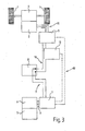
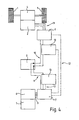
- wheels 1 are driven by an electric motor 2.
- the electric motor 2 is connected via a gear 4 with the wheels 1.
- a drive control 3 which is designed in particular as an AC inverter, controls or controls the electric motor 2.
- an internal combustion engine 5 or diesel engine 5 is provided which generally drives a generator 6 without gear ratio or the like.
- the generator 6 generates electrical energy, which is preferably supplied by means of a generator controller 7, in particular AC inverter, a traction battery 8 by means of lines 9.
- the electrical energy of the generator 6 or diesel engine 5 is supplied to the electric motor 2 by means of the drive control 3 and this accordingly controlled. Accordingly, the illustrated embodiments are serial hybrid vehicles.
- electrical control lines 12 are provided, which are shown in dashed lines in the block diagrams.
- the lines 12 are arranged between the travel control 3 and the generator control 7.
- the electric motor 2 is designed as a generator, i. this generates electrical energy, whereby the wheels 1 are braked.
- the change takes place by the reversal of the current direction in the power 11 or 10 or 9.
- the braking energy is fed into the traction batteries.
- no measuring resistors or shunt resistors are provided.
- This can be regarded as a particularly simple and advantageous embodiment in which the strength of the current fed into the battery 8 is determined purely mathematically by the generator or travel control 7, 3.
- the realization of this variant comprises in particular an advantageous algorithm for converting three-phase current into direct current.
- a measuring resistor 13 is provided, which is arranged electrically between the generator controller 7 and the traction battery 8.
- the measuring resistor 13 is used here to modulate the power of the generator 6.
- the measuring resistor 13 is arranged between the driving control 3 and the traction battery 8.
- FIG. 4 is a fourth embodiment of the invention shown wherein both a measuring resistor 13 between the generator controller 7 and the traction battery 8 and wiping the drive control 3 and the traction battery 8 is arranged.
- This is a particularly advantageous variant, since it allows, for example, to modulate the extent or the intensity of the charging voltage and / or charging current reduction as a function of the strength of the recuperation current.
Landscapes
- Engineering & Computer Science (AREA)
- Transportation (AREA)
- Mechanical Engineering (AREA)
- Chemical & Material Sciences (AREA)
- Combustion & Propulsion (AREA)
- Power Engineering (AREA)
- Automation & Control Theory (AREA)
- Physics & Mathematics (AREA)
- Electromagnetism (AREA)
- Electric Propulsion And Braking For Vehicles (AREA)
Applications Claiming Priority (1)
| Application Number | Priority Date | Filing Date | Title |
|---|---|---|---|
| DE102007037690A DE102007037690A1 (de) | 2007-03-02 | 2007-08-09 | Flurförderzeug mit einem Fahrmodus und einem Bremsmodus |
Publications (2)
| Publication Number | Publication Date |
|---|---|
| EP2033836A2 true EP2033836A2 (fr) | 2009-03-11 |
| EP2033836A3 EP2033836A3 (fr) | 2014-09-10 |
Family
ID=40280818
Family Applications (1)
| Application Number | Title | Priority Date | Filing Date |
|---|---|---|---|
| EP08014118.7A Withdrawn EP2033836A3 (fr) | 2007-08-09 | 2008-08-07 | Chariot de manutention doté d'un mode de conduite et d'un mode de frein |
Country Status (2)
| Country | Link |
|---|---|
| EP (1) | EP2033836A3 (fr) |
| DE (1) | DE102007037690A1 (fr) |
Cited By (1)
| Publication number | Priority date | Publication date | Assignee | Title |
|---|---|---|---|---|
| WO2016083295A1 (fr) * | 2014-11-25 | 2016-06-02 | Bayerische Motoren Werke Aktiengesellschaft | Système à plusieurs accumulateurs d'énergie pour réseaux de bord de véhicules à moteur |
Families Citing this family (2)
| Publication number | Priority date | Publication date | Assignee | Title |
|---|---|---|---|---|
| DE102008054478A1 (de) | 2008-12-10 | 2010-06-17 | Zf Friedrichshafen Ag | Antriebssystem für ein elektrisch angetriebenes Fahrzeug |
| DE102010061533A1 (de) * | 2010-12-23 | 2012-06-28 | Dr. Ing. H.C. F. Porsche Aktiengesellschaft | Antriebssystem |
Family Cites Families (10)
| Publication number | Priority date | Publication date | Assignee | Title |
|---|---|---|---|---|
| US4103211A (en) * | 1977-01-26 | 1978-07-25 | General Electric Company | Dynamic drag arrangement for electrically propelled traction vehicles |
| DE4321767A1 (de) * | 1993-06-30 | 1995-01-12 | Linde Ag | Verfahren zum Betreiben eines Flurförderzeugs |
| DE4430670B4 (de) * | 1993-09-02 | 2006-02-23 | Denso Corp., Kariya | Steuervorrichtung für einen elektrischen Generator/Motor für einen Verbrennungsmotor |
| JP3178503B2 (ja) * | 1994-07-01 | 2001-06-18 | 株式会社デンソー | ハイブリッド自動車の制御装置 |
| DE19745094A1 (de) * | 1997-10-11 | 1999-04-15 | Elektrische Automatisierungs U | Steuerung für Elektrohybridfahrzeug |
| GB2417567B (en) * | 2004-08-24 | 2008-07-02 | Linde Material Handling | Industrial truck and method of operating an industrial truck having at least one battery |
| DE102004044263A1 (de) * | 2004-09-10 | 2006-04-06 | Lutz Baur | Fahrzeug, insbesondere Hybrid-Schlepper oder Hybrid-Plattformwagen |
| DE102005016300A1 (de) * | 2005-04-08 | 2006-10-12 | Proton Motor Fuel Cell Gmbh | Antriebssystem und Verfahren zum Betrieb eines Antriebssystems für ein elektrisch betriebenes Fahrzeug |
| DE102005045776A1 (de) * | 2005-09-23 | 2007-04-05 | Mafi Transport-Systeme Gmbh | Hybridschlepper mit oben liegender Batterie |
| CA2623398A1 (fr) * | 2005-09-23 | 2007-04-05 | Afs Trinity Power Corporation | Procede et appareil d'alimentation de dispositifs electoniques et de commande d'une propulsion hybride enfichable comprenant un dispositif de stockage rapide d'energie |
-
2007
- 2007-08-09 DE DE102007037690A patent/DE102007037690A1/de not_active Withdrawn
-
2008
- 2008-08-07 EP EP08014118.7A patent/EP2033836A3/fr not_active Withdrawn
Cited By (3)
| Publication number | Priority date | Publication date | Assignee | Title |
|---|---|---|---|---|
| WO2016083295A1 (fr) * | 2014-11-25 | 2016-06-02 | Bayerische Motoren Werke Aktiengesellschaft | Système à plusieurs accumulateurs d'énergie pour réseaux de bord de véhicules à moteur |
| CN107078535A (zh) * | 2014-11-25 | 2017-08-18 | 宝马股份公司 | 用于机动车车载电网的多蓄能器系统 |
| CN107078535B (zh) * | 2014-11-25 | 2020-12-08 | 宝马股份公司 | 用于机动车车载电网的多蓄能器系统 |
Also Published As
| Publication number | Publication date |
|---|---|
| DE102007037690A1 (de) | 2008-09-04 |
| EP2033836A3 (fr) | 2014-09-10 |
Similar Documents
| Publication | Publication Date | Title |
|---|---|---|
| EP1466772B1 (fr) | Système d'entraînement pour véhicule | |
| DE4446485C2 (de) | Verfahren und Vorrichtung zum Abbremsen eines Kraftfahrzeuges mit Hybridantrieb | |
| DE4133912C2 (fr) | ||
| EP2646305B1 (fr) | Procédé pour faire fonctionner un véhicule et dispositif d'assistance au conducteur | |
| DE4323604C2 (de) | Fahrzeug mit mindestens einem Elektromotor | |
| DE112009002514T5 (de) | Parallele Leistungsquellen für Hybridelektrofahrzeug-Anwendungen | |
| DE102010020906A1 (de) | Verfahren zum energieoptimierten Betrieb eines flurgebundenen Schwerlast-Transportfahrzeugs mit einem elektrischen Fahrantrieb | |
| EP3152102B1 (fr) | Ensemble de véhicules comprenant plusieurs modules de véhicule entraînés | |
| WO2018054880A2 (fr) | Procédé permettant de faire fonctionner un véhicule hybride | |
| DE102008040400A1 (de) | Verfahren und Vorrichtung zum Betrieb eines Hybridantriebs eines Fahrzeuges | |
| DE19914428C1 (de) | Antriebsanordnung für ein Kraftfahrzeug | |
| EP1801003A2 (fr) | Dispositif d'assistance au déplacement d'une remorque de véhicule | |
| EP2918483A2 (fr) | Procédé de man'uvre d'une remorque à essieu tandem au moyen d'un dispositif de man'uvre et dispositif de man'uvre | |
| DE102007037693A1 (de) | Flurförderzeug mit einem Fahrmodus und einem Bremsmodus | |
| DE102021207156A1 (de) | Verfahren zum Betreiben des Antriebsstrangs, Antriebsstrang für eine Arbeitsmaschine und Arbeitsmaschine | |
| EP2033836A2 (fr) | Chariot de manutention doté d'un mode de conduite et d'un mode de frein | |
| EP3548368B1 (fr) | Semi-remorque, camion et procédé de freinage d'une semi-remorque | |
| EP2567859A1 (fr) | Entraînement doté de moteurs ayant différentes courbes caractéristiques de moments | |
| DE102012208462B4 (de) | Vorrichtung zum Betreiben eines Antriebsstrangs | |
| DE102021206653B3 (de) | Verfahren zum Betreiben eines elektrifizierten Antriebsstrangs für eine Arbeitsmaschine, elektrifizierter Antriebsstrang für eine Arbeitsmaschine und Arbeitsmaschine | |
| WO2023156356A1 (fr) | Procédé de régulation de la température dans un véhicule à propulsion électrique | |
| DE102008044032A1 (de) | Verfahren zum Betreiben eines Hybridantriebsstranges eines Fahrzeuges | |
| DE19820900A1 (de) | Verfahren zur Steuerung eines Kraftfahrzeuges mit Elektroantrieb | |
| EP1964708A2 (fr) | Chariot de manutention doté d'un mode de conduite et d'un mode de frein | |
| EP3150424B1 (fr) | Procede et dispositif de gestion d'energie dans un vehicule automobile comprenant au moins deux essieux entraines |
Legal Events
| Date | Code | Title | Description |
|---|---|---|---|
| PUAI | Public reference made under article 153(3) epc to a published international application that has entered the european phase |
Free format text: ORIGINAL CODE: 0009012 |
|
| AK | Designated contracting states |
Kind code of ref document: A2 Designated state(s): AT BE BG CH CY CZ DE DK EE ES FI FR GB GR HR HU IE IS IT LI LT LU LV MC MT NL NO PL PT RO SE SI SK TR |
|
| AX | Request for extension of the european patent |
Extension state: AL BA MK RS |
|
| PUAL | Search report despatched |
Free format text: ORIGINAL CODE: 0009013 |
|
| AK | Designated contracting states |
Kind code of ref document: A3 Designated state(s): AT BE BG CH CY CZ DE DK EE ES FI FR GB GR HR HU IE IS IT LI LT LU LV MC MT NL NO PL PT RO SE SI SK TR |
|
| AX | Request for extension of the european patent |
Extension state: AL BA MK RS |
|
| RIC1 | Information provided on ipc code assigned before grant |
Ipc: B60L 7/10 20060101ALI20140801BHEP Ipc: B60L 7/20 20060101ALI20140801BHEP Ipc: B60L 11/12 20060101AFI20140801BHEP |
|
| REG | Reference to a national code |
Ref country code: DE Ref legal event code: R108 |
|
| AKY | No designation fees paid | ||
| AXX | Extension fees paid |
Extension state: RS Extension state: BA Extension state: MK Extension state: AL |
|
| REG | Reference to a national code |
Ref country code: DE Ref legal event code: R108 Effective date: 20150512 |
|
| STAA | Information on the status of an ep patent application or granted ep patent |
Free format text: STATUS: THE APPLICATION IS DEEMED TO BE WITHDRAWN |
|
| 18D | Application deemed to be withdrawn |
Effective date: 20150311 |