EP2033842A2 - Aménagement intérieur de véhicule automobile doté d'un plancher de chargement basculant pour la division de l'espace de chargement - Google Patents
Aménagement intérieur de véhicule automobile doté d'un plancher de chargement basculant pour la division de l'espace de chargement Download PDFInfo
- Publication number
- EP2033842A2 EP2033842A2 EP08012914A EP08012914A EP2033842A2 EP 2033842 A2 EP2033842 A2 EP 2033842A2 EP 08012914 A EP08012914 A EP 08012914A EP 08012914 A EP08012914 A EP 08012914A EP 2033842 A2 EP2033842 A2 EP 2033842A2
- Authority
- EP
- European Patent Office
- Prior art keywords
- motor vehicle
- floor section
- loading floor
- floor
- vehicle interior
- Prior art date
- Legal status (The legal status is an assumption and is not a legal conclusion. Google has not performed a legal analysis and makes no representation as to the accuracy of the status listed.)
- Granted
Links
Images
Classifications
-
- B—PERFORMING OPERATIONS; TRANSPORTING
- B60—VEHICLES IN GENERAL
- B60R—VEHICLES, VEHICLE FITTINGS, OR VEHICLE PARTS, NOT OTHERWISE PROVIDED FOR
- B60R5/00—Compartments within vehicle body primarily intended or sufficiently spacious for trunks, suit-cases, or the like
- B60R5/04—Compartments within vehicle body primarily intended or sufficiently spacious for trunks, suit-cases, or the like arranged at rear of vehicle
Definitions
- the present invention relates to a motor vehicle interior device with a load floor arranged above a loading floor, which is arranged pivotably about a first pivot axis on the motor vehicle.
- the known motor vehicle interior device comprises a one-piece, plate-shaped loading floor, which is connected via a first pivot axis pivotally connected to a lever part.
- the lever part is in turn arranged pivotably about a second pivot axis on the motor vehicle, wherein the second pivot axis extends parallel to the first pivot axis.
- the loading floor is first pivoted about the first pivot axis, so that it is inclined.
- the lever part is pivoted together with the loading floor to the second pivot axis down, so that the loading floor pivoted into the lower loading floor position is.
- Both in the upper loading floor position and in the lower loading floor position of the loading floor is arranged in a horizontal plane and supported on corresponding bearing surfaces down.
- the known motor vehicle interior with a loading floor has the disadvantage that, on the one hand, the handling of the loading floor is difficult when adjusting between the upper and the lower loading floor position and, on the other hand, the usability of the loading floor for further purposes, such as, for example, a further compartment division, is limited.
- the known motor vehicle interior provides no way to move the cargo floor space saving in a stowed position in which the loading floor is not needed.
- the motor vehicle interior device has a load compartment floor, above which a loading floor is arranged, which is arranged pivotably about a first pivot axis on the motor vehicle.
- the loading floor has two sections, namely a rear loading floor section and a front loading floor section.
- the two loading floor sections are pivotally connected to each other about a second pivot axis, which can be effected for example by means of a hinge.
- the rear cargo floor portion may be pivoted from a use position in which the rear cargo floor portion is arranged in a horizontal plane about the second pivot axis to a non-use position in which the rear cargo floor portion is arranged in an inclined, preferably vertical plane.
- vehicle-side locking means for locking the rear cargo floor portion in the non-use position.
- the rear cargo floor section In the non-use position of the rear cargo floor section is thus on the one hand a front cargo area, which is limited by the front cargo floor portion and thus has a low height, and on the other hand created a rear cargo area, which has a greater height due to the pivoted in the non-use position rear cargo floor portion as the front cargo area and depending on the degree of pivoting of the rear cargo floor section down is completely or partially limited by the fixed load compartment floor.
- the rear cargo floor portion pivoted into the non-use position serves as a cargo space partition in the vehicle direction, so that cargo in the rear cargo area can not be forwardly received under the front cargo floor portion.
- the vehicle-side locking means give the rear cargo floor section in the non-use position while the necessary support.
- recessed compartments may be provided for tools or the like, which are particularly easily accessible by pivoting the rear cargo floor section in the non-use position, without the entire cargo floor would have to be pivoted into a non-use position.
- the rear loading floor section can be pivoted downwards into the non-use position. This is advantageous in that the downwardly tilted rear loading floor section can be locked in a particularly simple manner or supported on the motor vehicle. Furthermore, the downward pivotal movement substantially also corresponds to the engagement direction, in which an operator engages in order to reach an object on the load compartment floor, whereby the handling is sustainably simplified.
- the rear loading floor section can be pivoted into the non-use position by raising the loading floor in the region of the second pivot axis.
- the operator can first raise the cargo floor briefly, so that the rear cargo floor section pivots alone due to its own weight around the second pivot axis and optionally also released from vehicle-side support elements.
- the cargo floor can then be lowered again to bring the rear cargo floor section in its non-use position and lock there. The handling of the loading floor is simplified.
- the rear edge of the rear loading floor section facing away from the front load floor section faces the load compartment floor in the non-use position.
- the trailing edge of the rear loading floor section is supported in a particularly preferred embodiment of the motor vehicle interior device according to the invention in the non-use position on the load compartment floor and / or a side paneling.
- the locking means are provided on the load compartment floor.
- the locking means are provided on a side trim part.
- a side trim part can be, for example, an interior trim part made of plastic, which laterally limits the cargo space.
- the locking means may be screwed for example to the side trim part.
- the locking means are formed integrally with the side trim part in a further preferred embodiment of the motor vehicle interior device according to the invention.
- the locking means are molded onto the side trim part.
- the side trim part may have been produced together with the locking means in the same injection molding process.
- the locking means in a further particularly preferred embodiment of the motor vehicle interior device according to the invention at least one upwardly open receptacle into which the trailing edge of the rear cargo floor section can be introduced.
- the locking means have two upwardly open receptacles, which are arranged one behind the other in the vehicle direction. In this way, the operator has the opportunity to lock the rear cargo floor section with different inclinations in the non-use position.
- the rear loading floor section can be locked in oblique position of the front loading floor section in the non-use position.
- the thus inclined front loading floor section has the advantage that the load deposited thereon always slides in a safe and consistent position.
- the front cargo floor section is inclined such that the front cargo floor section is inclined downward in the vehicle direction ,
- the load compartment floor has a rear load compartment floor section which is concealed in the use position of the rear cargo floor portion of the rear cargo floor portion and accessible in the non-use position of the rear cargo floor portion. In this way, only the fixed load compartment floor or its rear load compartment floor section forms the lower boundary of the rear load compartment area, which thus has a maximum height.
- a receiving compartment preferably a spare wheel compartment
- the receiving compartment or the spare wheel compartment in this embodiment is particularly quick and easy to access, without the entire loading floor would have to be pivoted into a non-use position.
- the front loading floor section is arranged pivotably on the motor vehicle at its section facing away from the rear loading floor section about the first pivot axis.
- At least one projection for supporting the rear loading floor section in the use position is provided on the motor vehicle.
- the projection is in a further particularly preferred embodiment of the motor vehicle interior device according to the invention arranged at the loading edge of a cargo hold opening.
- the loading floor must be raised only in the region of the second pivot axis in order to effect a pivoting of the rear loading floor section about the second pivot axis and thus a release from the support position on the projection.
- a handle preferably an engagement or penetration, provided for lifting the loading floor.
- the front loading floor section can be pivoted in a further particularly advantageous embodiment of the motor vehicle interior device according to the invention about the first pivot axis in a substantially upright stowage position.
- the rear cargo floor section can be pivoted in a further advantageous embodiment of the motor vehicle interior according to the invention about the second pivot axis in a stowed position, in which the rear cargo floor section is arranged parallel to the front cargo floor section.
- the backs of the front cargo floor section and the rear cargo floor section can be folded onto each other.
- the front loading floor section is dimensioned such that the front loading floor section in the stowed position extends to a lower height than the backrest of a vehicle seat arranged in front of the loading floor.
- the front loading floor portion can be pivoted about the first pivot axis in its stowed position, without protruding over the upper edge of the backrest.
- the view of the vehicle occupants to the rear is not restricted.
- only the rear loading floor section has to be pivoted about the second pivot axis into its stowed position parallel to the front loading floor section.
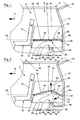
- Fig. 1 shows a side view of the rear part of a motor vehicle 2 with an embodiment of the motor vehicle interior device 4 according to the invention, wherein the vehicle direction is indicated by the arrow 6.
- the motor vehicle 2 has a loading space 8, which is forward through the backrest 10 of a vehicle seat 12 in the rear row of seats, to the rear by a loading edge 14 and a load compartment lid 16, which is open here and a cargo space opening 18 releases down through the load compartment floor 20, is bounded at the top by the vehicle roof 22 and to the sides by the body of the motor vehicle 2, wherein on the sides of the cargo space 8 facing side cover parts 24 are arranged, of which Fig. 1 only one can be seen.
- a loading floor 26 is arranged above the load compartment floor 20.
- the loading floor 26 has a rear loading floor section 28 and a front load floor section 30, which are connected at their mutually facing edges via a hinge 32.
- the two loading floor sections 38, 40 are each plate-shaped and dimensionally stable.
- the front loading floor section 30 is arranged in a section, which faces away from the rear load floor section 28, pivotably about a first pivot axis on the motor vehicle 2 or on the side covering parts 24.
- the front loading floor portion 30 could, for example, have laterally protruding bolts which protrude into corresponding recesses in the side trim parts 24.
- the first pivot axis 34 extends transversely to the vehicle direction 6 and allows pivoting of the entire loading floor 26 about the pivot axis 34.
- the hinge 32 forms a second pivot axis 36, around which the rear and the front loading floor section 28, 30 can be pivoted to each other.
- the second pivot axis 36 also extends transversely to the vehicle direction 6 and parallel to the first pivot axis 34.
- the hinge 32 is formed in this embodiment such that the tops 38, 40 of the rear or front loading floor section 28, 30 regardless of the position of Loading floor 26 always include an angle of at least 180 °. In this way, it is ensured that the upper side 38, 40 of the loading floor sections 28, 30 in the normal position or use position form a coherent, flat surface, which can be easily loaded.
- the rear cargo floor portion 28 is shorter relative to the vehicle direction 6 than the front cargo floor portion 30, whereby the handling of the loading floor 26 is simplified, especially since the operator does not have to bend so far through the load compartment opening 18 in the hold 8 to the penetration 42 to arrive.
- the fixed cargo compartment floor 20 disposed below the cargo floor 26 may be divided into a rear cargo compartment floor section 44 and a front cargo compartment floor section 46, wherein the rear cargo compartment floor section 44 is disposed below the rear cargo floor section 28 and the front cargo compartment floor section 46 is below the front cargo floor section 30 when the cargo floor 26 in the Fig. 1 is shown position.
- a receiving compartment 48 is inserted, for example, the inclusion of a spare wheel (not shown) can serve.
- the automotive interior device 4 further includes vehicle-side locking means 50 for locking the rear cargo floor section 28 in a non-use position, as will be explained in more detail later.
- the locking means 50 may be provided on the load compartment floor 20, but are arranged in the present embodiment, in each case on both side trim parts 24. In this case, the locking means 50 are formed integrally with the side trim parts 24 by the locking means 50 were generated together with the side trim parts 24 in an injection molding process.
- the locking means 50 include three projecting tabs 52, 54, 56 which project inwardly from the side trim members 24 and are raised from the cargo compartment floor 20.
- the projecting lugs 52, 54, 56 are arranged one behind the other in the vehicle direction 6 such that a first upwardly open receptacle 58 is formed between the projecting lugs 52 and 54 and a second upwardly open receptacle 60 is formed between the projecting lugs 54 and 56.
- the first and second receptacles 58, 60 are thus arranged one behind the other in the vehicle direction 6.
- the loading floor 26 is in a normal position. Both the front loading floor section 30 and the rear loading floor section 28 extend in a horizontal plane 62, so that easy loading and unloading of the loading floor 26 is possible.
- the rear loading floor portion 30 facing away from the rear edge 64 of the rear cargo floor portion 28 is supported on a projection 66 which is on the motor vehicle 2, in this case at the loading edge 14 of the cargo compartment opening 18, respectively.
- the rear loading floor section 28 is in a use position in which loading of the upper side 40 of the rear loading floor section 28 is possible.
- the procedure is as follows. First, the loading floor 26 is raised by means of the passage 42 in the region of the second pivot axis 36, as shown in FIG Fig. 2 indicated by the arrow 68. As a result, the rear loading floor section 28 pivots downward about the second pivot axis 36 due to its own weight, so that the overall length of the loading floor 26 in the vehicle direction 6 is shortened. This has the consequence that the trailing edge 64 of the rear cargo floor section 28 is released from the projection 66 and the rear cargo floor section 28 can thus be further pivoted about the second pivot axis 36 downward, as indicated by the arrow 70 in FIG Fig. 2 is indicated.
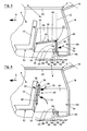
- Fig. 3 By pivoting about the second pivot axis 36 of the rear cargo floor section 28 enters a non-use position, the in Fig. 3 is shown. In the non-use position, the rear loading floor section 28 extends in a vertical or at least inclined plane 72. Now, the operator can lower the loading floor 26 again, so that the trailing edge 64, which now faces the load compartment floor 20, into the first receptacle 58 or second shot 60 be introduced as in Fig. 3 is shown.
- the protruding lugs 52 and 54 - optionally 54 and 56 - prevent further pivoting of the rear cargo floor section 28 about the second pivot axis 36 and provide secure locking of the rear cargo floor section 28 in the disused position. In this non-use position, the trailing edge 64 of the rear cargo floor section 28 is supported on both the cargo compartment floor 20 and the locking means 50.
- the front loading floor portion 30 is pivoted about the first pivot axis 34 and thus inclined when the rear loading floor portion 28 is locked in the non-use position.
- the front loading floor section 30 is set at an angle such that it is inclined downward in the vehicle direction 6. This causes a particularly secure storage of the cargo (not shown) on the top 40 of the front cargo floor portion 30 when the rear cargo floor portion 28 is in the non-use position.
- FIG. 3 it can be seen that the rear load compartment floor section 44, which was still concealed by the rear load floor section 28 in the use position of the rear load floor section 28 ( Fig. 1 ), in the non-use position of the rear cargo floor section 28 is now accessible, so that the operator can easily get to the spare wheel or the like within the receiving compartment 48.
- a particularly high rear area of the cargo space 8 has been created, which is limited only by the rear cargo space floor section 44, whereas a front area of the cargo space 8 is further limited by the front cargo floor portion 30 of the loading floor 26 down.
- the rear loading floor section 28 in the non-use position thus causes a load compartment division, in which prevents cargo from the back between the front cargo compartment floor section 46 and the front cargo floor section 30 can pass.
- Fig. 4 shows a further function of the motor vehicle interior device 4.
- the front loading floor section 30 together with the rear loading floor section 28 of the in Fig. 1 shown normal position about the first pivot axis 34 are pivoted in a substantially upright stowed position, as indicated by the arrow 74.
- the rear cargo floor portion 28 can be pivoted relative to the front cargo floor portion 30 about the second pivot axis 36 to a stowed position, as indicated by the arrow 76, in which the rear cargo floor portion 28 is arranged parallel to the front cargo floor portion 30.
- the bottoms (no reference numeral) of the rear and front cargo floor sections 28, 30 abut each other.
- the front loading floor section 30 is dimensioned such that the front loading floor section 30 extends in the stowed position to a lower height than the backrest 10 of the front of the loading floor 26 arranged vehicle seat 12. In this way, the loading floor 26 can be stowed on the one hand to save space and on the other hand ensures an unobstructed view to the rear.
Landscapes
- Engineering & Computer Science (AREA)
- Mechanical Engineering (AREA)
- Vehicle Step Arrangements And Article Storage (AREA)
- Body Structure For Vehicles (AREA)
Applications Claiming Priority (1)
| Application Number | Priority Date | Filing Date | Title |
|---|---|---|---|
| DE102007042366A DE102007042366A1 (de) | 2007-09-06 | 2007-09-06 | Kraftfahrzeuginneneinrichtung mit einem verschwenkbaren Ladeboden zur Laderaumunterteilung |
Publications (3)
| Publication Number | Publication Date |
|---|---|
| EP2033842A2 true EP2033842A2 (fr) | 2009-03-11 |
| EP2033842A3 EP2033842A3 (fr) | 2010-12-15 |
| EP2033842B1 EP2033842B1 (fr) | 2013-03-13 |
Family
ID=40114420
Family Applications (1)
| Application Number | Title | Priority Date | Filing Date |
|---|---|---|---|
| EP20080012914 Not-in-force EP2033842B1 (fr) | 2007-09-06 | 2008-07-17 | Aménagement intérieur de véhicule automobile doté d'un plancher de chargement basculant pour la division de l'espace de chargement |
Country Status (2)
| Country | Link |
|---|---|
| EP (1) | EP2033842B1 (fr) |
| DE (1) | DE102007042366A1 (fr) |
Cited By (6)
| Publication number | Priority date | Publication date | Assignee | Title |
|---|---|---|---|---|
| FR2950583A1 (fr) * | 2009-09-28 | 2011-04-01 | Peugeot Citroen Automobiles Sa | Dispositif de rangement pour une tablette de fractionnement pour un coffre de vehicule |
| FR2986757A1 (fr) * | 2012-02-13 | 2013-08-16 | Cera | Dispositif de cloisonnement d'un compartiment a bagages de vehicule automobile |
| GB2520804A (en) * | 2013-12-02 | 2015-06-03 | Gm Global Tech Operations Inc | Load compartment arrangement for a vehicle and vehicle with the load compartment arrangement |
| US9073488B1 (en) | 2014-05-30 | 2015-07-07 | Nissan North America, Inc. | Vehicle body structure |
| US9096178B1 (en) | 2014-05-30 | 2015-08-04 | Nissan North America, Inc. | Vehicle body structure |
| US9278647B2 (en) | 2014-05-30 | 2016-03-08 | Nissan North America, Inc. | Vehicle body structure |
Families Citing this family (2)
| Publication number | Priority date | Publication date | Assignee | Title |
|---|---|---|---|---|
| JP5570063B2 (ja) * | 2010-08-24 | 2014-08-13 | 河西工業株式会社 | 車両のラゲージルーム構造 |
| DE102014011565A1 (de) * | 2014-08-02 | 2016-02-04 | GM Global Technology Operations LLC (n. d. Ges. d. Staates Delaware) | Kraftfahrzeug mit multifunktionalem Kofferraumboden |
Citations (1)
| Publication number | Priority date | Publication date | Assignee | Title |
|---|---|---|---|---|
| WO2003104035A1 (fr) | 2002-06-11 | 2003-12-18 | Daimler Chrysler Ag | Plateforme de chargement reglable en hauteur pour vehicule automobile |
Family Cites Families (10)
| Publication number | Priority date | Publication date | Assignee | Title |
|---|---|---|---|---|
| JP2002046540A (ja) * | 2000-08-04 | 2002-02-12 | Kyoraku Co Ltd | 車両用カーゴフロアボックスの蓋体 |
| JP2003002122A (ja) * | 2001-06-21 | 2003-01-08 | Uchihama Kasei Kk | 車室用収容部 |
| JP2003291732A (ja) * | 2002-04-02 | 2003-10-15 | Honda Motor Co Ltd | 自動車用荷室の仕切構造 |
| JP2003341432A (ja) * | 2002-05-27 | 2003-12-03 | Kasai Kogyo Co Ltd | 車両用ラゲージフロアボード構造 |
| DE10305906B4 (de) * | 2003-02-13 | 2006-11-23 | Audi Ag | Ladegutsicherungsvorrichtung im Laderaum eines Kraftfahrzeugs |
| DE102004024609A1 (de) * | 2004-05-18 | 2005-12-22 | Adam Opel Ag | Boden für einen Laderaum eines Kraftfahrzeugs |
| JP2006062618A (ja) * | 2004-08-30 | 2006-03-09 | Kasai Kogyo Co Ltd | 自動車用トノボード装置 |
| JP2006282126A (ja) * | 2005-04-05 | 2006-10-19 | Kasai Kogyo Co Ltd | 車両用ラゲージフロア構造 |
| JP4694977B2 (ja) * | 2006-02-03 | 2011-06-08 | 株式会社パイオラックス | デッキボード |
| US20080030039A1 (en) * | 2006-08-01 | 2008-02-07 | Lear Corporation | Vehicle seat back appendage |
-
2007
- 2007-09-06 DE DE102007042366A patent/DE102007042366A1/de not_active Withdrawn
-
2008
- 2008-07-17 EP EP20080012914 patent/EP2033842B1/fr not_active Not-in-force
Patent Citations (1)
| Publication number | Priority date | Publication date | Assignee | Title |
|---|---|---|---|---|
| WO2003104035A1 (fr) | 2002-06-11 | 2003-12-18 | Daimler Chrysler Ag | Plateforme de chargement reglable en hauteur pour vehicule automobile |
Cited By (7)
| Publication number | Priority date | Publication date | Assignee | Title |
|---|---|---|---|---|
| FR2950583A1 (fr) * | 2009-09-28 | 2011-04-01 | Peugeot Citroen Automobiles Sa | Dispositif de rangement pour une tablette de fractionnement pour un coffre de vehicule |
| FR2986757A1 (fr) * | 2012-02-13 | 2013-08-16 | Cera | Dispositif de cloisonnement d'un compartiment a bagages de vehicule automobile |
| GB2520804A (en) * | 2013-12-02 | 2015-06-03 | Gm Global Tech Operations Inc | Load compartment arrangement for a vehicle and vehicle with the load compartment arrangement |
| US9415725B2 (en) | 2013-12-02 | 2016-08-16 | GM Global Technology Operations LLC | Load compartment arrangement for a vehicle and vehicle with the load compartment arrangement |
| US9073488B1 (en) | 2014-05-30 | 2015-07-07 | Nissan North America, Inc. | Vehicle body structure |
| US9096178B1 (en) | 2014-05-30 | 2015-08-04 | Nissan North America, Inc. | Vehicle body structure |
| US9278647B2 (en) | 2014-05-30 | 2016-03-08 | Nissan North America, Inc. | Vehicle body structure |
Also Published As
| Publication number | Publication date |
|---|---|
| DE102007042366A1 (de) | 2009-03-12 |
| EP2033842A3 (fr) | 2010-12-15 |
| EP2033842B1 (fr) | 2013-03-13 |
Similar Documents
| Publication | Publication Date | Title |
|---|---|---|
| DE102004001092B4 (de) | Verstaubarer Rücksitz für Fahrzeug-Fahrgasträume | |
| DE102014218979B4 (de) | Zusammenklappbare Aufbewahrungsanordnung für einen Rücksitz | |
| DE19705281C2 (de) | Fahrzeug mit Hintersitz | |
| EP2033842B1 (fr) | Aménagement intérieur de véhicule automobile doté d'un plancher de chargement basculant pour la division de l'espace de chargement | |
| DE69915035T2 (de) | Kraftfahrzeug mit verstellbarer Platte | |
| DE102018131250B3 (de) | Verstauung der Kofferraumabdeckung im Frunk | |
| DE60128199T2 (de) | Lieferwagen | |
| DE102007042371A1 (de) | Höhenverstellvorrichtung für den Ladeboden eines Kraftfahrzeugs | |
| DE102007020190A1 (de) | Fahrzeugsitz mit Staufach | |
| EP2878489B1 (fr) | Plancher de chargement d'un véhicule | |
| EP0779172B1 (fr) | Voiture convertible avec deux sièges avant et banquette arrière | |
| EP3387900A1 (fr) | Dispositif de retenue des articles à transporter pour un habitacle d'un vehicule automobile | |
| DE102008036235A1 (de) | Kraftfahrzeugsitz | |
| DE112017004384T5 (de) | Steuerungssystem für eine ausfahrbare Plattform | |
| DE102021105238A1 (de) | Trennwand für ein Fahrzeug | |
| DE102008031015A1 (de) | Personenkraftwagen mit einem verstellbaren Sitz einer mittleren Sitzreihe | |
| DE202006007784U1 (de) | Höhenverstellbarer Ladeboden für Kraftfahrzeuge | |
| DE102010046562B4 (de) | Sitz oder Sitzanlage für ein Kraftfahrzeug und insbesondere einen Lieferwagen | |
| DE10208994B4 (de) | Kraftfahrzeug mit einem heckseitigen Laderaum | |
| DE4202103C2 (de) | Personenkraftwagen mit einer als Wickelsitz ausgeführten Rücksitzanordnung | |
| DE3826959A1 (de) | Kraftfahrzeug mit einer hintersitzanordnung | |
| EP1876056B1 (fr) | Dispositif de recouvrement de coffre et véhicule avec dispositif de recouvrement de coffre | |
| DE202005009428U1 (de) | Innenraumabdeckung für ein Personenkraftfahrzeug | |
| EP1876058B1 (fr) | Véhicule avec des espaces de rangement multiples pour des éléments modulaires | |
| DE102019209982A1 (de) | Heckbaugruppe für ein Kraftfahrzeug, sowie Kraftfahrzeug |
Legal Events
| Date | Code | Title | Description |
|---|---|---|---|
| PUAI | Public reference made under article 153(3) epc to a published international application that has entered the european phase |
Free format text: ORIGINAL CODE: 0009012 |
|
| AK | Designated contracting states |
Kind code of ref document: A2 Designated state(s): AT BE BG CH CY CZ DE DK EE ES FI FR GB GR HR HU IE IS IT LI LT LU LV MC MT NL NO PL PT RO SE SI SK TR |
|
| AX | Request for extension of the european patent |
Extension state: AL BA MK RS |
|
| PUAL | Search report despatched |
Free format text: ORIGINAL CODE: 0009013 |
|
| AK | Designated contracting states |
Kind code of ref document: A3 Designated state(s): AT BE BG CH CY CZ DE DK EE ES FI FR GB GR HR HU IE IS IT LI LT LU LV MC MT NL NO PL PT RO SE SI SK TR |
|
| AX | Request for extension of the european patent |
Extension state: AL BA MK RS |
|
| 17P | Request for examination filed |
Effective date: 20110615 |
|
| RAP1 | Party data changed (applicant data changed or rights of an application transferred) |
Owner name: GM GLOBAL TECHNOLOGY OPERATIONS LLC |
|
| AKX | Designation fees paid |
Designated state(s): AT BE BG CH CY CZ DE DK EE ES FI FR GB GR HR HU IE IS IT LI LT LU LV MC MT NL NO PL PT RO SE SI SK TR |
|
| 17Q | First examination report despatched |
Effective date: 20110926 |
|
| GRAP | Despatch of communication of intention to grant a patent |
Free format text: ORIGINAL CODE: EPIDOSNIGR1 |
|
| GRAS | Grant fee paid |
Free format text: ORIGINAL CODE: EPIDOSNIGR3 |
|
| GRAA | (expected) grant |
Free format text: ORIGINAL CODE: 0009210 |
|
| AK | Designated contracting states |
Kind code of ref document: B1 Designated state(s): AT BE BG CH CY CZ DE DK EE ES FI FR GB GR HR HU IE IS IT LI LT LU LV MC MT NL NO PL PT RO SE SI SK TR |
|
| REG | Reference to a national code |
Ref country code: GB Ref legal event code: FG4D Free format text: NOT ENGLISH |
|
| REG | Reference to a national code |
Ref country code: AT Ref legal event code: REF Ref document number: 600589 Country of ref document: AT Kind code of ref document: T Effective date: 20130315 Ref country code: CH Ref legal event code: EP |
|
| REG | Reference to a national code |
Ref country code: IE Ref legal event code: FG4D Free format text: LANGUAGE OF EP DOCUMENT: GERMAN |
|
| REG | Reference to a national code |
Ref country code: DE Ref legal event code: R096 Ref document number: 502008009442 Country of ref document: DE Effective date: 20130508 |
|
| PG25 | Lapsed in a contracting state [announced via postgrant information from national office to epo] |
Ref country code: BG Free format text: LAPSE BECAUSE OF FAILURE TO SUBMIT A TRANSLATION OF THE DESCRIPTION OR TO PAY THE FEE WITHIN THE PRESCRIBED TIME-LIMIT Effective date: 20130613 Ref country code: SE Free format text: LAPSE BECAUSE OF FAILURE TO SUBMIT A TRANSLATION OF THE DESCRIPTION OR TO PAY THE FEE WITHIN THE PRESCRIBED TIME-LIMIT Effective date: 20130313 Ref country code: ES Free format text: LAPSE BECAUSE OF FAILURE TO SUBMIT A TRANSLATION OF THE DESCRIPTION OR TO PAY THE FEE WITHIN THE PRESCRIBED TIME-LIMIT Effective date: 20130624 Ref country code: LT Free format text: LAPSE BECAUSE OF FAILURE TO SUBMIT A TRANSLATION OF THE DESCRIPTION OR TO PAY THE FEE WITHIN THE PRESCRIBED TIME-LIMIT Effective date: 20130313 Ref country code: NO Free format text: LAPSE BECAUSE OF FAILURE TO SUBMIT A TRANSLATION OF THE DESCRIPTION OR TO PAY THE FEE WITHIN THE PRESCRIBED TIME-LIMIT Effective date: 20130613 |
|
| REG | Reference to a national code |
Ref country code: NL Ref legal event code: VDEP Effective date: 20130313 |
|
| REG | Reference to a national code |
Ref country code: LT Ref legal event code: MG4D |
|
| PG25 | Lapsed in a contracting state [announced via postgrant information from national office to epo] |
Ref country code: FI Free format text: LAPSE BECAUSE OF FAILURE TO SUBMIT A TRANSLATION OF THE DESCRIPTION OR TO PAY THE FEE WITHIN THE PRESCRIBED TIME-LIMIT Effective date: 20130313 Ref country code: LV Free format text: LAPSE BECAUSE OF FAILURE TO SUBMIT A TRANSLATION OF THE DESCRIPTION OR TO PAY THE FEE WITHIN THE PRESCRIBED TIME-LIMIT Effective date: 20130313 Ref country code: SI Free format text: LAPSE BECAUSE OF FAILURE TO SUBMIT A TRANSLATION OF THE DESCRIPTION OR TO PAY THE FEE WITHIN THE PRESCRIBED TIME-LIMIT Effective date: 20130313 Ref country code: GR Free format text: LAPSE BECAUSE OF FAILURE TO SUBMIT A TRANSLATION OF THE DESCRIPTION OR TO PAY THE FEE WITHIN THE PRESCRIBED TIME-LIMIT Effective date: 20130614 |
|
| PG25 | Lapsed in a contracting state [announced via postgrant information from national office to epo] |
Ref country code: HR Free format text: LAPSE BECAUSE OF FAILURE TO SUBMIT A TRANSLATION OF THE DESCRIPTION OR TO PAY THE FEE WITHIN THE PRESCRIBED TIME-LIMIT Effective date: 20130313 |
|
| PG25 | Lapsed in a contracting state [announced via postgrant information from national office to epo] |
Ref country code: SK Free format text: LAPSE BECAUSE OF FAILURE TO SUBMIT A TRANSLATION OF THE DESCRIPTION OR TO PAY THE FEE WITHIN THE PRESCRIBED TIME-LIMIT Effective date: 20130313 Ref country code: NL Free format text: LAPSE BECAUSE OF FAILURE TO SUBMIT A TRANSLATION OF THE DESCRIPTION OR TO PAY THE FEE WITHIN THE PRESCRIBED TIME-LIMIT Effective date: 20130313 Ref country code: IS Free format text: LAPSE BECAUSE OF FAILURE TO SUBMIT A TRANSLATION OF THE DESCRIPTION OR TO PAY THE FEE WITHIN THE PRESCRIBED TIME-LIMIT Effective date: 20130713 Ref country code: PT Free format text: LAPSE BECAUSE OF FAILURE TO SUBMIT A TRANSLATION OF THE DESCRIPTION OR TO PAY THE FEE WITHIN THE PRESCRIBED TIME-LIMIT Effective date: 20130715 Ref country code: CZ Free format text: LAPSE BECAUSE OF FAILURE TO SUBMIT A TRANSLATION OF THE DESCRIPTION OR TO PAY THE FEE WITHIN THE PRESCRIBED TIME-LIMIT Effective date: 20130313 Ref country code: EE Free format text: LAPSE BECAUSE OF FAILURE TO SUBMIT A TRANSLATION OF THE DESCRIPTION OR TO PAY THE FEE WITHIN THE PRESCRIBED TIME-LIMIT Effective date: 20130313 Ref country code: RO Free format text: LAPSE BECAUSE OF FAILURE TO SUBMIT A TRANSLATION OF THE DESCRIPTION OR TO PAY THE FEE WITHIN THE PRESCRIBED TIME-LIMIT Effective date: 20130313 |
|
| PG25 | Lapsed in a contracting state [announced via postgrant information from national office to epo] |
Ref country code: PL Free format text: LAPSE BECAUSE OF FAILURE TO SUBMIT A TRANSLATION OF THE DESCRIPTION OR TO PAY THE FEE WITHIN THE PRESCRIBED TIME-LIMIT Effective date: 20130313 Ref country code: CY Free format text: LAPSE BECAUSE OF FAILURE TO SUBMIT A TRANSLATION OF THE DESCRIPTION OR TO PAY THE FEE WITHIN THE PRESCRIBED TIME-LIMIT Effective date: 20130313 |
|
| PLBE | No opposition filed within time limit |
Free format text: ORIGINAL CODE: 0009261 |
|
| STAA | Information on the status of an ep patent application or granted ep patent |
Free format text: STATUS: NO OPPOSITION FILED WITHIN TIME LIMIT |
|
| BERE | Be: lapsed |
Owner name: GM GLOBAL TECHNOLOGY OPERATIONS LLC Effective date: 20130731 |
|
| PG25 | Lapsed in a contracting state [announced via postgrant information from national office to epo] |
Ref country code: DK Free format text: LAPSE BECAUSE OF FAILURE TO SUBMIT A TRANSLATION OF THE DESCRIPTION OR TO PAY THE FEE WITHIN THE PRESCRIBED TIME-LIMIT Effective date: 20130313 |
|
| 26N | No opposition filed |
Effective date: 20131216 |
|
| PG25 | Lapsed in a contracting state [announced via postgrant information from national office to epo] |
Ref country code: MC Free format text: LAPSE BECAUSE OF FAILURE TO SUBMIT A TRANSLATION OF THE DESCRIPTION OR TO PAY THE FEE WITHIN THE PRESCRIBED TIME-LIMIT Effective date: 20130313 Ref country code: IT Free format text: LAPSE BECAUSE OF FAILURE TO SUBMIT A TRANSLATION OF THE DESCRIPTION OR TO PAY THE FEE WITHIN THE PRESCRIBED TIME-LIMIT Effective date: 20130313 |
|
| REG | Reference to a national code |
Ref country code: CH Ref legal event code: PL |
|
| REG | Reference to a national code |
Ref country code: DE Ref legal event code: R097 Ref document number: 502008009442 Country of ref document: DE Effective date: 20131216 |
|
| REG | Reference to a national code |
Ref country code: IE Ref legal event code: MM4A |
|
| PG25 | Lapsed in a contracting state [announced via postgrant information from national office to epo] |
Ref country code: BE Free format text: LAPSE BECAUSE OF NON-PAYMENT OF DUE FEES Effective date: 20130731 Ref country code: CH Free format text: LAPSE BECAUSE OF NON-PAYMENT OF DUE FEES Effective date: 20130731 Ref country code: LI Free format text: LAPSE BECAUSE OF NON-PAYMENT OF DUE FEES Effective date: 20130731 |
|
| PG25 | Lapsed in a contracting state [announced via postgrant information from national office to epo] |
Ref country code: IE Free format text: LAPSE BECAUSE OF NON-PAYMENT OF DUE FEES Effective date: 20130717 |
|
| REG | Reference to a national code |
Ref country code: AT Ref legal event code: MM01 Ref document number: 600589 Country of ref document: AT Kind code of ref document: T Effective date: 20130717 |
|
| PG25 | Lapsed in a contracting state [announced via postgrant information from national office to epo] |
Ref country code: AT Free format text: LAPSE BECAUSE OF NON-PAYMENT OF DUE FEES Effective date: 20130717 |
|
| REG | Reference to a national code |
Ref country code: FR Ref legal event code: PLFP Year of fee payment: 8 |
|
| PG25 | Lapsed in a contracting state [announced via postgrant information from national office to epo] |
Ref country code: MT Free format text: LAPSE BECAUSE OF FAILURE TO SUBMIT A TRANSLATION OF THE DESCRIPTION OR TO PAY THE FEE WITHIN THE PRESCRIBED TIME-LIMIT Effective date: 20130313 Ref country code: TR Free format text: LAPSE BECAUSE OF FAILURE TO SUBMIT A TRANSLATION OF THE DESCRIPTION OR TO PAY THE FEE WITHIN THE PRESCRIBED TIME-LIMIT Effective date: 20130313 |
|
| PG25 | Lapsed in a contracting state [announced via postgrant information from national office to epo] |
Ref country code: HU Free format text: LAPSE BECAUSE OF FAILURE TO SUBMIT A TRANSLATION OF THE DESCRIPTION OR TO PAY THE FEE WITHIN THE PRESCRIBED TIME-LIMIT; INVALID AB INITIO Effective date: 20080717 Ref country code: LU Free format text: LAPSE BECAUSE OF NON-PAYMENT OF DUE FEES Effective date: 20130717 |
|
| PGFP | Annual fee paid to national office [announced via postgrant information from national office to epo] |
Ref country code: DE Payment date: 20150714 Year of fee payment: 8 Ref country code: GB Payment date: 20150715 Year of fee payment: 8 |
|
| PGFP | Annual fee paid to national office [announced via postgrant information from national office to epo] |
Ref country code: FR Payment date: 20150629 Year of fee payment: 8 |
|
| REG | Reference to a national code |
Ref country code: DE Ref legal event code: R119 Ref document number: 502008009442 Country of ref document: DE |
|
| GBPC | Gb: european patent ceased through non-payment of renewal fee |
Effective date: 20160717 |
|
| PG25 | Lapsed in a contracting state [announced via postgrant information from national office to epo] |
Ref country code: DE Free format text: LAPSE BECAUSE OF NON-PAYMENT OF DUE FEES Effective date: 20170201 Ref country code: FR Free format text: LAPSE BECAUSE OF NON-PAYMENT OF DUE FEES Effective date: 20160801 |
|
| REG | Reference to a national code |
Ref country code: FR Ref legal event code: ST Effective date: 20170331 |
|
| PG25 | Lapsed in a contracting state [announced via postgrant information from national office to epo] |
Ref country code: GB Free format text: LAPSE BECAUSE OF NON-PAYMENT OF DUE FEES Effective date: 20160717 |