EP2033850A2 - Airbag du siège conducteur, dispositif d'airbag du siège conducteur, et appareil de direction - Google Patents
Airbag du siège conducteur, dispositif d'airbag du siège conducteur, et appareil de direction Download PDFInfo
- Publication number
- EP2033850A2 EP2033850A2 EP20080009978 EP08009978A EP2033850A2 EP 2033850 A2 EP2033850 A2 EP 2033850A2 EP 20080009978 EP20080009978 EP 20080009978 EP 08009978 A EP08009978 A EP 08009978A EP 2033850 A2 EP2033850 A2 EP 2033850A2
- Authority
- EP
- European Patent Office
- Prior art keywords
- airbag
- driver
- tether
- seat airbag
- steering wheel
- Prior art date
- Legal status (The legal status is an assumption and is not a legal conclusion. Google has not performed a legal analysis and makes no representation as to the accuracy of the status listed.)
- Withdrawn
Links
- 238000003780 insertion Methods 0.000 claims abstract description 33
- 238000009958 sewing Methods 0.000 description 8
- 238000000034 method Methods 0.000 description 5
- 238000011038 discontinuous diafiltration by volume reduction Methods 0.000 description 3
- 238000005304 joining Methods 0.000 description 2
- 238000005520 cutting process Methods 0.000 description 1
- 230000001419 dependent effect Effects 0.000 description 1
- 239000004744 fabric Substances 0.000 description 1
- 238000004519 manufacturing process Methods 0.000 description 1
- 230000001105 regulatory effect Effects 0.000 description 1
- 238000003466 welding Methods 0.000 description 1
Images



Classifications
-
- B—PERFORMING OPERATIONS; TRANSPORTING
- B60—VEHICLES IN GENERAL
- B60R—VEHICLES, VEHICLE FITTINGS, OR VEHICLE PARTS, NOT OTHERWISE PROVIDED FOR
- B60R21/00—Arrangements or fittings on vehicles for protecting or preventing injuries to occupants or pedestrians in case of accidents or other traffic risks
- B60R21/02—Occupant safety arrangements or fittings, e.g. crash pads
- B60R21/16—Inflatable occupant restraints or confinements designed to inflate upon impact or impending impact, e.g. air bags
- B60R21/23—Inflatable members
- B60R21/231—Inflatable members characterised by their shape, construction or spatial configuration
- B60R21/233—Inflatable members characterised by their shape, construction or spatial configuration comprising a plurality of individual compartments; comprising two or more bag-like members, one within the other
-
- B—PERFORMING OPERATIONS; TRANSPORTING
- B60—VEHICLES IN GENERAL
- B60R—VEHICLES, VEHICLE FITTINGS, OR VEHICLE PARTS, NOT OTHERWISE PROVIDED FOR
- B60R21/00—Arrangements or fittings on vehicles for protecting or preventing injuries to occupants or pedestrians in case of accidents or other traffic risks
- B60R21/02—Occupant safety arrangements or fittings, e.g. crash pads
- B60R21/16—Inflatable occupant restraints or confinements designed to inflate upon impact or impending impact, e.g. air bags
- B60R21/20—Arrangements for storing inflatable members in their non-use or deflated condition; Arrangement or mounting of air bag modules or components
- B60R21/203—Arrangements for storing inflatable members in their non-use or deflated condition; Arrangement or mounting of air bag modules or components in steering wheels or steering columns
-
- B—PERFORMING OPERATIONS; TRANSPORTING
- B60—VEHICLES IN GENERAL
- B60R—VEHICLES, VEHICLE FITTINGS, OR VEHICLE PARTS, NOT OTHERWISE PROVIDED FOR
- B60R21/00—Arrangements or fittings on vehicles for protecting or preventing injuries to occupants or pedestrians in case of accidents or other traffic risks
- B60R21/02—Occupant safety arrangements or fittings, e.g. crash pads
- B60R21/16—Inflatable occupant restraints or confinements designed to inflate upon impact or impending impact, e.g. air bags
- B60R21/23—Inflatable members
- B60R21/231—Inflatable members characterised by their shape, construction or spatial configuration
- B60R21/2334—Expansion control features
- B60R21/2338—Tethers
-
- B—PERFORMING OPERATIONS; TRANSPORTING
- B60—VEHICLES IN GENERAL
- B60R—VEHICLES, VEHICLE FITTINGS, OR VEHICLE PARTS, NOT OTHERWISE PROVIDED FOR
- B60R21/00—Arrangements or fittings on vehicles for protecting or preventing injuries to occupants or pedestrians in case of accidents or other traffic risks
- B60R21/02—Occupant safety arrangements or fittings, e.g. crash pads
- B60R21/16—Inflatable occupant restraints or confinements designed to inflate upon impact or impending impact, e.g. air bags
- B60R21/23—Inflatable members
- B60R21/231—Inflatable members characterised by their shape, construction or spatial configuration
- B60R21/2334—Expansion control features
- B60R21/2338—Tethers
- B60R2021/23382—Internal tether means
Definitions
- the present invention relates to a driver-seat airbag that is quickly inflatable by being reduced in volume at the time of inflation.
- the present invention also relates to a driver-seat airbag device equipped with such a driver-seat airbag, and to a steering apparatus including a steering wheel equipped with such a driver-seat airbag device.
- a driver-seat airbag has a front face at an occupant side and a rear face at a steering-wheel side.
- the central area of the rear face is provided with an inflator-insertion opening.
- the periphery of the inflator-insertion opening in the rear face is attached to an airbag attachment member.
- the airbag inflates.
- the folded body of the driver-seat airbag has attached thereto and is covered with a module cover, thereby forming a driver-seat airbag device.
- a steering wheel has a central portion linked to a steering shaft, a ring portion surrounding the central portion, and spoke portions that connect the central portion and the ring portion. Areas free of the spoke portions between the central portion and the ring portion define openings through which the occupant side and the non-occupant side of the steering wheel spatially communicate with each other.
- the driver-seat airbag device is disposed at the occupant side of the central portion of this steering wheel, and the airbag attachment member is connected to the central portion, thereby forming a steering apparatus.
- the central portion of the steering wheel is positioned on the non-occupant side relative to an occupant-facing surface of the ring portion.
- the airbag attachment member connected to the central portion is also disposed on the non-occupant side relative to the occupant-facing surface of the ring portion. Therefore, when the driver-seat airbag is in an inflated state, an area of the rear face that is near the inflator-insertion opening with the airbag attachment member attached thereto is located at the non-occupant side relative to the occupant-facing surface of the steering wheel.
- Japanese Unexamined Patent Application Publication No. 2002-46568 discloses an airbag whose outer periphery sections are linked to each other with a tether.
- the tether pulls the outer periphery sections of the airbag towards the inside of the airbag so as to reduce the volume of the airbag. Therefore, the airbag can be inflated quickly without the use of a high output inflator.
- an object of the present invention is to provide a driver-seat airbag that can be inflated quickly without the use of a high output inflator and without being reduced in size in the diameter direction of a steering wheel when the airbag is completely inflated.
- Another object of the present invention is to provide a driver-seat airbag device having such a driver-seat airbag, and to provide a steering apparatus including a steering wheel equipped with such a driver-seat airbag device.
- driver-seat airbag as defined in claim 1
- driver-seat airbag device as defined in claim 9
- steering apparatus as defined in claim 10.
- a driver-seat airbag has a front face at an occupant side and a rear face at a steering-wheel side.
- the rear face has an inflator-insertion opening in a central area thereof.
- a tether is connected to an area of the rear face that is near the inflator-insertion opening. When the airbag inflates, the tether pulls a non-occupant side of the rear face, relative to an occupant-facing surface of the steering wheel, towards an inside of the airbag so as to reduce a volume of the airbag.
- the tether is preferably connected to the rear face within a radius range of 100 mm to 175 mm from an axis of the steering wheel in the state where the airbag is inflated.
- the area of the rear face to which the tether is connected preferably overlaps an opening of the steering wheel in the state where the airbag is inflated.
- the tether preferably links sections of the rear face to each other, the sections of the rear face being located at the non-occupant side relative to the occupant-facing surface of the steering wheel in the state where the airbag is inflated.
- the tether preferably extends in a diameter direction of the steering wheel.
- a length L between opposite ends of the tether is preferably 30% to 70% of a distance D between a connection point between one of the opposite ends of the tether and the rear face and a connection point between the other one of the opposite ends of the tether and the rear face in a state where the rear face is laid flat.
- the tether preferably extends crosswise in two directions.
- the tether preferably links the front face to the area of the rear face that is to be located at the non-occupant side relative to the occupant-facing surface of the steering wheel when the airbag is inflated.
- the tether is preferably connected to the front face in an area outside a radius range W of 250 mm to 275 mm from a center of the front face.
- a driver-seat airbag device includes the driver-seat airbag according the invention in a folded state; an airbag attachment member to which a periphery of the inflator-insertion opening in the rear face of the driver-seat airbag is attached; an inflator that inflates the driver-seat airbag; and a module cover that covers a folded body of the driver-seat airbag.
- a steering apparatus includes a steering wheel equipped with the driver-seat airbag device according to the invention.
- the airbag attachment member is disposed at the non-occupant side relative to the occupant-facing surface of the steering wheel.
- the tether pulls the non-occupant side of the rear face, relative to the occupant-facing surface of the steering wheel, towards the inside of the airbag at the time of inflation so as to reduce the volume of the driver-seat airbag. Therefore, without using a high output inflator, the driver-seat airbag can be inflated quickly in response to gas from an inflator.
- the occupant side of the driver-seat airbag relative to the occupant-facing surface of the steering wheel is not or hardly pulled towards the inside of the airbag by the tether.
- This allows for volume reduction of the driver-seat airbag without reducing the size of the airbag in the diameter direction of the steering wheel when the airbag is in its completely inflated state.
- the driver-seat airbag can be deployed quickly over a wide range.
- the tether is preferably connected to the rear face of the driver-seat airbag within a range of 100 mm to 175 mm radially from an axis of the steering wheel in the state where the airbag is inflated.
- the driver-seat airbag when the driver-seat airbag is inflated, an inward area of the rear face relative to the ring portion of the steering wheel is pulled towards the inside of the airbag. In the inflated state of the driver-seat airbag, this inward area of the rear face relative to the ring portion of the steering wheel is located at the non-occupant side relative to the occupant-facing surface of the steering wheel. Therefore, when the driver-seat airbag is inflated, the driver-seat airbag can be reduced in volume while the occupant side of the driver-seat airbag relative to the occupant-facing surface of the steering wheel is not or hardly pulled towards the inside of the airbag.
- the area of the rear face to which the tether is connected preferably overlaps an opening of the steering wheel in the state where the airbag is inflated. Accordingly, this prevents the rear face from bulging outward of the airbag by pushing itself into the opening of the steering wheel as the driver-seat airbag inflates, whereby the driver-seat airbag can be effectively reduced in volume.
- the tether is preferably not connected to the front face of the driver-seat airbag. Therefore, when the driver-seat airbag inflates, the front face can be entirely deployed quickly and substantially evenly towards the occupant side.
- the tether may extend in the diameter direction of the steering wheel.
- the length L between the opposite ends of the tether is preferably 30% to 70% of the distance D between the connection point between one of the opposite ends of the tether and the rear face and the connection point between the other one of the opposite ends of the tether and the rear face in a state where the rear face is laid flat.
- the tether may extend crosswise in two directions.
- the tether is not limited to this shape.
- the tether may extend linearly or may extend radially in three directions or in five or more directions.
- the tether may link the front face of the driver-seat airbag to the area of the rear face that is to be located at the non-occupant side relative to the occupant-facing surface of the steering wheel when the airbag is inflated.
- the tether is preferably connected to the front face in an area outside a radius range W of 250 mm to 275 mm from the center of the front face. Accordingly, when the driver-seat airbag inflates, the wide range W surrounding the center of the front face can be deployed quickly and substantially evenly towards the occupant side without being restrained by the tether.
- Fig. 1(a) is a front view of a steering apparatus including a steering wheel equipped with a driver-seat airbag device having a driver-seat airbag according to an embodiment.
- Fig. 1(b) is a front view showing the airbag of the steering apparatus in an inflated state.
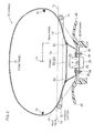
- Fig. 2 is a cross-sectional view taken along line II-II in Fig. 1(b) .
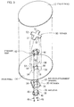
- Fig. 3 is an exploded perspective view of the driver-seat airbag and the driver-seat airbag device.
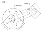
- Fig. 4 is an exploded view of a rear panel and a tether included in the driver-seat airbag.
- the vertical and horizontal directions respectively correspond to vertical and horizontal directions of the steering wheel when the steering wheel is viewed in the forward moving direction of the vehicle.
- a driver-seat airbag (which may sometimes be simply referred to as an "airbag” hereinafter) 10 in a folded state is attached to a retainer 30 serving as an airbag attachment member, and is inflatable by means of an inflator 36.
- the folded body of this airbag 10 has attached thereto and is covered with a module cover 48. Consequently, this forms a driver-seat airbag device (which may sometimes be simply referred to as an "airbag device” hereinafter).
- a steering wheel 1 has a central portion 1a linked to a steering shaft (not shown), a ring portion 1b surrounding the central portion 1a, and spoke portions 1c that connect the central portion 1a and the ring portion 1b.
- spoke portions 1c that connect the central portion 1a and the ring portion 1b.
- a total of three spoke portions 1c extend leftward, rightward, and downward from the central portion 1a, respectively.
- Each spoke portion 1c has an end in the extending direction thereof that is connected to an inner periphery of a corresponding one of left, right, and lower positions of the ring portion 1b.
- Areas free of the spoke portions 1c between the central portion 1a and the ring portion 1b define openings 1d through which the occupant side and the non-occupant side of the steering wheel 1 spatially communicate with each other.
- the airbag device is disposed at the occupant side of the central portion 1a of the steering wheel 1, and the retainer 30 is linked to the central portion 1a, thereby forming a steering apparatus.
- the central portion 1a of the steering wheel 1 is positioned on the non-occupant side relative to an occupant-facing surface 1e ( Fig. 2 ) of the ring portion 1b by an amount corresponding to the thickness of the driver-seat airbag device.
- the retainer 30 linked to the central portion 1a is disposed on the non-occupant side relative to the occupant-facing surface 1e of the ring portion 1b of the steering wheel 1.
- the driver-seat airbag 10 has a front panel 12 defining a front face proximate to the occupant at the time of inflation and a rear panel 14 defining a rear face proximate to the steering wheel 1 at the time of inflation, the front panel 12 and the rear panel 14 being joined to each other by, for example, sewing along the edges thereof so as to form a shape of a bag.
- Reference numeral 15 denotes a seam formed as a result of sewing.
- the front panel 12 and the rear panel 14 are formed of substantially circular cloths with a diameter larger than that of the ring portion 1b of the steering wheel 1.
- a central area of the rear panel 14 is provided with an inflator-insertion opening 16 through which the inflator 36 extends.
- an inflator-insertion opening 16 is arranged around the inflator-insertion opening 16 through which bolts 44 are inserted for fixing the rear panel 14 to the retainer 30.
- an area of the rear panel 14 that is near the inflator-insertion opening 16 has connected thereto a tether 50 for pulling the rear panel 14 towards the inside of the airbag 10 at the time of inflation of the airbag 10 to reduce the volume of the airbag 10.
- the tether 50 substantially has a shape of a cross so as to extend crosswise in two directions.
- one segment of the cross-shaped tether 50 that extends in one of the two directions will be referred to as a first-direction-extending segment 51, whereas the other segment extending in the other one of the two directions will be referred to as a second-direction-extending segment 52.
- the two segments may sometimes be collectively referred to as extending segments 51 and 52.
- the first-direction-extending segment 51 and the second-direction-extending segment 52 have substantially the same end-to-end length L.
- the first-direction-extending segment 51 and the second-direction-extending segment 52 intersect with each other at a substantially right angle at longitudinally intermediate sections thereof.
- the first-direction-extending segment 51 and the second-direction-extending segment 52 may have different lengths.
- the length from the intersection of the first-direction-extending segment 51 and the second-direction-extending segment 52 to the opposite ends thereof may all be the same or be different from each other.
- the intersection angle between the first-direction-extending segment 51 and the second-direction-extending segment 52 may be an angle other than a substantially right angle.
- the first-direction-extending segment 51 traverses the inflator-insertion opening 16 from the upper right to the lower left within the airbag 10 when inflated
- the second-direction-extending segment 52 traverses the inflator-insertion opening 16 from the upper left to the lower right within the airbag 10 when inflated.
- the opposite ends of each of the extending segments 51 and 52 are joined to corresponding locations of the rear panel 14 near the opening 16 and are positioned opposite to each other across the opening 16.
- Reference numeral 53 in Fig. 2 denotes seams at which the opposite ends of each extending segment 51, 52 are sewn to the rear panel 14.
- Double-dotted chain lines 54 in Figs. 3 and 4 indicate planned tether sewing sections of the rear panel 14, to which the opposite ends of each extending segment 51, 52 are to be sewn with the corresponding seams 53.
- the technique for joining the tether 50 (i.e. the opposite ends of each extending segment 51, 52) onto the rear panel 14 is not limited to the aforementioned sewing technique, and other various joining techniques may be applied, such as a bonding technique or a welding technique.
- the tether 50 (i.e. the opposite ends of each extending segment 51, 52) is preferably joined to the rear panel 14 within a radius range r of 100 mm to 175 mm from an axis 1x of the steering wheel 1 (i.e. the axis of the steering shaft) in the state where the airbag 10 is inflated.
- the tether 50 (i.e. the opposite ends of each extending segment 51, 52) is preferably joined to sections of the rear panel 14 where the tether 50 overlaps the openings 1d of the steering wheel 1 when the airbag 10 is inflated.
- each extending segment 51, 52 (which will simply be referred to as "the length of each extending segment 51, 52" hereinafter) is smaller than a distance D between the corresponding planned tether sewing sections 54, 54 positioned opposite to each other across the inflator-insertion opening 16.
- the length L of each extending segment 51, 52 be 30% to 70% of the distance D between the corresponding planned tether sewing sections 54, 54 positioned opposite to each other across the opening 16.
- the retainer 30 to which the airbag 10 is attached has an inflator-attachment opening 32 in the center thereof, and also has bolt through holes 34 that surround the inflator-attachment opening 32.
- the inflator 36 is substantially columnar and has gas outlets 36a on a periphery surface thereof and near one end thereof in the axial direction.
- the inflator 36 is configured to discharge gas radially from these gas outlets 36a.
- a flange 38 for fixing the inflator 36 extends from an axially intermediate position of the periphery surface of the inflator 36 (the intermediate position being closer towards the rear end of the inflator 36 relative to the gas outlets 36a).
- the flange 38 is provided with bolt through holes 40.
- the one end of the inflator 36 is fitted in the inflator-attachment opening 32.
- the periphery of the inflator-insertion opening 16 of the rear panel 14 is first aligned with the periphery of the inflator-attachment opening 32 of the retainer 30 from the occupant side of the retainer 30. Then, the stud bolts 44 of a presser ring 42 are inserted through the bolt through holes 18, 34, and 40 of the rear panel 14, the retainer 30, and the flange 38, respectively. By fastening nuts 46 to the ends of the bolts 44, the rear panel 14 and the inflator 36 become fixed to the retainer 30.
- the airbag 10 is folded, and the module cover 48 is attached to the retainer 30 such that the module cover 48 covers the folded body of the airbag 10, thereby forming the driver-seat airbag device.
- the airbag 10 may be preliminarily folded prior to attaching the airbag 10 to the retainer 30.
- the driver-seat airbag device is disposed at the occupant side of the central portion 1a of the steering wheel 1, and the retainer 30 is linked to the central portion 1a via a bracket (not shown).
- the inflator 36 When a vehicle equipped with this steering apparatus is involved in a collision, the inflator 36 is actuated and discharges gas.
- the gas from the inflator 36 causes the airbag 10 to start to inflate.
- the airbag 10 pushes open the module cover 48 so as to expand towards the occupant side of the steering wheel 1.
- the airbag 10 inflates until the outer periphery thereof extends outward beyond the ring portion 1b of the steering wheel 1.
- the airbag 10 when the airbag 10 inflates, an area of the rear panel 14 that is near the inflator-insertion opening 16 is pulled towards the inside of the airbag 10 by the tether 50, whereby the airbag 10 becomes reduced in volume. Therefore, without using a high output inflator as the inflator 36, the airbag 10 can be inflated quickly in response to the gas from the inflator 36.
- the retainer 30 is disposed at the non-occupant side relative to the occupant-facing surface 1e of the steering wheel 1. This means that, when the airbag 10 is in an inflated state as shown in Fig. 2 , the area of the rear panel 14 of the airbag 10 that is near the inflator-insertion opening 16 connected to the retainer 30 is located at the non-occupant side relative to the occupant-facing surface 1e of the steering wheel 1.
- the tether 50 is connected to the area of the rear panel 14 near the inflator-insertion opening 16, namely, to an area to be located at the non-occupant side relative to the occupant-facing surface 1e of the steering wheel 1 when the airbag 10 become inflated. Therefore, an area of the airbag 10 to be located at the occupant side relative to the occupant-facing surface 1e of the steering wheel 1 at the time of inflation is not or hardly pulled towards the inside of the airbag 10 by the tether 50. This allows for volume reduction of the airbag 10 without reducing the size of the airbag 10 in the diameter direction of the steering wheel 1 when the airbag 10 is in its completely inflated state. Thus, the airbag 10 can be deployed quickly over a wide range.
- the tether 50 is connected to sections of the rear panel 14 where the tether 50 overlaps the openings 1d of the steering wheel 1 when the airbag 10 is in its inflated state. This prevents the rear panel 14 from bulging outward of the airbag 10 by pushing itself into the openings 1d of the steering wheel 1 as the airbag 10 inflates, whereby the airbag 10 can be effectively reduced in volume.
- the front panel 12 can be entirely deployed quickly and substantially evenly towards the occupant side after the airbag 10 starts to inflate.
- the tether 50 in this embodiment is formed by cutting a single foundation cloth substantially into a shape of a cross
- the configuration of the tether is not limited.
- the tether may be formed by, for example, connecting first ends of a plurality of half tethers to sections of the rear panel 14 that are near the inflator-insertion opening 16, and then connecting second ends of the half tethers to each other to link these sections of the rear panel 14 near the inflator-insertion opening 16 to each other.
- Fig. 5 is an exploded view showing an example of a tether having such a configuration.
- a substantially cross-shaped tether is used, which is formed by connecting two substantially L-shaped half tethers 50L and 50R to each other.
- the two substantially L-shaped half tethers 50L and 50R are configured as if the tether 50 shown in Figs. 1 to 4 is divided in half into left and right segments.
- Each of the half tethers 50L and 50R has a first-direction-extending segment 51a and a second-direction-extending segment 52a that extend crosswise in two directions.
- a tab-like linking segment 55 protrudes from a junction between the extending segments 51a and 52a.
- these half tethers 50L and 50R are two substantially L-shaped half tethers of the same configuration that are disposed inversely to each other in vertical and horizontal directions.
- the tip ends of the extending segments 51a and 52a of the half tethers 50L and 50R are first sewn onto the corresponding planned tether sewing sections 54 of the rear panel 14. In this case, the linking segments 55 and 55 of the half tethers 50L and 50R are still maintained in an unconnected state.
- the front panel 12 and the rear panel 14 are laid one of top of the other such that their to-be outer surfaces when an airbag will have been completed face each other.
- the peripheries of the front panel 12 and the rear panel 14 are then sewn to each other, thereby forming a bag.
- the front panel 12 and the rear panel 14 are turned inside out through the inflator-insertion opening 16.
- the linking segments 55 and 55 of the half tethers 50L and 50R are then sewn to each other through the opening 16, thereby connecting the half tethers 50L and 50R to each other.
- the tether is constituted by a plurality of half tethers 50L and 50R.
- the half tethers 50L and 50R are individually sewn to the rear panel 14. After turning the front panel 12 and the rear panel 14 inside out, the half tethers 50L and 50R are connected to each other. Accordingly, a driver-seat airbag in which the sections of the rear panel 14 near the inflator-insertion opening 16 are linked to each other by a tether can be manufactured readily.
- a cross-shaped tether may be formed by preliminarily sewing the linking segments 55 and 55 of the half tethers 50L and 50R to each other. In that case, the tip ends of the extending segments 51a and 52a may be connected to the rear panel 14 afterwards.
- a substantially cross-shaped tether can be formed by connecting four substantially linear half tethers to each other.
- the shape of the tether is not limited to a substantially cross shape.
- the tether may extend linearly and have its opposite ends connected to the sections of the rear panel 14 near the inflator-insertion opening 16, or may extend radially in three directions or in five or more directions and have its tip ends in the radial direction connected to the sections of the rear panel 14 near the inflator-insertion opening 16.
- a plurality of tethers may be provided in the airbag at different positions or different extending directions.
- Fig. 6 is a cross-sectional view of a steering apparatus including a steering wheel equipped with a driver-seat airbag device having a driver-seat airbag according to another embodiment.
- the airbag 10A contains therein tethers 60 that connect the sections of the rear panel 14 near the inflator-insertion opening 16 to the front panel 12.
- Reference numeral 61 denotes a seam at which one end of each tether 60 is sewn to the rear panel 14.
- Reference numeral 62 denotes a seam at which the other end of each tether 60 is sewn to the front panel 12.
- a plurality of tethers 60 is provided at different circumferential positions of the airbag 10A (the front panel 12 and the rear panel 14).
- Fig. 6 only shows two tethers 60, three or more tethers 60 may be provided.
- the tethers 60 in Fig. 6 connect the sections of the front panel 12 and the rear panel 14 that substantially face each other in the thickness direction of the airbag 10A, a tether 60A shown with a double-dotted chain line in Fig. 6 may be applied as an alternative, which connect sections of the front panel 12 and the rear panel 14 that are opposite each other across the center of the airbag 10A.
- each tether 60 is preferably joined to the front panel 12 in an area outside a radius range W of 250 mm to 275 mm from the center of the front panel 12.
- FIG. 10 Other components of the airbag 10A are the same as those in the airbag 10 shown in Figs. 1 to 4 .
- Fig. 6 the reference numerals that are the same as those used in Figs. 1 to 4 indicate the same elements.
- the sections of the rear panel 14 near the inflator-insertion opening 16 and the front panel 12 are linked to each other by the tethers 60.
- these sections of the rear panel 14 and the front panel 12 are pulled towards the inside of the airbag 10A by the tethers 60, whereby the airbag 10A becomes reduced in volume. Therefore, without using a high output inflator as the inflator 36, the airbag 10A can be inflated quickly in response to the gas from the inflator 36.
- the tethers 60 are connected to the sections of the rear panel 14 near the inflator-insertion opening 16, namely, to sections to be located at the non-occupant side relative to the occupant-facing surface 1e of the steering wheel 1 when the airbag 10A becomes inflated. Therefore, the outer periphery of the rear panel 14, that is, the occupant side of the rear panel 14 relative to the occupant-facing surface 1e of the steering wheel 1, is not or hardly pulled towards the inside of the airbag 10A by the tethers 60. This allows for volume reduction of the airbag 10A without reducing the size of the airbag 10A in the diameter direction of the steering wheel 1 when the airbag 10A is in its completely inflated state. Thus, the airbag 10A can be deployed quickly over a wide range.
- the tethers 60 are joined to the front panel 12 in an area outside the radius range W of 250 mm to 275 mm from the center of the front panel 12. Therefore, when the airbag 10A inflates, the wide range W surrounding the center of the front panel 12 can be deployed quickly and substantially evenly towards the occupant side without being restrained by the tethers 60.
- the tether may have one end connected to an area near the inflator-insertion opening of the rear panel of the airbag and the other end connected to the retainer of the airbag device.
- the tether may be configured to have a function as a gas-flow-direction regulating member that receives gas from the inflator and regulates the flow of the gas in a predetermined direction.
Landscapes
- Engineering & Computer Science (AREA)
- Mechanical Engineering (AREA)
- Air Bags (AREA)
Applications Claiming Priority (1)
| Application Number | Priority Date | Filing Date | Title |
|---|---|---|---|
| JP2007232892A JP2009061970A (ja) | 2007-09-07 | 2007-09-07 | 運転席用エアバッグ、運転席用エアバッグ装置及びステアリングデバイス |
Publications (1)
| Publication Number | Publication Date |
|---|---|
| EP2033850A2 true EP2033850A2 (fr) | 2009-03-11 |
Family
ID=40148616
Family Applications (1)
| Application Number | Title | Priority Date | Filing Date |
|---|---|---|---|
| EP20080009978 Withdrawn EP2033850A2 (fr) | 2007-09-07 | 2008-05-30 | Airbag du siège conducteur, dispositif d'airbag du siège conducteur, et appareil de direction |
Country Status (3)
| Country | Link |
|---|---|
| EP (1) | EP2033850A2 (fr) |
| JP (1) | JP2009061970A (fr) |
| CN (1) | CN101380930A (fr) |
Cited By (6)
| Publication number | Priority date | Publication date | Assignee | Title |
|---|---|---|---|---|
| WO2019025856A1 (fr) * | 2017-08-04 | 2019-02-07 | Byton Limited | Dispositifs de type coussin de sécurité gonflable conçus pour utiliser une zone de surface intérieure réduite d'un véhicule |
| US10507785B2 (en) | 2017-08-25 | 2019-12-17 | Toyoda Gosei Co., Ltd. | Airbag |
| US10583855B2 (en) | 2017-09-05 | 2020-03-10 | Byton Gmbh | Steering device for a vehicle, in particular an electric vehicle |
| US10589707B2 (en) | 2018-02-02 | 2020-03-17 | Toyoda Gosei Co., Ltd. | Airbag apparatus |
| US11407436B2 (en) | 2019-03-04 | 2022-08-09 | Byton North America Corporation | Steering wheel with fixed center |
| US11993220B2 (en) * | 2020-09-01 | 2024-05-28 | Autoliv Development Ab | Driverseat airbag device |
Families Citing this family (4)
| Publication number | Priority date | Publication date | Assignee | Title |
|---|---|---|---|---|
| JP6726543B2 (ja) * | 2016-07-01 | 2020-07-22 | 日本プラスト株式会社 | エアバッグ |
| JP2018030534A (ja) * | 2016-08-26 | 2018-03-01 | タカタ株式会社 | 運転席用エアバッグ、運転席用エアバッグ装置及びステアリングホイール |
| US11453357B2 (en) * | 2018-06-04 | 2022-09-27 | Autoliv Development Ab | Driver's seat airbag apparatus for vehicles |
| JP2020090285A (ja) * | 2020-03-12 | 2020-06-11 | 日本プラスト株式会社 | エアバッグ |
Citations (1)
| Publication number | Priority date | Publication date | Assignee | Title |
|---|---|---|---|---|
| JP2002046568A (ja) | 2000-05-22 | 2002-02-12 | Takata Corp | エアバッグ |
-
2007
- 2007-09-07 JP JP2007232892A patent/JP2009061970A/ja not_active Withdrawn
-
2008
- 2008-05-30 EP EP20080009978 patent/EP2033850A2/fr not_active Withdrawn
- 2008-07-18 CN CNA2008101336777A patent/CN101380930A/zh active Pending
Patent Citations (1)
| Publication number | Priority date | Publication date | Assignee | Title |
|---|---|---|---|---|
| JP2002046568A (ja) | 2000-05-22 | 2002-02-12 | Takata Corp | エアバッグ |
Cited By (7)
| Publication number | Priority date | Publication date | Assignee | Title |
|---|---|---|---|---|
| WO2019025856A1 (fr) * | 2017-08-04 | 2019-02-07 | Byton Limited | Dispositifs de type coussin de sécurité gonflable conçus pour utiliser une zone de surface intérieure réduite d'un véhicule |
| US10518732B2 (en) | 2017-08-04 | 2019-12-31 | Byton Limited | Airbag devices designed to utilize a reduced interior surface area of a vehicle |
| US10507785B2 (en) | 2017-08-25 | 2019-12-17 | Toyoda Gosei Co., Ltd. | Airbag |
| US10583855B2 (en) | 2017-09-05 | 2020-03-10 | Byton Gmbh | Steering device for a vehicle, in particular an electric vehicle |
| US10589707B2 (en) | 2018-02-02 | 2020-03-17 | Toyoda Gosei Co., Ltd. | Airbag apparatus |
| US11407436B2 (en) | 2019-03-04 | 2022-08-09 | Byton North America Corporation | Steering wheel with fixed center |
| US11993220B2 (en) * | 2020-09-01 | 2024-05-28 | Autoliv Development Ab | Driverseat airbag device |
Also Published As
| Publication number | Publication date |
|---|---|
| CN101380930A (zh) | 2009-03-11 |
| JP2009061970A (ja) | 2009-03-26 |
Similar Documents
| Publication | Publication Date | Title |
|---|---|---|
| EP2033850A2 (fr) | Airbag du siège conducteur, dispositif d'airbag du siège conducteur, et appareil de direction | |
| EP2058181B1 (fr) | Airbag et dispositif airbag | |
| CN101842269B (zh) | 气囊模块 | |
| US9290149B2 (en) | Airbag apparatus for a front passenger seat | |
| EP1514743B1 (fr) | Dispositif d'airbag | |
| JP4367119B2 (ja) | エアバッグ及びエアバッグ装置 | |
| US7481455B2 (en) | Airbag system for steering wheel | |
| US8668224B2 (en) | Check valve for airbag and airbag device | |
| EP1674351A1 (fr) | Sac gonflable et dispositif pour un sac gonflable | |
| US10654440B2 (en) | Method of folding an airbag for a driver's seat | |
| EP1700757A1 (fr) | Sac de sécurité gonflable et dispositif de sac de sécurité gonflable | |
| US6899352B2 (en) | Airbag device | |
| EP1747951B1 (fr) | Coussin gonflable et son système | |
| US11472363B2 (en) | Driver's side airbag device | |
| CN101466572A (zh) | 气囊及气囊装置 | |
| JP2008074248A (ja) | エアバッグ装置 | |
| JP2007099170A (ja) | エアバッグ及びエアバッグ装置 | |
| JP4911492B2 (ja) | エアバッグ及びエアバッグ装置 | |
| JP2002362274A (ja) | エアバッグ及びエアバッグ装置 | |
| JP2007230396A (ja) | エアバッグ及びエアバッグ装置 | |
| JP2002308039A (ja) | エアバッグ | |
| JP2007099122A (ja) | エアバッグ及びエアバッグ装置 | |
| JP2019038449A (ja) | 運転席用エアバッグ | |
| JP3956857B2 (ja) | 膝保護用エアバッグ装置 | |
| JP2008074247A (ja) | エアバッグ装置 |
Legal Events
| Date | Code | Title | Description |
|---|---|---|---|
| PUAI | Public reference made under article 153(3) epc to a published international application that has entered the european phase |
Free format text: ORIGINAL CODE: 0009012 |
|
| AK | Designated contracting states |
Kind code of ref document: A2 Designated state(s): AT BE BG CH CY CZ DE DK EE ES FI FR GB GR HR HU IE IS IT LI LT LU LV MC MT NL NO PL PT RO SE SI SK TR |
|
| AX | Request for extension of the european patent |
Extension state: AL BA MK RS |
|
| STAA | Information on the status of an ep patent application or granted ep patent |
Free format text: STATUS: THE APPLICATION HAS BEEN WITHDRAWN |
|
| 18W | Application withdrawn |
Effective date: 20091021 |