EP2034093B1 - Rideau anti-séparation de matériau pour une finisseuse - Google Patents
Rideau anti-séparation de matériau pour une finisseuse Download PDFInfo
- Publication number
- EP2034093B1 EP2034093B1 EP08018413A EP08018413A EP2034093B1 EP 2034093 B1 EP2034093 B1 EP 2034093B1 EP 08018413 A EP08018413 A EP 08018413A EP 08018413 A EP08018413 A EP 08018413A EP 2034093 B1 EP2034093 B1 EP 2034093B1
- Authority
- EP
- European Patent Office
- Prior art keywords
- frame
- paving
- screed
- curtain
- segregation device
- Prior art date
- Legal status (The legal status is an assumption and is not a legal conclusion. Google has not performed a legal analysis and makes no representation as to the accuracy of the status listed.)
- Expired - Lifetime
Links
Images


Classifications
-
- E—FIXED CONSTRUCTIONS
- E01—CONSTRUCTION OF ROADS, RAILWAYS, OR BRIDGES
- E01C—CONSTRUCTION OF, OR SURFACES FOR, ROADS, SPORTS GROUNDS, OR THE LIKE; MACHINES OR AUXILIARY TOOLS FOR CONSTRUCTION OR REPAIR
- E01C19/00—Machines, tools or auxiliary devices for preparing or distributing paving materials, for working the placed materials, or for forming, consolidating, or finishing the paving
- E01C19/22—Machines, tools or auxiliary devices for preparing or distributing paving materials, for working the placed materials, or for forming, consolidating, or finishing the paving for consolidating or finishing laid-down unset materials
- E01C19/30—Tamping or vibrating apparatus other than rollers ; Devices for ramming individual paving elements
- E01C19/34—Power-driven rammers or tampers, e.g. air-hammer impacted shoes for ramming stone-sett paving; Hand-actuated ramming or tamping machines, e.g. tampers with manually hoisted dropping weight
- E01C19/40—Power-driven rammers or tampers, e.g. air-hammer impacted shoes for ramming stone-sett paving; Hand-actuated ramming or tamping machines, e.g. tampers with manually hoisted dropping weight adapted to impart a smooth finish to the paving, e.g. tamping or vibrating finishers
- E01C19/405—Power-driven rammers or tampers, e.g. air-hammer impacted shoes for ramming stone-sett paving; Hand-actuated ramming or tamping machines, e.g. tampers with manually hoisted dropping weight adapted to impart a smooth finish to the paving, e.g. tamping or vibrating finishers with spreading-out, levelling or smoothing means other than the tamping or vibrating means for compacting or smoothing, e.g. with screws for spreading-out the previously dumped material, with non-vibratory lengthwise reciprocated smoothing beam
-
- E—FIXED CONSTRUCTIONS
- E01—CONSTRUCTION OF ROADS, RAILWAYS, OR BRIDGES
- E01C—CONSTRUCTION OF, OR SURFACES FOR, ROADS, SPORTS GROUNDS, OR THE LIKE; MACHINES OR AUXILIARY TOOLS FOR CONSTRUCTION OR REPAIR
- E01C19/00—Machines, tools or auxiliary devices for preparing or distributing paving materials, for working the placed materials, or for forming, consolidating, or finishing the paving
- E01C19/48—Machines, tools or auxiliary devices for preparing or distributing paving materials, for working the placed materials, or for forming, consolidating, or finishing the paving for laying-down the materials and consolidating them, or finishing the surface, e.g. slip forms therefor, forming kerbs or gutters in a continuous operation in situ
Definitions
- the present invention relates to paving vehicles comprising the features of the preamble of claim 1, and more particularly, to paving vehicles having screeds and devises, such as angers, for spreading paving material forwardly of the screeds, as well as the use of a device as an anti-segregation device for a paving vehicle.
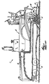
- a paver vehicle or “paver” 1 generally includes a paver chassis or tractor 2 and a screed 3 for leveling paving material and connected with the chassis 2 so as to be pulled from the rear end 2b thereof.
- a storage bin or hopper 4 for holding a supply of paving material P is typically mounted on the front end 2a of the chassis 2 and a conveyor 6, which extends longitudinally on the chassis 2, transports paving material P from the hopper 4 to the rear end 2b of the chassis 2.
- the material P falls off the chassis rear end 2b and deposits onto a base surface 7 being paved, such as a roadbed.
- An auger 8 is generally disposed between the rear end 2b of the chassis 2 and the screed 3 and functions to spread deposited material laterally across the front 3a of the screed 3 so as to form a head of material H.
- the screed 3 is pulled into the head of material H as the paver 1 travels upon the base surface 7 such that portions of the material head H flows under the screed 3 and is leveled, and preferably also compressed, into a mat of material M having a generally uniform thickness
- the paving material P such as asphalt or cement, is formed of an aggregate of material particles of various sizes and there are generally substantial size differences between the larger and smaller particles.
- US 5,232,305 discloses a prior art paving machine basically corresponding to the prior art paving machines described hereinabove comprising an antisegregation device consisting of a rigid plate with a flexible flap member.
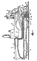
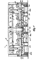
- the anti-segregation device 10 for preventing segregation of paving material P applied to a base surface 7 by a paver 1 having a screed 3.
- the anti-segregation device 10 basically comprises a barrier 12 having a first end 14 connectable with the paver 1, a second, opposing end 16 disposable against, or at least proximal to, the base surface 7 and a retentive surface 18 located between the first and second ends 14, 16 respectively.
- the retentive surface 18 faces generally toward the screed 3 when the first end 14 of the barrier 12 is connected with the paver 1 and is configured to substantially contain paving material P between the barrier 12 and the screed 3.
- the retentive surface 18 generally prevents particles of the paving material P from generally separating from the material head H, and in particular, substantially prevents larger material particles from falling, rolling or otherwise moving forwardly from the remainder of the material head H so as to generally prevent material segregation, such segregation being discussed above in the Background section hereof.
- the barrier 12 has a sufficient length such that the retentive surface 18 extends laterally across substantially the entire width W of the screed 3, as discussed below.
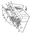
- the barrier 12 is constructed as a flexible curtain 22, the curtain 22 preferably including an elongated mounting bar 28 and a plurality of chains 20 spaced across generally the length of the bar 28.
- Each chain 20 has a first end 21 attached to the bar 28 and a second, free end 23 and is formed of a plurality of links 25 that each provide a separate surface portion of the retentive surface 18.
- the retentive surface 18 of the barrier 12 is provided by the total of all the individual link surfaces facing generally toward the screed 3.
- the individual chains 20 are spaced generally close together along the bar 28 so as to provide a more continuous retentive surface 18, as best shown in Figs. 6 and 7 .
- the curtain 22 may be constructed without the bar 28, with each of the plurality of chains 20 being separately and directly attached to a portion of the paver 1 (e.g., chassis rear wall 34).
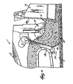
- each chain 20 has sufficient length such that a portion of the chain 20 at the lower chain end 23 is disposed upon the base surface 7 when the paver chassis 2 is generally horizontal on the base surface 7, as best shown in Figs. 6 and 7 .
- the lower chain ends 23, collectively forming the lower end 16 of the barrier 12 remain in contact with the base surface 7 to prevent particles of paving material from passing under the retentive surface 18.
- the lower end 16 of the barrier 12 is able to flex or bend against the base surface 7 without being damaged.
- the mounting bar 28 is connectable with a portion of the paver 1 so as to extend generally laterally in a direction across the width of the paver 1.
- the mounting bar 28 may be permanently affixed to a section of the paver 1, such as by welding, riveting, etc., or may be demountably attached thereto, such as by using threaded fasteners, clamps, etc.
- the barrier 12 is preferably constructed of a plurality of separate curtain sections 26, and most preferably five curtain sections 26a, 26b and 26c, each having a separate mounting bar 28 and a separate group of chains 20 and being arranged as follows.
- a first, central curtain section 26a ( Fig. 4 ) is attached to the lower end of the rear wall 34 of the paver chassis 2, two intermediate sections 26b are each attached to the lower end of a separate one of the two auger boxes 30 and the auger shields 31, and two outer curtain sections 26c ( Fig.
- the barrier 12 is collectively formed of the several curtain sections 26 and extends across substantially the entire width of the screed 3 of the paver 1, and therefore across the entire lateral-extending length of the head of material H.
- the barrier 12 may be formed of only a single flexible curtain 22, or may formed of any desired number of curtain sections 26.
- the auger 8 is disposed generally between the anti-segregation device 10 and the screed 3, thus containing the head of material H generally about the auger 8.
- the barrier 12 is attached to the rear wall 34 of the chassis 2, and if appropriate, to the screed end gates 27, so as the generally contain the head of material H between the barrier 12 and the screed 3.
- the flexible curtain 22 is preferably formed of a plurality of individual chains 20, the curtain 22 may alternatively be formed from other types of flexible strands, such as a plurality of wire cables (not shown), one or more sheets of a mesh-like material (not shown), such as for example a section(s) of "chicken wire” or a sheet(s) of cross-connected links, or from one or more sheets of a thin, bendable material (not shown).
- a plurality of wire cables not shown
- one or more sheets of a mesh-like material such as for example a section(s) of "chicken wire” or a sheet(s) of cross-connected links, or from one or more sheets of a thin, bendable material (not shown).
- the barrier 12 may even be formed of one or more generally rigid plates (not shown) having an upper end connected with the paver 1 and a lower end spaced above and proximal to the base surface 7.
- the barrier lower end 16 is unable to flex when contacting the base surface 7 and may become permanently deformed, or otherwise damaged, if the paver 1 tilts rearwardly during a paving operation.
- a paver 1 having an anti-segregation device 10 moves forwardly upon a base surface 7 such that the chassis 2 pulls the screed 3 into the head of material H and the mat M is formed thereby.
- the conveyor 6 continuously transports paving material P from the hopper 4 to deposit off of the chassis 3 to be distributed by the auger 8, such that the head of material H contains a generally consistent mass of material.
- the particles of the head of material H are imparted with momentum from being pushed by the forward moving screed 3, from contact with the rotating auger 8 and/or from being "flung" rearwardly off of the conveyor 6.
- the particles that move generally forwardly relative to the remainder of the head H impact against the retentive surface 18 of the barrier 12 and are thereby generally prevented from any further relative forward movement. Therefore, the larger particles of paving material are prevented from separating from the material head H, such that material segregation is substantially prevented by the anti-segregation device 10.
Landscapes
- Engineering & Computer Science (AREA)
- Architecture (AREA)
- Civil Engineering (AREA)
- Structural Engineering (AREA)
- Road Paving Machines (AREA)
Claims (14)
- Véhicule (1) de pavage permettant d'étendre un matériau de pavage sur un terrain de fondation, le véhicule (1) de pavage comprenant :un châssis (2) ayant une extrémité avant (2a) et une extrémité arrière (2b) ;une trémie (4) permettant de contenir une réserve de matériau de pavage, la trémie (4) étant montée sur l'extrémité avant (2a) du châssis (2);un convoyeur (6) qui s'étend de manière longitudinale sur le châssis (2) et transporte le matériau de pavage depuis la trémie (4) jusqu'à l'extrémité arrière (2b) du châssis (2) où le matériau de pavage tombe de l'extrémité arrière (2b) du châssis (2) sur le terrain de fondation;une règle (3) à araser permettant de niveler le matériau de pavage, la règle (3) à araser étant reliée au châssis (2) de façon à être tirée depuis l'extrémité arrière (2b) du châssis (2),caractérisé parun dispositif (10) anti-ségrégation positionné à proximité de la règle (3) à araser destiné à empêcher la ségrégation du matériau de pavage, qui est positionné sur le terrain de fondation devant la règle (3) à araser, le dispositif (10) anti-ségrégation comprenant un volet flexible (22) ayant une première extrémité (21) qui est fixée sur le châssis (2) du véhicule (1) de pavage et une deuxième extrémité (23) qui est située à proximité du terrain de fondation, le volet flexible (22) comprenant une barre (28) de montage allongée qui s'étend de manière latérale à travers le châssis (2) et plusieurs chaînes (20) situées à faible distance les unes des autres sur la longueur de la barre (28) de montage pour fournir une surface (18) de retenue continue du matériau de pavage.
- Véhicule (1) de pavage selon la revendication 1, dans lequel le volet flexible (22) peut être plié de manière séparée dans une position située à proximité du châssis (2) du véhicule et dans une position située à proximité du terrain de fondation.
- Utilisation d'un dispositif (10) comprenant : un volet flexible (22) ayant une première extrémité (21) reliée à un châssis (2) de véhicule de pavage, une deuxième extrémité (23) disposée à proximité d'une surface de base, et une surface (18) de retenue faisant généralement face à une règle (3) à araser du véhicule de pavage, la surface (18) de retenue retenant le matériau de pavage entre le volet (22) et la règle (3) à araser, le volet flexible (22) étant composé de plusieurs éléments flexibles allongés reliés à et espacés le long du châssis (2) du véhicule, chaque élément flexible étant une chaîne (20), en tant que dispositif (10) anti-ségrégation d'un véhicule (1) de pavage, permettant d'étendre le matériau de pavage sur une surface de base, le véhicule (1) de pavage comprenant le châssis (2) ayant une extrémité arrière (2b), la règle (3) à araser étant reliée au châssis (2) de façon à être tirée depuis l'extrémité arrière (2b) et une tarière (8) positionnée à l'avant de la règle (3) à araser et conçue pour étendre le matériau de pavage.
- Utilisation du dispositif (10) anti-ségrégation selon la revendication 3, dans lequel le volet flexible (22) s'étend de manière latérale à travers sensiblement toute la largeur de la règle (3) à araser.
- Utilisation du dispositif (10) anti-ségrégation selon la revendication 3, dans lequel le volet flexible (22) comprend une barre (28) de montage allongée reliée au châssis, les plusieurs chaînes (20) étant fixées et espacées sur la longueur de la barre (28) de montage.
- Utilisation du dispositif (10) anti-ségrégation selon la revendication 5, dans lequel la barre (28) de montage s'étend de manière latérale à travers le châssis du véhicule (1) de pavage.
- Utilisation du dispositif (10) anti-ségrégation selon la revendication 5, dans lequel chaque chaîne (20) comprend une extrémité (21) fixée sur la barre de montage et une extrémité libre opposée (23).
- Utilisation du dispositif (10) anti-ségrégation selon la revendication 7, dans lequel les chaînes (20) sont situées à faible distance les unes des autres le long de la barre de façon à fournir une surface de retenue continue pour le matériau de pavage (P).
- Utilisation du dispositif (10) anti-ségrégation selon la revendication 3, dans lequel chacune des chaînes (20) comprend une extrémité inférieure qui peut entrer en contact avec le terrain de fondation.
- Utilisation du dispositif anti-ségrégation selon la revendication 9, dans lequel les extrémités inférieures de la chaîne (20) restent en contact avec le terrain de fondation lorsque le véhicule (1) de pavage se déplace vers le haut pour passer au-dessus d'un obstacle.
- Utilisation du dispositif anti-ségrégation selon la revendication 9, dans lequel les chaînes (20) sont chacune adaptées pour se fléchir contre le terrain de fondation sans être endommagées.
- Utilisation du dispositif anti-ségrégation selon la revendication 9, dans lequel chaque chaîne comprend plusieurs maillons (25).
- Utilisation du dispositif (10) anti-ségrégation selon la revendication 3, dans lequel le volet comprend plusieurs sections de volets séparés, chacune des sections de volets étant montée sur le châssis à l'aide d'une barre de montage séparée.
- Utilisation du dispositif (10) anti-ségrégation selon la revendication 13, dans lequel les plusieurs sections de volets sont espacées de façon à s'étendre à travers sensiblement toute la largeur de la règle (3) à araser.
Applications Claiming Priority (2)
| Application Number | Priority Date | Filing Date | Title |
|---|---|---|---|
| US21898700P | 2000-07-17 | 2000-07-17 | |
| EP01933405A EP1313919B1 (fr) | 2000-07-17 | 2001-05-07 | Rideau pour finisseur empechant la segregation d'un materiau |
Related Parent Applications (2)
| Application Number | Title | Priority Date | Filing Date |
|---|---|---|---|
| EP01933405.1 Division | 2001-05-07 | ||
| EP01933405A Division EP1313919B1 (fr) | 2000-07-17 | 2001-05-07 | Rideau pour finisseur empechant la segregation d'un materiau |
Publications (2)
| Publication Number | Publication Date |
|---|---|
| EP2034093A1 EP2034093A1 (fr) | 2009-03-11 |
| EP2034093B1 true EP2034093B1 (fr) | 2012-05-30 |
Family
ID=22817315
Family Applications (2)
| Application Number | Title | Priority Date | Filing Date |
|---|---|---|---|
| EP08018413A Expired - Lifetime EP2034093B1 (fr) | 2000-07-17 | 2001-05-07 | Rideau anti-séparation de matériau pour une finisseuse |
| EP01933405A Expired - Lifetime EP1313919B1 (fr) | 2000-07-17 | 2001-05-07 | Rideau pour finisseur empechant la segregation d'un materiau |
Family Applications After (1)
| Application Number | Title | Priority Date | Filing Date |
|---|---|---|---|
| EP01933405A Expired - Lifetime EP1313919B1 (fr) | 2000-07-17 | 2001-05-07 | Rideau pour finisseur empechant la segregation d'un materiau |
Country Status (6)
| Country | Link |
|---|---|
| US (1) | US6802667B2 (fr) |
| EP (2) | EP2034093B1 (fr) |
| AU (1) | AU2001259835A1 (fr) |
| CA (1) | CA2415739C (fr) |
| DE (1) | DE60139325D1 (fr) |
| WO (1) | WO2002006589A1 (fr) |
Families Citing this family (4)
| Publication number | Priority date | Publication date | Assignee | Title |
|---|---|---|---|---|
| US8162565B2 (en) * | 2008-04-01 | 2012-04-24 | Volvo Construction Equipment Ab | Break-away material retainer for paving vehicles |
| US7785034B2 (en) * | 2008-06-26 | 2010-08-31 | Weiler, Inc. | Desegregation system |
| CN103526674B (zh) * | 2013-10-21 | 2015-11-04 | 戴纳派克(中国)压实摊铺设备有限公司 | 一种防离析螺旋分料器及摊铺机 |
| CN116334988B (zh) * | 2023-02-28 | 2023-10-13 | 徐工集团工程机械股份有限公司道路机械分公司 | 一种摊铺机分料系统及摊铺机 |
Family Cites Families (12)
| Publication number | Priority date | Publication date | Assignee | Title |
|---|---|---|---|---|
| US2032205A (en) * | 1931-06-09 | 1936-02-25 | Robert B Gage | Method of and apparatus for finishing concrete pavements |
| US3775018A (en) * | 1971-07-22 | 1973-11-27 | Cmi Corp | Road texturing machine |
| US3961493A (en) * | 1975-01-22 | 1976-06-08 | Brown & Root, Inc. | Methods and apparatus for purging liquid from an offshore pipeline and/or scanning a pipeline interior |
| CA1081516A (fr) * | 1975-12-31 | 1980-07-15 | Earl F. Cutler | Appareil pour renover les revetements en bitume |
| CA1184802A (fr) * | 1982-08-13 | 1985-04-02 | Joseph J. Matula | Epandeur de materiaux visqueux |
| US4708519A (en) * | 1986-04-04 | 1987-11-24 | White Consolidated Industries, Inc. | Asphalt paving machine with liftable, adjustable auger mechanisms |
| US4749304A (en) * | 1986-09-15 | 1988-06-07 | White Consolidated Industries, Inc. | Variable width material distribution system for asphalt pavers and the like |
| US4823366A (en) * | 1987-02-17 | 1989-04-18 | White Consolidated Industries, Inc. | Material conveying equipment with control for paving materials using ultrasonic waves |
| US5073063A (en) | 1990-08-20 | 1991-12-17 | White Consolidated Industries, Inc. | Windrow paving machine and method of paving |
| US5232305A (en) | 1991-05-15 | 1993-08-03 | Caterpillar Paving Products Inc. | Paving material distribution system |
| US5356238A (en) * | 1993-03-10 | 1994-10-18 | Cedarapids, Inc. | Paver with material supply and mat grade and slope quality control apparatus and method |
| US5533828A (en) * | 1994-09-29 | 1996-07-09 | Astec Industries, Inc. | Method and apparatus for discharging paving materials on top of distributing auger |
-
2001
- 2001-05-07 US US10/333,157 patent/US6802667B2/en not_active Expired - Lifetime
- 2001-05-07 WO PCT/US2001/040684 patent/WO2002006589A1/fr not_active Ceased
- 2001-05-07 EP EP08018413A patent/EP2034093B1/fr not_active Expired - Lifetime
- 2001-05-07 CA CA002415739A patent/CA2415739C/fr not_active Expired - Fee Related
- 2001-05-07 EP EP01933405A patent/EP1313919B1/fr not_active Expired - Lifetime
- 2001-05-07 AU AU2001259835A patent/AU2001259835A1/en not_active Abandoned
- 2001-05-07 DE DE60139325T patent/DE60139325D1/de not_active Expired - Lifetime
Also Published As
| Publication number | Publication date |
|---|---|
| EP1313919A1 (fr) | 2003-05-28 |
| US6802667B2 (en) | 2004-10-12 |
| AU2001259835A1 (en) | 2002-01-30 |
| EP1313919A4 (fr) | 2005-03-16 |
| CA2415739C (fr) | 2009-07-14 |
| CA2415739A1 (fr) | 2002-01-24 |
| EP1313919B1 (fr) | 2009-07-22 |
| EP2034093A1 (fr) | 2009-03-11 |
| WO2002006589A1 (fr) | 2002-01-24 |
| US20040042853A1 (en) | 2004-03-04 |
| DE60139325D1 (de) | 2009-09-03 |
Similar Documents
| Publication | Publication Date | Title |
|---|---|---|
| US5879104A (en) | Slip-form paver for road constructions of concrete | |
| JP3022991B2 (ja) | 舗装物質分配システム | |
| US7694805B2 (en) | Guard assembly and related methods | |
| US6481923B1 (en) | Concrete paving machine | |
| DE8903085U1 (de) | Selbstfahrendes Nutzfahrzeug für die Strandreinigung | |
| US5135333A (en) | Band reinforcement inserting apparatus and process | |
| CZ155194A3 (en) | Track sweeping machine | |
| US6283672B1 (en) | Pavement edger and joint maker | |
| EP2034093B1 (fr) | Rideau anti-séparation de matériau pour une finisseuse | |
| US5158394A (en) | Spreader device for particulate material | |
| US6238134B1 (en) | Pavement ramp and ramp making process | |
| US6238136B1 (en) | Paving machine and pavement edger therefor | |
| US5201127A (en) | Self metering ballast system | |
| CA2317868A1 (fr) | Systeme de distribution pour vehicule | |
| US6923594B2 (en) | Pavement ramp edge making | |
| US4878778A (en) | Concrete path paver | |
| US6270284B1 (en) | Pavement joint and joint making process | |
| US6988850B2 (en) | Pavement ramp edge making | |
| RU2106452C1 (ru) | Распределяющее устройство для дорожно-строительного материала | |
| US6884000B2 (en) | Material alignment for compaction | |
| WO2000061870A1 (fr) | Épandeur de matériaux | |
| JP4985988B2 (ja) | アスファルトフィニッシャにおけるレーン引きユニットの取付装置 | |
| US3732024A (en) | Leveler for paving machine | |
| DE29915875U1 (de) | Straßenfertiger | |
| JP2594711Y2 (ja) | 舗装体の締固装置 |
Legal Events
| Date | Code | Title | Description |
|---|---|---|---|
| PUAI | Public reference made under article 153(3) epc to a published international application that has entered the european phase |
Free format text: ORIGINAL CODE: 0009012 |
|
| 17P | Request for examination filed |
Effective date: 20081021 |
|
| AC | Divisional application: reference to earlier application |
Ref document number: 1313919 Country of ref document: EP Kind code of ref document: P |
|
| AK | Designated contracting states |
Kind code of ref document: A1 Designated state(s): AT BE CH CY DE DK ES FI FR GB GR IE IT LI LU MC NL PT SE TR |
|
| AX | Request for extension of the european patent |
Extension state: AL LT LV MK RO SI |
|
| 17Q | First examination report despatched |
Effective date: 20091009 |
|
| AKX | Designation fees paid |
Designated state(s): DE GB IT |
|
| GRAP | Despatch of communication of intention to grant a patent |
Free format text: ORIGINAL CODE: EPIDOSNIGR1 |
|
| GRAS | Grant fee paid |
Free format text: ORIGINAL CODE: EPIDOSNIGR3 |
|
| GRAA | (expected) grant |
Free format text: ORIGINAL CODE: 0009210 |
|
| AC | Divisional application: reference to earlier application |
Ref document number: 1313919 Country of ref document: EP Kind code of ref document: P |
|
| AK | Designated contracting states |
Kind code of ref document: B1 Designated state(s): DE GB IT |
|
| REG | Reference to a national code |
Ref country code: GB Ref legal event code: FG4D |
|
| REG | Reference to a national code |
Ref country code: DE Ref legal event code: R096 Ref document number: 60146649 Country of ref document: DE Effective date: 20120726 |
|
| PLBE | No opposition filed within time limit |
Free format text: ORIGINAL CODE: 0009261 |
|
| STAA | Information on the status of an ep patent application or granted ep patent |
Free format text: STATUS: NO OPPOSITION FILED WITHIN TIME LIMIT |
|
| 26N | No opposition filed |
Effective date: 20130301 |
|
| REG | Reference to a national code |
Ref country code: DE Ref legal event code: R097 Ref document number: 60146649 Country of ref document: DE Effective date: 20130301 |
|
| PGFP | Annual fee paid to national office [announced via postgrant information from national office to epo] |
Ref country code: DE Payment date: 20160518 Year of fee payment: 16 Ref country code: GB Payment date: 20160523 Year of fee payment: 16 |
|
| PGFP | Annual fee paid to national office [announced via postgrant information from national office to epo] |
Ref country code: IT Payment date: 20160509 Year of fee payment: 16 |
|
| REG | Reference to a national code |
Ref country code: DE Ref legal event code: R119 Ref document number: 60146649 Country of ref document: DE |
|
| GBPC | Gb: european patent ceased through non-payment of renewal fee |
Effective date: 20170507 |
|
| PG25 | Lapsed in a contracting state [announced via postgrant information from national office to epo] |
Ref country code: GB Free format text: LAPSE BECAUSE OF NON-PAYMENT OF DUE FEES Effective date: 20170507 Ref country code: DE Free format text: LAPSE BECAUSE OF NON-PAYMENT OF DUE FEES Effective date: 20171201 |
|
| PG25 | Lapsed in a contracting state [announced via postgrant information from national office to epo] |
Ref country code: IT Free format text: LAPSE BECAUSE OF NON-PAYMENT OF DUE FEES Effective date: 20170507 |