EP2034178B1 - Windturbinenschaufel mit lenkbaren Blättern - Google Patents
Windturbinenschaufel mit lenkbaren Blättern Download PDFInfo
- Publication number
- EP2034178B1 EP2034178B1 EP08010999.4A EP08010999A EP2034178B1 EP 2034178 B1 EP2034178 B1 EP 2034178B1 EP 08010999 A EP08010999 A EP 08010999A EP 2034178 B1 EP2034178 B1 EP 2034178B1
- Authority
- EP
- European Patent Office
- Prior art keywords
- flap
- blade
- wind turbine
- turbine according
- component
- Prior art date
- Legal status (The legal status is an assumption and is not a legal conclusion. Google has not performed a legal analysis and makes no representation as to the accuracy of the status listed.)
- Active
Links
Images
Classifications
-
- F—MECHANICAL ENGINEERING; LIGHTING; HEATING; WEAPONS; BLASTING
- F03—MACHINES OR ENGINES FOR LIQUIDS; WIND, SPRING, OR WEIGHT MOTORS; PRODUCING MECHANICAL POWER OR A REACTIVE PROPULSIVE THRUST, NOT OTHERWISE PROVIDED FOR
- F03D—WIND MOTORS
- F03D1/00—Wind motors with rotation axis substantially parallel to the air flow entering the rotor
- F03D1/06—Rotors
- F03D1/0608—Rotors characterised by their aerodynamic shape
-
- F—MECHANICAL ENGINEERING; LIGHTING; HEATING; WEAPONS; BLASTING
- F03—MACHINES OR ENGINES FOR LIQUIDS; WIND, SPRING, OR WEIGHT MOTORS; PRODUCING MECHANICAL POWER OR A REACTIVE PROPULSIVE THRUST, NOT OTHERWISE PROVIDED FOR
- F03D—WIND MOTORS
- F03D7/00—Controlling wind motors
- F03D7/02—Controlling wind motors the wind motors having rotation axis substantially parallel to the air flow entering the rotor
- F03D7/0256—Stall control
-
- F—MECHANICAL ENGINEERING; LIGHTING; HEATING; WEAPONS; BLASTING
- F03—MACHINES OR ENGINES FOR LIQUIDS; WIND, SPRING, OR WEIGHT MOTORS; PRODUCING MECHANICAL POWER OR A REACTIVE PROPULSIVE THRUST, NOT OTHERWISE PROVIDED FOR
- F03D—WIND MOTORS
- F03D1/00—Wind motors with rotation axis substantially parallel to the air flow entering the rotor
- F03D1/06—Rotors
- F03D1/065—Rotors characterised by their construction elements
- F03D1/0675—Rotors characterised by their construction elements of the blades
-
- F—MECHANICAL ENGINEERING; LIGHTING; HEATING; WEAPONS; BLASTING
- F03—MACHINES OR ENGINES FOR LIQUIDS; WIND, SPRING, OR WEIGHT MOTORS; PRODUCING MECHANICAL POWER OR A REACTIVE PROPULSIVE THRUST, NOT OTHERWISE PROVIDED FOR
- F03D—WIND MOTORS
- F03D7/00—Controlling wind motors
- F03D7/02—Controlling wind motors the wind motors having rotation axis substantially parallel to the air flow entering the rotor
- F03D7/022—Adjusting aerodynamic properties of the blades
- F03D7/0224—Adjusting blade pitch
-
- F—MECHANICAL ENGINEERING; LIGHTING; HEATING; WEAPONS; BLASTING
- F03—MACHINES OR ENGINES FOR LIQUIDS; WIND, SPRING, OR WEIGHT MOTORS; PRODUCING MECHANICAL POWER OR A REACTIVE PROPULSIVE THRUST, NOT OTHERWISE PROVIDED FOR
- F03D—WIND MOTORS
- F03D7/00—Controlling wind motors
- F03D7/02—Controlling wind motors the wind motors having rotation axis substantially parallel to the air flow entering the rotor
- F03D7/022—Adjusting aerodynamic properties of the blades
- F03D7/0232—Adjusting aerodynamic properties of the blades with flaps or slats
-
- F—MECHANICAL ENGINEERING; LIGHTING; HEATING; WEAPONS; BLASTING
- F03—MACHINES OR ENGINES FOR LIQUIDS; WIND, SPRING, OR WEIGHT MOTORS; PRODUCING MECHANICAL POWER OR A REACTIVE PROPULSIVE THRUST, NOT OTHERWISE PROVIDED FOR
- F03D—WIND MOTORS
- F03D7/00—Controlling wind motors
- F03D7/02—Controlling wind motors the wind motors having rotation axis substantially parallel to the air flow entering the rotor
- F03D7/0244—Controlling wind motors the wind motors having rotation axis substantially parallel to the air flow entering the rotor for braking
- F03D7/0252—Controlling wind motors the wind motors having rotation axis substantially parallel to the air flow entering the rotor for braking with aerodynamic drag devices on the blades
-
- F—MECHANICAL ENGINEERING; LIGHTING; HEATING; WEAPONS; BLASTING
- F05—INDEXING SCHEMES RELATING TO ENGINES OR PUMPS IN VARIOUS SUBCLASSES OF CLASSES F01-F04
- F05B—INDEXING SCHEME RELATING TO WIND, SPRING, WEIGHT, INERTIA OR LIKE MOTORS, TO MACHINES OR ENGINES FOR LIQUIDS COVERED BY SUBCLASSES F03B, F03D AND F03G
- F05B2240/00—Components
- F05B2240/20—Rotors
- F05B2240/30—Characteristics of rotor blades, i.e. of any element transforming dynamic fluid energy to or from rotational energy and being attached to a rotor
- F05B2240/305—Flaps, slats or spoilers
- F05B2240/3052—Flaps, slats or spoilers adjustable
-
- F—MECHANICAL ENGINEERING; LIGHTING; HEATING; WEAPONS; BLASTING
- F05—INDEXING SCHEMES RELATING TO ENGINES OR PUMPS IN VARIOUS SUBCLASSES OF CLASSES F01-F04
- F05B—INDEXING SCHEME RELATING TO WIND, SPRING, WEIGHT, INERTIA OR LIKE MOTORS, TO MACHINES OR ENGINES FOR LIQUIDS COVERED BY SUBCLASSES F03B, F03D AND F03G
- F05B2240/00—Components
- F05B2240/20—Rotors
- F05B2240/30—Characteristics of rotor blades, i.e. of any element transforming dynamic fluid energy to or from rotational energy and being attached to a rotor
- F05B2240/31—Characteristics of rotor blades, i.e. of any element transforming dynamic fluid energy to or from rotational energy and being attached to a rotor of changeable form or shape
-
- F—MECHANICAL ENGINEERING; LIGHTING; HEATING; WEAPONS; BLASTING
- F05—INDEXING SCHEMES RELATING TO ENGINES OR PUMPS IN VARIOUS SUBCLASSES OF CLASSES F01-F04
- F05B—INDEXING SCHEME RELATING TO WIND, SPRING, WEIGHT, INERTIA OR LIKE MOTORS, TO MACHINES OR ENGINES FOR LIQUIDS COVERED BY SUBCLASSES F03B, F03D AND F03G
- F05B2240/00—Components
- F05B2240/20—Rotors
- F05B2240/30—Characteristics of rotor blades, i.e. of any element transforming dynamic fluid energy to or from rotational energy and being attached to a rotor
- F05B2240/31—Characteristics of rotor blades, i.e. of any element transforming dynamic fluid energy to or from rotational energy and being attached to a rotor of changeable form or shape
- F05B2240/311—Characteristics of rotor blades, i.e. of any element transforming dynamic fluid energy to or from rotational energy and being attached to a rotor of changeable form or shape flexible or elastic
-
- Y—GENERAL TAGGING OF NEW TECHNOLOGICAL DEVELOPMENTS; GENERAL TAGGING OF CROSS-SECTIONAL TECHNOLOGIES SPANNING OVER SEVERAL SECTIONS OF THE IPC; TECHNICAL SUBJECTS COVERED BY FORMER USPC CROSS-REFERENCE ART COLLECTIONS [XRACs] AND DIGESTS
- Y02—TECHNOLOGIES OR APPLICATIONS FOR MITIGATION OR ADAPTATION AGAINST CLIMATE CHANGE
- Y02E—REDUCTION OF GREENHOUSE GAS [GHG] EMISSIONS, RELATED TO ENERGY GENERATION, TRANSMISSION OR DISTRIBUTION
- Y02E10/00—Energy generation through renewable energy sources
- Y02E10/70—Wind energy
- Y02E10/72—Wind turbines with rotation axis in wind direction
Definitions
- the invention relates to a wind turbine having rotor blades with deflectable flaps and in particular to rotor blades with deflectable flaps for optimizing the blade loads.
- Wind turbines are devices that convert mechanical energy to electrical energy.
- a typical wind turbine includes a nacelle mounted on a tower housing a drive train for transmitting the rotation of a rotor to an electric generator.
- the efficiency of a wind turbine depends on many factors. One of them is the orientation of the rotor blades with respect to the direction of the air stream, which is usually controlled by a pitch system that allows adjusting the pitch angle of the rotor blades for maintaining the rotor's speed at a constant value or within a given range. Otherwise, specially at high wind speeds, the load of the rotor will exceed the limits set by the wind turbine's structural strength.
- the rotor blade's pitch angle is changed to a smaller angle of attack in order to reduce power capture and to a greater angle of attack to increase the power capture. This method allows a sensitive and stable control of the aerodynamic power capture and rotor speed.
- the pitch regulated wind turbines can also use the pitch system to reduce the dynamic loads, either by cyclic pitch or by individual blade pitch.
- pitch system can also use the pitch system to reduce the dynamic loads, either by cyclic pitch or by individual blade pitch.
- the pitching of the blades not necessarily provides an optimized loading along the whole blade because nor only wind shear, yaw errors and gust will affect the flow on the blade, but different gusts can hit the blade simultaneously or complex wind shear profiles with negative wind shear can occur.
- Gurney flaps attached to the trailing edge for optimizing the blade loads.
- One disadvantage of Gurney flaps is the increase in aerodynamic noise from the free ends of the Gurney flaps and from the gaps in the blade where the Gurney flaps are positioned.
- piezoelectric plates are to built in the trailing edge over part of the blade for modifying its geometry in order to reduce the blade loads.
- One disadvantage of the piezoelectric plates are the electrical cables that are necessary to bring power to them. These cables are woundable to electrical lightning and can easily be damaged in case of a lightning strike.
- EP1375911 discloses a power-generating propeller-style wind turbine provided with a plurality of turbines blades characterized in that a blade body of each turbine blade includes therewithin a tip auxiliary blade housed to be capable of extending toward and retracting away from a blade tip, and an auxiliary blade extension-and-retraction unit for protruding the tip auxiliary blade toward the blade tip so as to increase an overall length of the blade.
- An object of the invention is to provide a wind turbine that, in addition to a pitch system, has special means for achieving an accurate control of the blade loads.
- Another object of the invention is to provide a wind turbine having means for controlling the changes in the flow and hence optimizing the whole rotor performance and minimizing the pitch activity of the blades.
- a wind turbine with rotor blades comprising a first component having an aerodynamic profile with a leading edge, a trailing edge and suction and pressure sides between the leading edge and the trailing edge and a second component, attached to the trailing edge and/or to the leading edge of the first component in at least a part of the blade, which comprises an upwards and/or downwards deflectable flap by means of fluid inflatable means placed in a flap inner chamber close to the first component that allows changing the flow over the blade, and means for controlling the deflection of said flap for optimizing the blade loads depending on the wind situation and/or the blade loads.
- the flap deflection is controlled by load measurements on the blade, velocity or pressure measurements of the air on the blade or lidar measurements of the flow in front of the blade. With the load feed back and the appropriate control algorithm the flap can be used to control the blade loading more accurate than in the prior art.
- said fluid inflatable means is a flexible tube extending along the flap spanwise direction which is arranged inside a chamber deflecting the flap upwards.
- a deflectable flap in one direction upwards or downwards it is achieved.
- said fluid inflatable means are two flexible tubes extending along the flap spanwise direction and arranged inside a chambers placed in suitable position for deflecting the flap in both directions.
- a deflectable flap in both directions upwards and downwards it is achieved.
- the second component also includes a lower and/or upper fairing plate for preventing air gaps when the flap is deflected.
- a lower and/or upper fairing plate for preventing air gaps when the flap is deflected.
- the flap can be made in one piece of a flexible material, such as rubber or pultruded fiberglass.
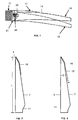
- Figure 1 shows the second component 13 attached to the first component 11 of a wind turbine blade according to a first embodiment of the present invention.
- the first component 11 has a typical aerodynamic profile with a leading edge 5, a trailing edge 7 and suction and pressure sides between the leading edge 5 and the trailing edge 7.
- the second component 13 includes a deflectable flap 15 and a fairing plate 17.
- Figure 1 illustrates a downwards deflection of flap 15 from a first position to a second position -in phantom lines- by means of the inflation of a rubber tube 23 located in an inner chamber 25 with air or any other suitable fluid.
- the fairing plate 17 covers the flap 15 avoiding any air gap during its deflection.
- the flap 15 is made in one piece of a flexible material and it is attached to the first component 11 with glue, bolts or any other suitable means.
- the flap 15 may be made integrating the tube 23 in a full rubber flap which will hence be one piece with everything integrated in.
- Another preferred solution is to make the flap 15 and the fairing plate 17 as a pulltruded profile eg. in glass fiber reinforced composite material.
- the attachment to the first component 11 will be flexible due to the geometrical shape and the mechanical properties of the material and the rubber tube 23 can be hidden inside the flap 15 and hence protected for UV radiation, ice etc.
- Figure 1 shows the deflection of flap 15 from an first neutral position to a second downwards position but the invention also comprises a flap 15 configured for deflecting from a first upwards position to a second downwards position or vice versa.
- the neutral position will require a certain pressure inside the tube 23.
- the flap 15 includes two inflatable tubes 23 for having a sort of double hinge system, one at the upper part and one on the lower part for a better control of direction of its deflection.
- the advantage of this solution is that in case of mal-function of the system, i.e. no pressure on the inflatable tubes, the flap 15 will be in neutral position and hence the wind turbine can operate as a normal pitch controlled wind turbine, until the system has been repaired.
- the blade may include one individual flap 15 as shown in Figure 2 or several flaps 15, 15' as shown in Fig. 3 . In the latter case each flap 15, 15' has its own inflatable means 23.
- the width W of the flap or flaps 15, 15' is comprised between 1-20% of the chord length C in the center of the flap.
- the width W of the flap or flaps 15, 15' may be constant or variable. In the first case the width will be usually smaller close to the tip region and larger towards the root section of the blade. In the latter case, the width W of the flap 15', as shown in Fig. 3 will decrease towards the tip of the blade.
- the flap or flaps 15, 15' are attached to the blade leading edge 5 and/or to the blade trailing edge 7 in a section having a length lesser than 1/3 of the blade length L.
- flaps 15 are be mounted in sections of the blade, they will be designed in a manner that could be replaceable and could be mounted with few screws.
- the air/liquid connection could be a snap connection and hereby the modularity of this unit is high, and hence easy to change during maintenance.
- a rubber plate could be mounted between them and hereby avoiding air to flow in the air gap, which could generate whistle tones.
- the wind turbine comprises computer means for controlling the actuating means 23 that deflect the flap 15 taking into account load measurements on the blade and relevant airflow parameters provided by sensors.
Landscapes
- Engineering & Computer Science (AREA)
- Life Sciences & Earth Sciences (AREA)
- Sustainable Development (AREA)
- Sustainable Energy (AREA)
- Chemical & Material Sciences (AREA)
- Combustion & Propulsion (AREA)
- Mechanical Engineering (AREA)
- General Engineering & Computer Science (AREA)
- Physics & Mathematics (AREA)
- Fluid Mechanics (AREA)
- Wind Motors (AREA)
Claims (10)
- - Eine Windenergieanlage, deren Rotorblätter zumindest aus einem ersten Bauteil (11) bestehen, das ein aerodynamisches Profil besitzt mit einer Vorderkante, einer Hinterkante sowie einer Saug- und Druckseite zwischen der Vorder- und der Hinterkante und einem zweiten Bauteil (13), das zumindest in einem Teilbereich des Rotorblatts an der Hinter- und/oder Vorderkante des ersten Bauteils (11) befestigt ist, wobei:- das zweite Bauteil (13) über eine nach oben und/oder unten auslenkbare Klappe (15) verfügt, die eine Änderung des Luftstroms über das Rotorblatt ermöglicht;- die auslenkbare Klappe (15) durch eine mit Flüssigkeit füllbare Vorrichtung (23) ausgelenkt wird, die in einer inneren Kammer (25) der Klappe nahe des ersten Bauteils (11) untergebracht ist;- die Windenergieanlage über eine Vorrichtung zur Ansteuerung der besagten mit Flüssigkeit füllbaren Vorrichtung (23) je nach Windsituation und/oder Belastung der Rotorblätter verfügt; undsich dadurch auszeichnet, dass es sich bei der mit Flüssigkeit füllbaren Vorrichtung um eine flexible Leitung (23) handelt, die entlang der Klappe (15) in Spannweitenrichtung verläuft oder
es sich bei der mit Flüssigkeit füllbaren Vorrichtung um zwei flexible Leitungen (23) handelt, die entlang der Klappe (15) in Spannweitenrichtung verlaufen, wobei eine der beiden flexiblen Leitungen zum Auslenken der Klappe (15) nach oben konfiguriert ist, die andere flexible Leitung zum Auslenken der Klappe (15) nach unten. - - Eine Windenergieanlage gemäß Anspruch 1, die sich dadurch auszeichnet, dass das zweite Bauteil (13) zudem über eine untere und/oder obere Schürzenplatte (17) verfügt, die das Entstehen eines Luftspalts bei ausgelenkter Klappe (15) verhindert.
- - Eine Windenergieanlage gemäß Anspruch 1 und 2, die sich dadurch auszeichnet, dass die Klappe (15) in einem Stück aus einem flexiblen Material hergestellt wird.
- - Eine Windenergieanlage gemäß Anspruch 3, die sich dadurch auszeichnet, dass die Klappe (15) aus Gummi besteht.
- - Eine Windenergieanlage gemäß Anspruch 4, die sich dadurch auszeichnet, dass die Klappe (15) aus einem im Strangziehverfahren gefertigten glasfaserverstärkten Verbundwerkstoff besteht
- - Eine Windenergieanlage gemäß den Ansprüchen 1-5, die sich dadurch auszeichnet, dass eine Breite W der Klappe (15) zwischen 1 und 20 % einer Sehnenlänge C des Rotorblatts in der Mitte der Klappe (15) ausmacht.
- - Eine Windenergieanlage gemäß Anspruch 6, die sich dadurch auszeichnet, dass die Breite W der Klappe (15) über die Länge der Klappe konstant ist.
- - Eine Windenergieanlage gemäß Anspruch 7, die sich dadurch auszeichnet, dass die Breite W der Klappe (15') über die Länge der Klappe variabel ist.
- - Eine Windenergieanlage gemäß einem beliebigen der Ansprüche 1-8, die sich dadurch auszeichnet, dass die Klappe (15) an der Vorderkante (5) des Rotorblatts und/oder der Hinterkante (7) des Rotorblatts in einem Abschnitt angebracht ist, der weniger als 1/3 der Länge L des Rotorblatts ausmacht.
- - Eine Windenergieanlage gemäß einem beliebigen der Ansprüche 1-8, die sich dadurch auszeichnet, dass die Rotorblätter mit einem oder mehreren zweiten Bauteilen (13) ausgestattet sind, von denen jedes eine eigene Klappe (15, 15') mit individueller flüssigkeitsfüllbarer Vorrichtung (23) besitzt.
Priority Applications (1)
| Application Number | Priority Date | Filing Date | Title |
|---|---|---|---|
| PL08010999T PL2034178T3 (pl) | 2007-06-22 | 2008-06-18 | Łopata turbiny wiatrowej z odchylanymi klapami |
Applications Claiming Priority (1)
| Application Number | Priority Date | Filing Date | Title |
|---|---|---|---|
| ES200701738A ES2324002B1 (es) | 2007-06-22 | 2007-06-22 | Pala de aerogenerador con alerones deflectables. |
Publications (3)
| Publication Number | Publication Date |
|---|---|
| EP2034178A2 EP2034178A2 (de) | 2009-03-11 |
| EP2034178A3 EP2034178A3 (de) | 2016-08-03 |
| EP2034178B1 true EP2034178B1 (de) | 2017-08-23 |
Family
ID=39823810
Family Applications (1)
| Application Number | Title | Priority Date | Filing Date |
|---|---|---|---|
| EP08010999.4A Active EP2034178B1 (de) | 2007-06-22 | 2008-06-18 | Windturbinenschaufel mit lenkbaren Blättern |
Country Status (5)
| Country | Link |
|---|---|
| US (1) | US8087889B2 (de) |
| EP (1) | EP2034178B1 (de) |
| CN (1) | CN101338727B (de) |
| ES (2) | ES2324002B1 (de) |
| PL (1) | PL2034178T3 (de) |
Families Citing this family (42)
| Publication number | Priority date | Publication date | Assignee | Title |
|---|---|---|---|---|
| US9039372B2 (en) * | 2007-04-30 | 2015-05-26 | Vestas Wind Systems A/S | Wind turbine blade |
| WO2008131800A1 (en) * | 2007-04-30 | 2008-11-06 | Vestas Wind Systems A/S | A wind turbine blade |
| EP2350452B2 (de) * | 2008-10-14 | 2020-08-19 | Vestas Wind Systems A/S | Windturbinenblatt mit einer Vorrichtung zur Änderung der aerodynamischen Fläche oder Form |
| GB2465975B (en) * | 2008-12-02 | 2010-10-13 | Vestas Wind Sys As | Wind turbine control surface hinge |
| GB2466200A (en) * | 2008-12-10 | 2010-06-16 | Vestas Wind Sys As | A Detection System of an Angle of Attack of Air Flow over a Wind Turbine Rotor Blade |
| US8186936B2 (en) * | 2009-06-08 | 2012-05-29 | Vestas Wind Systems A/S | Actuation of movable parts of a wind turbine rotor blade |
| DE102009060082A1 (de) * | 2009-12-22 | 2011-06-30 | Airbus Operations GmbH, 21129 | Flügelanordnung mit einer verstellbaren Klappe und Verkleidungselement zum Verkleiden eines Klappenverstellmechanismus eines Flügels |
| KR101068443B1 (ko) * | 2009-12-24 | 2011-09-28 | 황지선 | 풍력 발전용 로터 |
| US10137542B2 (en) | 2010-01-14 | 2018-11-27 | Senvion Gmbh | Wind turbine rotor blade components and machine for making same |
| MX341495B (es) | 2010-01-14 | 2016-08-23 | Neptco Inc * | Componentes de pala de rotor de turbina eolica y metodos para la fabricacion de los mismos. |
| US9353728B2 (en) * | 2010-05-10 | 2016-05-31 | Technische Universität Darmstadt | Invention relating to rotor blades, in particular for wind power installations |
| PL2405129T3 (pl) * | 2010-07-06 | 2017-06-30 | Lm Wp Patent Holding A/S | Łopata turbiny wiatrowej o zmiennej krawędzi spływu |
| US9774198B2 (en) * | 2010-11-08 | 2017-09-26 | Brandon Culver | Wind and solar powered heat trace with homeostatic control |
| US20110142676A1 (en) * | 2010-11-16 | 2011-06-16 | General Electric Company | Rotor blade assembly having an auxiliary blade |
| US20120020803A1 (en) * | 2011-02-14 | 2012-01-26 | Paul Lees | Turbine blades, systems and methods |
| EP2712401B1 (de) * | 2011-04-28 | 2016-10-05 | Vestas Wind Systems A/S | Verbesserte verfahren zur windturbinengeräuschkontrolle |
| DK177278B1 (en) * | 2011-05-19 | 2012-09-17 | Envision Energy Denmark Aps | A wind turbine and associated control method |
| DK178073B1 (en) * | 2011-06-17 | 2015-04-27 | Envision Energy Denmark Aps | A Wind Turbine Blade |
| US9133819B2 (en) | 2011-07-18 | 2015-09-15 | Kohana Technologies Inc. | Turbine blades and systems with forward blowing slots |
| US8834127B2 (en) * | 2011-09-09 | 2014-09-16 | General Electric Company | Extension for rotor blade in wind turbine |
| WO2013045601A1 (en) * | 2011-09-29 | 2013-04-04 | Lm Wind Power A/S | A wind turbine blade |
| US8506248B2 (en) | 2011-10-06 | 2013-08-13 | General Electric Company | Wind turbine rotor blade with passively modified trailing edge component |
| US8602732B2 (en) | 2011-10-06 | 2013-12-10 | General Electric Company | Wind turbine rotor blade with passively modified trailing edge component |
| DE102012209935A1 (de) * | 2011-12-08 | 2013-06-13 | Wobben Properties Gmbh | Hinterkasten, Rotorblatt mit Hinterkasten und Windenergieanlage mit solchem Rotorblatt |
| EP2631467B1 (de) | 2012-02-24 | 2015-10-14 | Siemens Aktiengesellschaft | Anordnung zur Minderung der von einer Windturbinenschaufel erzeugten Geräusche |
| ES2609240T3 (es) | 2012-04-04 | 2017-04-19 | Siemens Aktiengesellschaft | Disposición de aleta flexible para una pala de rotor de turbina eólica |
| US9919488B2 (en) * | 2014-03-19 | 2018-03-20 | General Electric Company | Rotor blade components for a wind turbine and methods of manufacturing same |
| GB2537630B (en) * | 2015-04-21 | 2020-11-04 | Agustawestland Ltd | An aerofoil |
| CN104989591A (zh) * | 2015-06-30 | 2015-10-21 | 上海理工大学 | 扑翼可调式叶片 |
| DK3290688T3 (da) * | 2016-08-30 | 2021-02-01 | Siemens Gamesa Renewable Energy As | Regulering af rotationshastighed ved ændring af vingeprofil |
| US10612517B2 (en) * | 2017-03-09 | 2020-04-07 | General Electric Company | Flexible extension for wind turbine rotor blades |
| CN111315653A (zh) * | 2017-11-06 | 2020-06-19 | 菲利普·博格拉什 | 可在每次旋转中动态优化形状及其它属性的旋翼或推进器叶片 |
| DE102018100963A1 (de) * | 2018-01-17 | 2019-07-18 | Wobben Properties Gmbh | Windenergieanlage und Rotorblatt für eine Windenergieanlage |
| EP3517773B1 (de) * | 2018-01-29 | 2020-08-12 | Siemens Gamesa Renewable Energy A/S | Hinterkantenanordnung |
| EP3788252A4 (de) * | 2018-05-04 | 2022-05-25 | General Electric Company | Flexible verlängerung für windturbinenrotorblätter |
| CN110792554B (zh) * | 2018-08-03 | 2020-12-11 | 兰州理工大学 | 变形式风力发电机叶片 |
| EP3667076A1 (de) * | 2018-12-13 | 2020-06-17 | Siemens Gamesa Renewable Energy A/S | Schätzung der windgeschwindigkeit |
| DE102019117365A1 (de) * | 2019-06-27 | 2020-12-31 | Wobben Properties Gmbh | Rotor für eine Windenergieanlage, Windenergieanlage und zugehöriges Verfahren |
| CN110562442B (zh) * | 2019-08-29 | 2022-11-22 | 中国航空工业集团公司沈阳飞机设计研究所 | 一种采用半柔性驱动控制的襟翼装置 |
| CN115126649A (zh) * | 2022-05-30 | 2022-09-30 | 南方海洋科学与工程广东省实验室(广州) | 一种低噪风力发电机叶片 |
| CN116480513A (zh) * | 2023-05-17 | 2023-07-25 | 中国长江三峡集团有限公司 | 一种叶片及潮流能发电机 |
| CN119664569B (zh) * | 2024-12-20 | 2025-11-18 | 西华大学 | 一种柔性振动自适应风力机叶片 |
Family Cites Families (19)
| Publication number | Priority date | Publication date | Assignee | Title |
|---|---|---|---|---|
| US2753835A (en) * | 1952-04-03 | 1956-07-10 | Gehrig Walter | Angle of attack governed aircraft apparatus |
| US5320491A (en) * | 1992-07-09 | 1994-06-14 | Northern Power Systems, Inc. | Wind turbine rotor aileron |
| US5375324A (en) * | 1993-07-12 | 1994-12-27 | Flowind Corporation | Vertical axis wind turbine with pultruded blades |
| DK172932B1 (da) * | 1995-06-27 | 1999-10-11 | Bonus Energy As | Fremgangsmåde og indretning til reduktion af svingninger i en vindmøllevinge. |
| DE19544805C1 (de) * | 1995-12-01 | 1997-06-12 | Daimler Benz Aerospace Ag | Elektrochemisches Stellelement |
| JPH11512998A (ja) * | 1996-07-18 | 1999-11-09 | プロスペクテイブ コンセプツ アクチエンゲゼルシヤフト | 固定翼航空機用空気入り適応翼 |
| US6015115A (en) * | 1998-03-25 | 2000-01-18 | Lockheed Martin Corporation | Inflatable structures to control aircraft |
| WO1999061313A1 (de) * | 1998-05-25 | 1999-12-02 | Prospective Concepts Ag | Adaptiver pneumatischer flügel für starrflügel-fluggeräte |
| DE10061636B4 (de) * | 2000-12-11 | 2010-02-04 | Eurocopter Deutschland Gmbh | Rotorblatt mit Klappe und Klappenantrieb |
| ES2397263T3 (es) * | 2000-12-23 | 2013-03-05 | Aloys Wobben | Pala de rotor para una instalación de energía eólica |
| EP1375911A4 (de) * | 2001-03-26 | 2005-11-23 | Hitachi Shipbuilding Eng Co | Windturbine vom propellertyp |
| DE10233102B4 (de) * | 2002-06-21 | 2006-02-16 | Intema Industrietextilverarbeitung Gmbh | Rotorblatt für Windkraftanlagen |
| US6769873B2 (en) | 2002-10-08 | 2004-08-03 | The United States Of America As Represented By The Secretary Of The Navy | Dynamically reconfigurable wind turbine blade assembly |
| EP1613860B1 (de) * | 2003-03-31 | 2015-11-04 | Technical University of Denmark | Regelung der leistung, der last, und/oder der stabilität in einer windkraftanlage mit waagerechter welle durch variieren der geometrie der blätter |
| DK200300670A (da) * | 2003-05-05 | 2004-11-06 | Lm Glasfiber As | Vindmölleving med opdriftsregulerende organer |
| DE10348060B4 (de) * | 2003-10-16 | 2016-10-27 | Windreich GmbH | Rotorblatt eines Rotors einer Windenergieanlage |
| FR2864175B1 (fr) * | 2003-12-22 | 2008-03-28 | Airbus | Eolienne |
| US8157533B2 (en) * | 2005-10-17 | 2012-04-17 | Vestas Wind Systems A/S | Wind turbine blade with variable aerodynamic profile |
| EP1995455B1 (de) * | 2007-05-25 | 2016-11-16 | Siemens Aktiengesellschaft | Antriebssystem für eine Klappe eines Rotorblattes einer Windenergieanlage |
-
2007
- 2007-06-22 ES ES200701738A patent/ES2324002B1/es not_active Expired - Fee Related
-
2008
- 2008-06-16 US US12/214,074 patent/US8087889B2/en active Active
- 2008-06-18 ES ES08010999.4T patent/ES2648818T3/es active Active
- 2008-06-18 PL PL08010999T patent/PL2034178T3/pl unknown
- 2008-06-18 EP EP08010999.4A patent/EP2034178B1/de active Active
- 2008-06-23 CN CN2008101314941A patent/CN101338727B/zh active Active
Non-Patent Citations (1)
| Title |
|---|
| None * |
Also Published As
| Publication number | Publication date |
|---|---|
| CN101338727A (zh) | 2009-01-07 |
| US20090028705A1 (en) | 2009-01-29 |
| ES2648818T3 (es) | 2018-01-08 |
| PL2034178T3 (pl) | 2018-01-31 |
| US8087889B2 (en) | 2012-01-03 |
| CN101338727B (zh) | 2013-03-27 |
| EP2034178A3 (de) | 2016-08-03 |
| ES2324002A1 (es) | 2009-07-28 |
| EP2034178A2 (de) | 2009-03-11 |
| ES2324002B1 (es) | 2010-05-13 |
Similar Documents
| Publication | Publication Date | Title |
|---|---|---|
| EP2034178B1 (de) | Windturbinenschaufel mit lenkbaren Blättern | |
| EP2019203B2 (de) | Rotorblatt einer Windenergieanlage mit gewölbten Klappen | |
| EP2085609B1 (de) | Windturbinenschaufel mit Biegklappen, die von Oberflächendruckänderungen gesteuert werden | |
| US8827644B2 (en) | Wind turbine rotor blade | |
| CN105980701B (zh) | 用于减轻风力涡轮机的转子叶片上的应变的装置 | |
| EP2267298A2 (de) | Windturbineblatt mit drehbaren Finnen an der Spitze | |
| EP2940293A1 (de) | Aerodynamische vorrichtung eines rotorblatts einer windturbine | |
| GB2464163A (en) | Variable leading edge wind turbine blade | |
| US20110206531A1 (en) | Efficient low-cost wind energy using passive circulation control | |
| WO2012103891A2 (en) | A wind turbine blade having a flap | |
| WO2022204278A1 (en) | Wind turbine blades and wind turbine systems that include a co-flow jet | |
| US11988187B1 (en) | Wind turbine blade with self-adaptive tip-sweep | |
| CN103620214A (zh) | 小型发电机用螺旋桨式风车 | |
| GB2486876A (en) | Wind turbine blade flap | |
| Hulskamp et al. | Implementation of the ‘smart’rotor concept |
Legal Events
| Date | Code | Title | Description |
|---|---|---|---|
| PUAI | Public reference made under article 153(3) epc to a published international application that has entered the european phase |
Free format text: ORIGINAL CODE: 0009012 |
|
| PUAI | Public reference made under article 153(3) epc to a published international application that has entered the european phase |
Free format text: ORIGINAL CODE: 0009012 |
|
| AK | Designated contracting states |
Kind code of ref document: A2 Designated state(s): AT BE BG CH CY CZ DE DK EE ES FI FR GB GR HR HU IE IS IT LI LT LU LV MC MT NL NO PL PT RO SE SI SK TR |
|
| AX | Request for extension of the european patent |
Extension state: AL BA MK RS |
|
| RAP1 | Party data changed (applicant data changed or rights of an application transferred) |
Owner name: GAMESA INNOVATION & TECHNOLOGY, S.L. |
|
| PUAL | Search report despatched |
Free format text: ORIGINAL CODE: 0009013 |
|
| AK | Designated contracting states |
Kind code of ref document: A3 Designated state(s): AT BE BG CH CY CZ DE DK EE ES FI FR GB GR HR HU IE IS IT LI LT LU LV MC MT NL NO PL PT RO SE SI SK TR |
|
| AX | Request for extension of the european patent |
Extension state: AL BA MK RS |
|
| RIC1 | Information provided on ipc code assigned before grant |
Ipc: F03D 1/06 20060101AFI20160630BHEP Ipc: F03D 7/02 20060101ALI20160630BHEP |
|
| 17P | Request for examination filed |
Effective date: 20170123 |
|
| RBV | Designated contracting states (corrected) |
Designated state(s): AT BE BG CH CY CZ DE DK EE ES FI FR GB GR HR HU IE IS IT LI LT LU LV MC MT NL NO PL PT RO SE SI SK TR |
|
| GRAP | Despatch of communication of intention to grant a patent |
Free format text: ORIGINAL CODE: EPIDOSNIGR1 |
|
| AKX | Designation fees paid |
Designated state(s): AT BE BG CH CY CZ DE DK EE ES FI FR GB GR HR HU IE IS IT LI LT LU LV MC MT NL NO PL PT RO SE SI SK TR |
|
| AXX | Extension fees paid |
Extension state: BA Extension state: MK Extension state: RS Extension state: AL |
|
| INTG | Intention to grant announced |
Effective date: 20170410 |
|
| GRAS | Grant fee paid |
Free format text: ORIGINAL CODE: EPIDOSNIGR3 |
|
| GRAA | (expected) grant |
Free format text: ORIGINAL CODE: 0009210 |
|
| AK | Designated contracting states |
Kind code of ref document: B1 Designated state(s): AT BE BG CH CY CZ DE DK EE ES FI FR GB GR HR HU IE IS IT LI LT LU LV MC MT NL NO PL PT RO SE SI SK TR |
|
| REG | Reference to a national code |
Ref country code: GB Ref legal event code: FG4D |
|
| REG | Reference to a national code |
Ref country code: CH Ref legal event code: EP |
|
| REG | Reference to a national code |
Ref country code: AT Ref legal event code: REF Ref document number: 921631 Country of ref document: AT Kind code of ref document: T Effective date: 20170915 |
|
| REG | Reference to a national code |
Ref country code: IE Ref legal event code: FG4D |
|
| REG | Reference to a national code |
Ref country code: DE Ref legal event code: R096 Ref document number: 602008051710 Country of ref document: DE |
|
| REG | Reference to a national code |
Ref country code: SE Ref legal event code: TRGR |
|
| REG | Reference to a national code |
Ref country code: NL Ref legal event code: MP Effective date: 20170823 |
|
| REG | Reference to a national code |
Ref country code: ES Ref legal event code: FG2A Ref document number: 2648818 Country of ref document: ES Kind code of ref document: T3 Effective date: 20180108 |
|
| REG | Reference to a national code |
Ref country code: LT Ref legal event code: MG4D |
|
| REG | Reference to a national code |
Ref country code: AT Ref legal event code: MK05 Ref document number: 921631 Country of ref document: AT Kind code of ref document: T Effective date: 20170823 |
|
| PG25 | Lapsed in a contracting state [announced via postgrant information from national office to epo] |
Ref country code: NO Free format text: LAPSE BECAUSE OF FAILURE TO SUBMIT A TRANSLATION OF THE DESCRIPTION OR TO PAY THE FEE WITHIN THE PRESCRIBED TIME-LIMIT Effective date: 20171123 Ref country code: NL Free format text: LAPSE BECAUSE OF FAILURE TO SUBMIT A TRANSLATION OF THE DESCRIPTION OR TO PAY THE FEE WITHIN THE PRESCRIBED TIME-LIMIT Effective date: 20170823 Ref country code: HR Free format text: LAPSE BECAUSE OF FAILURE TO SUBMIT A TRANSLATION OF THE DESCRIPTION OR TO PAY THE FEE WITHIN THE PRESCRIBED TIME-LIMIT Effective date: 20170823 Ref country code: LT Free format text: LAPSE BECAUSE OF FAILURE TO SUBMIT A TRANSLATION OF THE DESCRIPTION OR TO PAY THE FEE WITHIN THE PRESCRIBED TIME-LIMIT Effective date: 20170823 Ref country code: AT Free format text: LAPSE BECAUSE OF FAILURE TO SUBMIT A TRANSLATION OF THE DESCRIPTION OR TO PAY THE FEE WITHIN THE PRESCRIBED TIME-LIMIT Effective date: 20170823 |
|
| PG25 | Lapsed in a contracting state [announced via postgrant information from national office to epo] |
Ref country code: LV Free format text: LAPSE BECAUSE OF FAILURE TO SUBMIT A TRANSLATION OF THE DESCRIPTION OR TO PAY THE FEE WITHIN THE PRESCRIBED TIME-LIMIT Effective date: 20170823 Ref country code: GR Free format text: LAPSE BECAUSE OF FAILURE TO SUBMIT A TRANSLATION OF THE DESCRIPTION OR TO PAY THE FEE WITHIN THE PRESCRIBED TIME-LIMIT Effective date: 20171124 Ref country code: BG Free format text: LAPSE BECAUSE OF FAILURE TO SUBMIT A TRANSLATION OF THE DESCRIPTION OR TO PAY THE FEE WITHIN THE PRESCRIBED TIME-LIMIT Effective date: 20171123 Ref country code: IS Free format text: LAPSE BECAUSE OF FAILURE TO SUBMIT A TRANSLATION OF THE DESCRIPTION OR TO PAY THE FEE WITHIN THE PRESCRIBED TIME-LIMIT Effective date: 20171223 |
|
| PG25 | Lapsed in a contracting state [announced via postgrant information from national office to epo] |
Ref country code: RO Free format text: LAPSE BECAUSE OF FAILURE TO SUBMIT A TRANSLATION OF THE DESCRIPTION OR TO PAY THE FEE WITHIN THE PRESCRIBED TIME-LIMIT Effective date: 20170823 Ref country code: DK Free format text: LAPSE BECAUSE OF FAILURE TO SUBMIT A TRANSLATION OF THE DESCRIPTION OR TO PAY THE FEE WITHIN THE PRESCRIBED TIME-LIMIT Effective date: 20170823 Ref country code: CZ Free format text: LAPSE BECAUSE OF FAILURE TO SUBMIT A TRANSLATION OF THE DESCRIPTION OR TO PAY THE FEE WITHIN THE PRESCRIBED TIME-LIMIT Effective date: 20170823 |
|
| REG | Reference to a national code |
Ref country code: DE Ref legal event code: R097 Ref document number: 602008051710 Country of ref document: DE |
|
| PG25 | Lapsed in a contracting state [announced via postgrant information from national office to epo] |
Ref country code: SK Free format text: LAPSE BECAUSE OF FAILURE TO SUBMIT A TRANSLATION OF THE DESCRIPTION OR TO PAY THE FEE WITHIN THE PRESCRIBED TIME-LIMIT Effective date: 20170823 Ref country code: EE Free format text: LAPSE BECAUSE OF FAILURE TO SUBMIT A TRANSLATION OF THE DESCRIPTION OR TO PAY THE FEE WITHIN THE PRESCRIBED TIME-LIMIT Effective date: 20170823 |
|
| REG | Reference to a national code |
Ref country code: FR Ref legal event code: PLFP Year of fee payment: 11 |
|
| PLBE | No opposition filed within time limit |
Free format text: ORIGINAL CODE: 0009261 |
|
| STAA | Information on the status of an ep patent application or granted ep patent |
Free format text: STATUS: NO OPPOSITION FILED WITHIN TIME LIMIT |
|
| 26N | No opposition filed |
Effective date: 20180524 |
|
| PG25 | Lapsed in a contracting state [announced via postgrant information from national office to epo] |
Ref country code: SI Free format text: LAPSE BECAUSE OF FAILURE TO SUBMIT A TRANSLATION OF THE DESCRIPTION OR TO PAY THE FEE WITHIN THE PRESCRIBED TIME-LIMIT Effective date: 20170823 |
|
| REG | Reference to a national code |
Ref country code: CH Ref legal event code: PL |
|
| REG | Reference to a national code |
Ref country code: BE Ref legal event code: MM Effective date: 20180630 |
|
| REG | Reference to a national code |
Ref country code: IE Ref legal event code: MM4A |
|
| PG25 | Lapsed in a contracting state [announced via postgrant information from national office to epo] |
Ref country code: LU Free format text: LAPSE BECAUSE OF NON-PAYMENT OF DUE FEES Effective date: 20180618 Ref country code: MC Free format text: LAPSE BECAUSE OF FAILURE TO SUBMIT A TRANSLATION OF THE DESCRIPTION OR TO PAY THE FEE WITHIN THE PRESCRIBED TIME-LIMIT Effective date: 20170823 |
|
| PG25 | Lapsed in a contracting state [announced via postgrant information from national office to epo] |
Ref country code: IE Free format text: LAPSE BECAUSE OF NON-PAYMENT OF DUE FEES Effective date: 20180618 Ref country code: LI Free format text: LAPSE BECAUSE OF NON-PAYMENT OF DUE FEES Effective date: 20180630 Ref country code: CH Free format text: LAPSE BECAUSE OF NON-PAYMENT OF DUE FEES Effective date: 20180630 |
|
| PG25 | Lapsed in a contracting state [announced via postgrant information from national office to epo] |
Ref country code: BE Free format text: LAPSE BECAUSE OF NON-PAYMENT OF DUE FEES Effective date: 20180630 |
|
| PGFP | Annual fee paid to national office [announced via postgrant information from national office to epo] |
Ref country code: PL Payment date: 20190523 Year of fee payment: 12 Ref country code: FI Payment date: 20190620 Year of fee payment: 12 |
|
| PGFP | Annual fee paid to national office [announced via postgrant information from national office to epo] |
Ref country code: SE Payment date: 20190603 Year of fee payment: 12 |
|
| PGFP | Annual fee paid to national office [announced via postgrant information from national office to epo] |
Ref country code: IT Payment date: 20190627 Year of fee payment: 12 Ref country code: GB Payment date: 20190610 Year of fee payment: 12 |
|
| PG25 | Lapsed in a contracting state [announced via postgrant information from national office to epo] |
Ref country code: MT Free format text: LAPSE BECAUSE OF NON-PAYMENT OF DUE FEES Effective date: 20180618 |
|
| PG25 | Lapsed in a contracting state [announced via postgrant information from national office to epo] |
Ref country code: TR Free format text: LAPSE BECAUSE OF FAILURE TO SUBMIT A TRANSLATION OF THE DESCRIPTION OR TO PAY THE FEE WITHIN THE PRESCRIBED TIME-LIMIT Effective date: 20170823 |
|
| PG25 | Lapsed in a contracting state [announced via postgrant information from national office to epo] |
Ref country code: HU Free format text: LAPSE BECAUSE OF FAILURE TO SUBMIT A TRANSLATION OF THE DESCRIPTION OR TO PAY THE FEE WITHIN THE PRESCRIBED TIME-LIMIT; INVALID AB INITIO Effective date: 20080618 Ref country code: PT Free format text: LAPSE BECAUSE OF FAILURE TO SUBMIT A TRANSLATION OF THE DESCRIPTION OR TO PAY THE FEE WITHIN THE PRESCRIBED TIME-LIMIT Effective date: 20170823 |
|
| PG25 | Lapsed in a contracting state [announced via postgrant information from national office to epo] |
Ref country code: CY Free format text: LAPSE BECAUSE OF FAILURE TO SUBMIT A TRANSLATION OF THE DESCRIPTION OR TO PAY THE FEE WITHIN THE PRESCRIBED TIME-LIMIT Effective date: 20170823 |
|
| REG | Reference to a national code |
Ref country code: DE Ref legal event code: R082 Ref document number: 602008051710 Country of ref document: DE Ref country code: DE Ref legal event code: R081 Ref document number: 602008051710 Country of ref document: DE Owner name: SIEMENS GAMESA RENEWABLE ENERGY INNOVATION & T, ES Free format text: FORMER OWNER: GAMESA INNOVATION & TECHNOLOGY, S.L., SARRIGUREN, ES |
|
| REG | Reference to a national code |
Ref country code: FI Ref legal event code: MAE |
|
| PG25 | Lapsed in a contracting state [announced via postgrant information from national office to epo] |
Ref country code: FI Free format text: LAPSE BECAUSE OF NON-PAYMENT OF DUE FEES Effective date: 20200618 |
|
| GBPC | Gb: european patent ceased through non-payment of renewal fee |
Effective date: 20200618 |
|
| PG25 | Lapsed in a contracting state [announced via postgrant information from national office to epo] |
Ref country code: GB Free format text: LAPSE BECAUSE OF NON-PAYMENT OF DUE FEES Effective date: 20200618 |
|
| PG25 | Lapsed in a contracting state [announced via postgrant information from national office to epo] |
Ref country code: SE Free format text: LAPSE BECAUSE OF NON-PAYMENT OF DUE FEES Effective date: 20200619 |
|
| REG | Reference to a national code |
Ref country code: SE Ref legal event code: EUG |
|
| PG25 | Lapsed in a contracting state [announced via postgrant information from national office to epo] |
Ref country code: IT Free format text: LAPSE BECAUSE OF NON-PAYMENT OF DUE FEES Effective date: 20200618 |
|
| PG25 | Lapsed in a contracting state [announced via postgrant information from national office to epo] |
Ref country code: PL Free format text: LAPSE BECAUSE OF NON-PAYMENT OF DUE FEES Effective date: 20200618 |
|
| PGFP | Annual fee paid to national office [announced via postgrant information from national office to epo] |
Ref country code: DE Payment date: 20240627 Year of fee payment: 17 |
|
| PGFP | Annual fee paid to national office [announced via postgrant information from national office to epo] |
Ref country code: FR Payment date: 20240625 Year of fee payment: 17 |
|
| PGFP | Annual fee paid to national office [announced via postgrant information from national office to epo] |
Ref country code: ES Payment date: 20240710 Year of fee payment: 17 |
|
| REG | Reference to a national code |
Ref country code: DE Ref legal event code: R119 Ref document number: 602008051710 Country of ref document: DE |
|
| PG25 | Lapsed in a contracting state [announced via postgrant information from national office to epo] |
Ref country code: DE Free format text: LAPSE BECAUSE OF NON-PAYMENT OF DUE FEES Effective date: 20260101 |
|
| PG25 | Lapsed in a contracting state [announced via postgrant information from national office to epo] |
Ref country code: FR Free format text: LAPSE BECAUSE OF NON-PAYMENT OF DUE FEES Effective date: 20250630 |