EP2034231A2 - Croisillon pour un statif et kit comprenant un croisillon et un trépied - Google Patents
Croisillon pour un statif et kit comprenant un croisillon et un trépied Download PDFInfo
- Publication number
- EP2034231A2 EP2034231A2 EP08160080A EP08160080A EP2034231A2 EP 2034231 A2 EP2034231 A2 EP 2034231A2 EP 08160080 A EP08160080 A EP 08160080A EP 08160080 A EP08160080 A EP 08160080A EP 2034231 A2 EP2034231 A2 EP 2034231A2
- Authority
- EP
- European Patent Office
- Prior art keywords
- spider
- tripod
- locking element
- locking
- stand
- Prior art date
- Legal status (The legal status is an assumption and is not a legal conclusion. Google has not performed a legal analysis and makes no representation as to the accuracy of the status listed.)
- Granted
Links
Images





Classifications
-
- F—MECHANICAL ENGINEERING; LIGHTING; HEATING; WEAPONS; BLASTING
- F16—ENGINEERING ELEMENTS AND UNITS; GENERAL MEASURES FOR PRODUCING AND MAINTAINING EFFECTIVE FUNCTIONING OF MACHINES OR INSTALLATIONS; THERMAL INSULATION IN GENERAL
- F16M—FRAMES, CASINGS OR BEDS OF ENGINES, MACHINES OR APPARATUS, NOT SPECIFIC TO ENGINES, MACHINES OR APPARATUS PROVIDED FOR ELSEWHERE; STANDS; SUPPORTS
- F16M11/00—Stands or trestles as supports for apparatus or articles placed thereon ; Stands for scientific apparatus such as gravitational force meters
- F16M11/02—Heads
- F16M11/04—Means for attachment of apparatus; Means allowing adjustment of the apparatus relatively to the stand
- F16M11/06—Means for attachment of apparatus; Means allowing adjustment of the apparatus relatively to the stand allowing pivoting
- F16M11/12—Means for attachment of apparatus; Means allowing adjustment of the apparatus relatively to the stand allowing pivoting in more than one direction
- F16M11/126—Means for attachment of apparatus; Means allowing adjustment of the apparatus relatively to the stand allowing pivoting in more than one direction for tilting and panning
-
- F—MECHANICAL ENGINEERING; LIGHTING; HEATING; WEAPONS; BLASTING
- F16—ENGINEERING ELEMENTS AND UNITS; GENERAL MEASURES FOR PRODUCING AND MAINTAINING EFFECTIVE FUNCTIONING OF MACHINES OR INSTALLATIONS; THERMAL INSULATION IN GENERAL
- F16M—FRAMES, CASINGS OR BEDS OF ENGINES, MACHINES OR APPARATUS, NOT SPECIFIC TO ENGINES, MACHINES OR APPARATUS PROVIDED FOR ELSEWHERE; STANDS; SUPPORTS
- F16M11/00—Stands or trestles as supports for apparatus or articles placed thereon ; Stands for scientific apparatus such as gravitational force meters
- F16M11/02—Heads
- F16M11/16—Details concerning attachment of head-supporting legs, with or without actuation of locking members thereof
-
- F—MECHANICAL ENGINEERING; LIGHTING; HEATING; WEAPONS; BLASTING
- F16—ENGINEERING ELEMENTS AND UNITS; GENERAL MEASURES FOR PRODUCING AND MAINTAINING EFFECTIVE FUNCTIONING OF MACHINES OR INSTALLATIONS; THERMAL INSULATION IN GENERAL
- F16M—FRAMES, CASINGS OR BEDS OF ENGINES, MACHINES OR APPARATUS, NOT SPECIFIC TO ENGINES, MACHINES OR APPARATUS PROVIDED FOR ELSEWHERE; STANDS; SUPPORTS
- F16M11/00—Stands or trestles as supports for apparatus or articles placed thereon ; Stands for scientific apparatus such as gravitational force meters
- F16M11/20—Undercarriages with or without wheels
- F16M11/24—Undercarriages with or without wheels changeable in height or length of legs, also for transport only, e.g. by means of tubes screwed into each other
- F16M11/26—Undercarriages with or without wheels changeable in height or length of legs, also for transport only, e.g. by means of tubes screwed into each other by telescoping, with or without folding
- F16M11/28—Undercarriages for supports with one single telescoping pillar
-
- F—MECHANICAL ENGINEERING; LIGHTING; HEATING; WEAPONS; BLASTING
- F16—ENGINEERING ELEMENTS AND UNITS; GENERAL MEASURES FOR PRODUCING AND MAINTAINING EFFECTIVE FUNCTIONING OF MACHINES OR INSTALLATIONS; THERMAL INSULATION IN GENERAL
- F16M—FRAMES, CASINGS OR BEDS OF ENGINES, MACHINES OR APPARATUS, NOT SPECIFIC TO ENGINES, MACHINES OR APPARATUS PROVIDED FOR ELSEWHERE; STANDS; SUPPORTS
- F16M11/00—Stands or trestles as supports for apparatus or articles placed thereon ; Stands for scientific apparatus such as gravitational force meters
- F16M11/20—Undercarriages with or without wheels
- F16M11/24—Undercarriages with or without wheels changeable in height or length of legs, also for transport only, e.g. by means of tubes screwed into each other
- F16M11/26—Undercarriages with or without wheels changeable in height or length of legs, also for transport only, e.g. by means of tubes screwed into each other by telescoping, with or without folding
- F16M11/32—Undercarriages for supports with three or more telescoping legs
- F16M11/34—Members limiting spreading of legs, e.g. "umbrella legs"
-
- F—MECHANICAL ENGINEERING; LIGHTING; HEATING; WEAPONS; BLASTING
- F16—ENGINEERING ELEMENTS AND UNITS; GENERAL MEASURES FOR PRODUCING AND MAINTAINING EFFECTIVE FUNCTIONING OF MACHINES OR INSTALLATIONS; THERMAL INSULATION IN GENERAL
- F16M—FRAMES, CASINGS OR BEDS OF ENGINES, MACHINES OR APPARATUS, NOT SPECIFIC TO ENGINES, MACHINES OR APPARATUS PROVIDED FOR ELSEWHERE; STANDS; SUPPORTS
- F16M11/00—Stands or trestles as supports for apparatus or articles placed thereon ; Stands for scientific apparatus such as gravitational force meters
- F16M11/20—Undercarriages with or without wheels
- F16M11/24—Undercarriages with or without wheels changeable in height or length of legs, also for transport only, e.g. by means of tubes screwed into each other
- F16M11/26—Undercarriages with or without wheels changeable in height or length of legs, also for transport only, e.g. by means of tubes screwed into each other by telescoping, with or without folding
- F16M11/32—Undercarriages for supports with three or more telescoping legs
- F16M11/36—Members preventing slipping of the feet
-
- F—MECHANICAL ENGINEERING; LIGHTING; HEATING; WEAPONS; BLASTING
- F16—ENGINEERING ELEMENTS AND UNITS; GENERAL MEASURES FOR PRODUCING AND MAINTAINING EFFECTIVE FUNCTIONING OF MACHINES OR INSTALLATIONS; THERMAL INSULATION IN GENERAL
- F16M—FRAMES, CASINGS OR BEDS OF ENGINES, MACHINES OR APPARATUS, NOT SPECIFIC TO ENGINES, MACHINES OR APPARATUS PROVIDED FOR ELSEWHERE; STANDS; SUPPORTS
- F16M2200/00—Details of stands or supports
- F16M2200/08—Foot or support base
Definitions
- the present invention relates to a spider for a tripod with three legs and in particular a middle spider. In addition, it also relates to a multifunctional set at least comprising said spider and the tripod. In particular, the present invention relates to a spider for tripods for use in the film and television industry and in particular tripods for receiving a device for this purpose, such as a camera or a lamp.
- the camera support In particular, in the reporter area, but also when filming extreme sports, when creating documentation or in the semi-professional range of wedding videos and the like, the camera support must always be transported to the appropriate locations and, if necessary, be changed with rapid changes of location. Accordingly, there is a need for a modular system in which components can be used separately or in various combinations to reduce the number of individual components needed. Furthermore, the system should be offered at a reasonable price, in operation flexible and easy to transport and to build.
- the object of the present invention is to develop the known spiders such that a multifunctional device is provided which not only can provide the function of the usual spider, but also provides a stand-alone function.
- the object of the present invention is also to provide a set in the form of a modular system, in which the components can be used separately or in combination (complementary).
- the present invention is based on the idea of further developing the known from the prior art spiders so that they separately as an independent stand for receiving z.
- a camera or lamp or similar equipment can be used and to create a set of such a spider and a tripod, in which the spider either - in its function as a spider - to stabilize and increase stiffness of the tripod or as a separate stand alone can be used.
- the spider of the present invention which is in particular a center spider for a tripod with three legs and in particular a tripod for receiving a device for use in the film and television industry, z.
- a camera is, a body and three arms.
- the three arms of the spider are each mounted with its first end hinged to the body. Ie. they are preferably pivotable about a hinge axis which runs perpendicular to the longitudinal extent of the arms relative to the base body.
- they are provided for releasable connection with a corresponding pillar of the stand with a first locking element of a locking device as a counterpart to a second locking element of the locking device on the respective pillar.
- the first locking element engages at the second end of each arm in a corresponding second locking element on the pillar of the stand to which the respective arm of the spider is to be connected.
- the three arms of the spider are designed as tripod legs, ie they are designed such that they can be placed in different orientations relative to each other (different pivot angles around the above-mentioned pivot axis) in the manner of a tripod on any surface, so that the spider on the three arms standing forming a "mini" tripod.
- the base body for receiving a tripod head is formed on the example, the television camera can be mounted.
- the arms each have feet at their second end.
- These feet may be in the form of spikes, preferably rubberized spikes, which provide a secure and non-slip stand of the arms on the ground when the spider is used as a tripod.
- Particularly preferred is the design of the feet in the form of a claw (for example, that of an eagle) wherein the tip comprises the mentioned spike.
- these feet which may be integrally formed with the arms or as a separate part, for example, in the hollow body-shaped arms (tubes) may be optionally rubber feet with preferably flat or level footprint on the first locking element of the locking device releasably be connected to the respective arm. Ie.
- feet with a corresponding counterpart similar to the second locking element can be attached and fixed to the arms on the first locking element of the respective arm. If the spiders are used again as a spider at a later time, the feet may be accepted again to allow connection of the first locking element with the second locking element on the stand.
- the first or the second locking element for connecting the arms of the spider with the respective legs of the stand is at least partially configured as a hollow cylinder and the corresponding other locking element is equally configured as a hollow cylinder but recessed at least over the length of the first or second locking element such that the corresponding first or second Verrieglungselement in the recess is receivable.
- the other locking element is a hollow cylindrical locking element which is recessed over the length of the corresponding first or second locking element such that at least half of the hollow cylinder is taken away. In the end regions of the hollow cylinder remains present, so that annular ends are formed, whereas in the region of the recess in cross-section at most a semicircular shell is formed.
- the hollow cylindrical first or second locking element engages in the recessed portion of the hollow cylindrical other locking element.
- a locking pin By inserting a locking pin through the cross-sectional annular ends and the hollow cylindrical portion of the first or second locking member, the arms of the spider are locked to the respective legs of the stand, while pivoting the arms around the center axis of the hollow cylindrical locking elements is permitted with the pin as a pivot axis.
- the hollow cylindrical shape of the second or first locking element in the region of the recess can be completely interrupted, wherein at the recess facing end faces or ends of the hollow cylindrical parts are formed at most semi-circular shoulders.
- the hollow cylinder of the first or second locking element extends through the claw-shaped foot and forms an annular collar on both exit surfaces for resting on said shoulders.
- the Verrieglungs wherfers is preferably in the second or first Verrieglungselement in Verrieglungsraum (spring) acted upon pin or pin which is provided at one end with a handle to the pin against the application of the Verrieglungs ein and thus out of engagement with the bring first or second Verrieglungselement.
- the main body has a central through-receiving opening, which serves for receiving a monopod.
- the monopod is a telescopic tube with a circular cross-section, so that the receiving opening is circular.
- this clamping device is a one-end with a handle and other end threaded bolt, the thread engages an internal thread of a translationally movable brake / Verrieglungsbacke, by rotation of the bolt via the handle against the grouted tube of the Monopod (in radial direction) suppressed.
- a cam is conceivable, which is directly or indirectly actuated by a handle and in the locked position on an outer surface of the monopod (in the radial direction) presses to lock this in its longitudinal direction.
- the cam is formed integrally with the pivotable about an axis attached to the base lever.
- the base body has a mounting preparation for the tripod head, which is preferably a nut-like member provided with an internal thread for receiving the threaded bolt of a tripod head.
- the component is inserted into the mentioned receiving opening of the base body and advantageously held by latching hooks which are arranged distributed over the circumference temporarily and detachably held in the receiving opening, in which the latching hook engage behind a collar on the inner circumference of the receiving opening.
- the spider with telescopically lockable arms, the arms advantageously each comprising a first stage comprising parallel legs which are connected via a guide element and a second stage of at least one leg which is guided and held in the guide element , Are constructed so that a stable securely standing tripod is provided, the arms are telescopically adjustable in length and lockable in the respective position.
- a clamping device for clamping the second stage is preferably provided in the guide element.
- this clamping device for clamping the second stage it may equally as for the above-mentioned clamping device for clamping the Monopod to act via a handle operable cam which presses in the locked position (in the radial direction) on the outer surface of the leg to lock it.
- the design of the handle with the cam can be done alike, as described above.
- the first stage end of the second stage leg is supported on both sides on the inside of the first stage parallel legs.
- the second stage leg may be provided at the corresponding end with another guide element, e.g. a plate, which surrounds the two legs of the first stage (for example, by circular segment-shaped recesses) partially or completely and thereby guided along this.
- the present invention also proposes a set or a multifunctional system comprising a spider, as explained above, and a tripod, the spiders optionally being releasably attachable to the tripod or acting as a stand alone.
- the system may advantageously be supplemented by a monopod, optionally through an opening in one Coupling piece of the tripod, on which the three tripod legs are articulated, and are introduced into the receiving opening of the spider and can be fixed by means of the clamping device of the spider.
- a monopod optionally through an opening in one Coupling piece of the tripod, on which the three tripod legs are articulated, and are introduced into the receiving opening of the spider and can be fixed by means of the clamping device of the spider.
- the monopod is a telescopic tube, d. H. telescopic is extendable.
- the monopod comprises a further clamping device for fixing the relative position of the telescopic tube forming telescoping sub-tubes.
- This clamping device may for example be designed such that it consists of a conical ring (inner ring) on which a further ring (outer ring) is screwed with a counter-cone to press the cone of the inner ring against the tube (in the radial direction). By tightening the outer ring with its counter-cone is pressed over the inner cone of the inner ring against the inner tube, thus fixing the relative position of the tubes.
- the cam / lever or screw alternative conceivable mentioned above.
- the coupling piece of the tripod also with a clamping device for fixing the monopod to design.
- the clamping devices of the tripod and the spider can be configured the same, z. B. as mentioned above by a handle operable cam in the locked position on the outer surface of the monopod (in the radial direction), or in any other configuration.
- the tripod legs i. H. the legs of the tripod are telescopic.
- various systems are conceivable, as they are known from the prior art.
- the spider according to the invention provides a multifunctional device which can be used both as a spider for stabilizing a tripod, and as an independent tripod.
- the set according to the invention especially in combination with the monopod, creates a very flexible and modular system that can be used in the widest variety of ways and in which the components can be used both separately and in various combinations.
- this system is composed of only a few parts and can be transported easily and well, without the construction or dismantling being associated with complex processes.
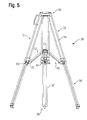
- Fig. 1a shows a spider 10 according to the invention in its use as a tripod.
- Fig. 1b the spider is connected to stabilize a tripod 20 with this.
- the spider comprises a main body 11 and three arms 12 pivotally connected thereto.
- the arms 12 are mounted pivotably on the main body 11 about a pivot axis 13 substantially perpendicular to their longitudinal extension.
- the arms 12 are composed in the illustrated embodiment of a first stage 14 and a second stage 15 together.
- the first stage is formed of two mutually parallel in cross-section circular rods or tubes 16, which are also referred to as legs of the first stage 14. These are connected to each other via a connecting element 17, which in turn is articulated about the axis 13 pivotally mounted on the base body 11. Other end of the legs 16, these are also connected via another element or guide member 18 with each other.
- this guide member 18 has a through hole (not shown) is formed through which the circular cross-section leg (rod or tube) 19 of the second stage 15 occurs and is guided.
- a plate 20 is fastened as a further guide element, which partially surrounds the legs 16 of the first step 14 on both sides of the leg 15 and thus supports the first leg 19 on both sides on these legs 16 (see FIG in this regard also the larger representation in Fig. 4 ).
- a clamping device 21 in the form of a screw is provided on the guide element 18 further, the head of which is manually operable.
- the screw By screwing the screw is moved in the radial direction of the leg 19 and presses either in the locked position so on the outer surface of the Leg 19 that this is fixed or moves a translationally movable jaw (see later description of the locking of the monopod), which then in turn in the locked position presses on the outer surface of the leg 19.
- a first locking element 22 (FIG. Fig. 2 ) designed.
- a further leg can be accommodated, which is relative to the leg 16, which is then configured as a hollow tube, telescopically displaceable and lockable in a corresponding relative position.
- the first locking element 22 is fastened to the leg 16 or an optionally further leg.
- a rubberized spike-like foot 27 is integrally provided at this end, which when using the spider 10 as a tripod ( Fig. 1a ) is used.
- a foot with a flat footprint preferably made of rubber, which is releasably attachable to the first locking element 22 and indeed in the same manner as this first locking element 22 with a pillar 31 of the tripod is lockable ( see following description).
- the tripod comprises a second locking element 23.
- the locking element 23 is attached to a first-stage connector 33 of a respective supporting leg 31 of the stand 30.
- the tripod legs 31 are configured similarly to the arms 12 of the spider. Ie.
- the first stage equally consists of two parallel legs 34, which are connected via the connecting piece 33 and a coupling piece 35 of the stand 30 for receiving a tripod head (see later).
- the second stage comprises two legs 37, the same as the one leg 19 of the arms 12 of the spider 10 are guided in the guide member 33.
- the tripod 30 may be equally designed as the spider 10 with only one leg 19 or the spider 10 instead of the leg 19 with two legs similar to the tripod leg 37.
- Other designs of telescopic legs, as they stand out are known in the art are conceivable, which also applies to the locking and clamping mechanisms for fixing the relative positions of the individual stages.
- the first locking element 22 is configured as a hollow cylinder in the illustrated embodiment and has a certain width or length in its longitudinal direction along the central axis 24 of the hollow cylinder.
- the second locking element 23 is equally configured as a hollow cylinder, however, designed to be longer in its overall width along the central axis of the hollow cylinder than the first locking element 22. Between the two ends of the hollow cylinder of the second locking element 23 is at least equal to the width of the hollow cylinder 22 and the length of the hollow cylinder of the second locking element 23 recessed in such a way that it is at most semicircular in cross-section in this area, so that the locking element 22 can be inserted into this recess or shell and thus completes the hollow cylinder.
- a locking pin 25th introduced so that it penetrates the cross-sectionally annular ends 26 of the second locking element 23 and through the hollow cylinder of the second locking element 22 and the two elements 22, 23 coupled.
- the connecting element 23 is shown only by dashed lines in order to better represent the lock, but actually lies in front of the Verrieglungselement or outside of these.
- the main body 11 of the spider 10 is further configured to define a receiving opening 28, which is a circular opening, to form a monopod 40 (FIG. Fig. 1c ) to be able to record.
- a clamping device 29 is provided to lock the monopod 40.
- a hand-operated screw 29 may be provided which, when screwed radially in the monopod 40, which is designed as a telescopic tube (see later) wanders and presses directly against the outer surface of the tube of the monopod 40 to lock it.
- a clamping on a lever cam connection is conceivable, which could equally well be used for the clamping device 21 of the arms 12 of the spider 10. Another variant will be related later Fig. 4 explained.
- the base body 11 is adapted to receive a tripod head 501 for receiving, for example, a camera.
- this preferably has a mounting preparation 50, which later with respect to Fig. 8 is explained.
- the tripod 30 has, as already mentioned, also three legs 31, each with two stages 32 and 36, wherein the first stage 32 and the legs 34 are connected about a hinge axis 39 pivotally connected to the coupling piece 35 of the stand 30.
- This pivot axis 39 runs equally as the pivot axis 13 substantially perpendicular to the longitudinal extent of the legs 31 (lever 41).
- the legs 31 at their opposite end equally feet 38 in the form of spikes.
- a preparation is made in order to mount feet with a flat footprint, preferably rubber feet (not shown) can replace the spikes in this case, although the spikes remain on the tripod.
- the in Fig. 1c monopod represented around a telescopic tube consisting of an outer tube 42 and an inner tube 43, which are displaceable relative to each other.
- the end face of the tube 42 opposite the base surface has an external thread onto which an outer ring 44 can be screwed.
- This outer ring 44 has an inner cone which presses on a corresponding oppositely directed counter-cone of an inner ring, not shown, when the outer ring 44 is screwed onto the thread.
- This inner ring presses in this state (tightened outer ring 44) radially on the inner tube 43 in order to fix this.
- an opening is also provided in the coupling piece 35 of the stand 30, which allows the monopod 40 and the tube 42 of the monopod 40 to be inserted and to use a mounting preparation 50 (see later).
- another clamping mechanism 45 is provided in the form of a lever which actuates a cam which may be integral or separate to the lever 45 and presses in the locked position of the lever against the outer surface of the tube 42 in its radial direction, to fix the pipe in the coupling piece 35 (see also later).
- the main body 11 of the spider 10 may, for. B. for receiving a 75 mm fluid head be configured, whereas the coupling piece 35 in addition to the possibility of receiving the monopod 40 for receiving a 100 mm fluid head suitable is.
- the essay of other tripod heads conceivable, for example via adapters or other mounting preparations 50.
- the basic modular set of the present invention is composed of the spider 10 and the tripod 30.
- This modular concept offers the possibility to use the spider 10 separately as an independent stand and to fix a tripod head 501 on the base body 11 or to insert the spider 10 in combination with the stand 30 and to connect it via the locking elements 22, 23 and the pin 25 and thereby stabilize the tripod 30.
- An extended set of the present invention further includes the monopod 40.
- This may be separate as in FIG Fig. 1c can be used by a tripod head 501 (possibly via a mounting preparation 50) is connected to it or alone with the tripod 30 (not shown) but preferably with the combination of tripod 30 and spider 10 ( Fig. 1d ).
- a tripod with extendable center post (monopod 40) is created.
- the spider 10 is used as a tripod, only a tripod head 501 must be fixed on the base body 11. If the spider 10 is used to stabilize the stand 30, it is locked only by the simple connection of the arms 12 with the legs 31 and the locking elements 22, 23 and 25. Then only the camera head 50 must be placed on the coupling piece 35. If the monopod 40 is used alone, it is merely connected to the tripod head 501. Should the combination be used as in Fig. 1d is shown, then the Spider 10, as described above, inserted into the stand 30 and the outer tube 42 is inserted through the opening in the coupling piece 35 of the stand 30 and guided by the receiving opening 28 of the main body 11 of the spider 10. For this purpose, the mounting preparations 50 are removed. If this combination is aligned accordingly, so that the legs of the stand 31 are correspondingly positioned on the ground, the legs or the arms of the stand 31 are fixed and the monopod 40 is clamped over the clamps 29 and 45.
- the modular structure consists of only a few parts, which are easy and easy to transport. For this purpose, it may be advantageous if the set is transported together in a common bag.
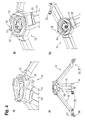
- Fig. 4 Spider shown differs from the one in Fig. 1a Spider shown in particular by the locking of the arms 12 with the legs 31 of the stand 30.
- the clamping device 25 for clamping the first and second stages of the legs 12 shown in more detail.
- the monopod 40 In addition to the later described locking of the spider 10 with the tripod 30 and the locking device 29 is designed to clamp the monopod 40 slightly different. So it is a provided with a handle 51, rotatably mounted bolt 52, which is provided at its the handle 51 opposite end with a thread. This thread engages an internal thread of a jaw 53. By the rotation of the bolt 52 via the handle 51, the jaw 53 is advanced in the radial direction of the outer tube 41 in order to clamp this. For this purpose, a predetermined maximum number of revolutions of the bolt 52 can do so serve to prevent too strong jamming. For example, this can be provided for a quarter turn or half a turn.
- the mounting preparation 50 is not used, which only serves for mounting a tripod head.
- the tripod head is placed on top of the base body 11 and comprises a protruding through the receiving opening 28 threaded screw (not shown). This engages in an internal thread 54 of the fastening device 50, which thus acts as a nut and is tightened over the handle portion 55 to fix the tripod head 501.
- the distributed over the circumference ribs 56 which are interrupted by recesses and outwardly projecting lugs 57, form latching hooks for temporarily holding the mounting preparation 50 in the receiving opening 28 in which engage the locking hooks on the inner circumference of the receiving opening 28 collar behind (see Fig. 4 ). With regard to the exact configuration of the attachment preparation 50, in particular Fig. 8 directed.
- the spider 10 is different Fig. 4 opposite to the illustrations Fig. 1a and 2 also by the first locking element.
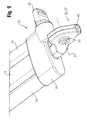
- This is still attached to the first stage 14 facing away from the end of the leg 19 (see in this regard, in particular also Fig. 9 ).
- a claw-shaped foot 27 extends from this end of the leg 19, a claw-shaped foot 27, the tip of which is formed of a spike-like rubber part 60.
- the first locking element 22 is integrated.
- This is formed by a hollow cylindrical through hole and penetrates the foot 27.
- the hollow cylindrical through hole has on both side edges of the foot 27 each have a collar 61.
- a hollow cylinder is pushed through the foot and protrudes on both Sides of the foot a certain distance from the side surfaces in front to form the collar.
- the first locking element 22 cooperates with the second locking element 23 provided on the stand Fig. 10 enlarged second locking element 23 is equally configured as a hollow cylinder, however, completely centered according to the width of the distance between the end faces of the collars 61, wherein both sides of the hollow cylinder in the recess semicircular or half-annular shoulder portions are provided.
- the pin 25 is biased in the locking position by a spring (not shown) and connected to a handle 63, over which against the spring force of the pin 25 can be pulled out of the recess 64.
- Fig. 10 is the pin 25, which protrudes into the recess not shown.
- Fig. 6 He is, however, out Fig. 6 seen.
- the foot 27 of the respective arm 12 of the spider 10 as in Fig. 4 is inserted correspondingly into the recess 64, it rests with the collars 61 of the first locking element 22 on the shoulders 62.
- the pin 25 is pulled against the spring force from the recess 64 via the handle 63.
- the handle 63 is released and the pin 25 engages on the spring force and penetrates the hollow cylindrical locking member 61 and the in Fig. 10 illustrated right hand of the recess 64 provided hollow cylindrical portion of the second locking member 23 to complete the coupling of the spider arm 12 with the tripod arm 31.
- a similar mounting preparation 50 as shown in Fig. 8 is shown and intended for the small tripod or the spider 10 is used. These can only be differ in size (diameter). However, the principle is the same, so it needs no further explanation.
- FIG. 7 the monopod 40 off Fig. 1c in perspective and an alternative embodiment.
- the monopod differs from the one in Fig. 1c represented, in particular by the clamping mechanism for locking the telescopic tubes 42 and 43.
- a lever 71 is used with an integrally formed cam 72, in the Fig. 7 In the illustrated locked position, the cam 72 compresses a slotted ring 73 to grip the outer circumference of the tube 43.
- the ring 73 with the lever 71 and the cam 72 is attached to the outer tube 42.
- the attachment of a tripod head 501 with the monopod 40 is carried out in a similar manner as in the spider 10 and the stand 30 via a mounting preparation 50, which is designed in principle the same, as in Fig. 10 represented so that it needs no further explanation.
- a spherical segment shaped rubberized portion 74 which is mounted on a lever 75 and its downwardly facing surface.
- the lever 75 is pivotably mounted about a pivot axis 76 in the outer tube 42, which extends substantially perpendicular to the longitudinal extent of the monopod 40.
- the lever 75 has a leg 77, which can be brought by pivoting the lever 75 about the axis 76 for engagement with the ground or ground, as shown in the illustration of Fig. 7c) is shown.
- the leg 77 serves to set up a foot, so that the lever 75 can also be referred to as a footrest. This can prevent turning of the tube when the camera is pivoted to the advantages of camera damping caused by the tripod head (fluid head) is fully utilized, without the monopod (Monopod) rotates and picks up the damping effect.
- the monopod 40 does not differ from that described above.
- the spider invention and the systems described above thus offer, in addition to the modular system that allows flexible operation first the possibility of camera support, especially for the reporter area, but also to absorb extreme sports, for documentations and z. B. in semi-professional area wedding videos without having to take a variety of different equipment.
Landscapes
- Engineering & Computer Science (AREA)
- General Engineering & Computer Science (AREA)
- Mechanical Engineering (AREA)
- Accessories Of Cameras (AREA)
- Load-Engaging Elements For Cranes (AREA)
- Mutual Connection Of Rods And Tubes (AREA)
Applications Claiming Priority (1)
| Application Number | Priority Date | Filing Date | Title |
|---|---|---|---|
| DE202007012585U DE202007012585U1 (de) | 2007-09-07 | 2007-09-07 | Spinne für ein Stativ und Set umfassend die Spinne sowie ein Dreibeinstativ |
Publications (3)
| Publication Number | Publication Date |
|---|---|
| EP2034231A2 true EP2034231A2 (fr) | 2009-03-11 |
| EP2034231A3 EP2034231A3 (fr) | 2009-12-16 |
| EP2034231B1 EP2034231B1 (fr) | 2013-02-13 |
Family
ID=38806442
Family Applications (1)
| Application Number | Title | Priority Date | Filing Date |
|---|---|---|---|
| EP08160080A Not-in-force EP2034231B1 (fr) | 2007-09-07 | 2008-07-10 | Croisillon pour un statif et kit comprenant un croisillon et un trépied |
Country Status (5)
| Country | Link |
|---|---|
| US (1) | US8534620B2 (fr) |
| EP (1) | EP2034231B1 (fr) |
| JP (1) | JP5186312B2 (fr) |
| CN (1) | CN101382231B (fr) |
| DE (1) | DE202007012585U1 (fr) |
Families Citing this family (60)
| Publication number | Priority date | Publication date | Assignee | Title |
|---|---|---|---|---|
| ITPD20040005A1 (it) * | 2004-01-16 | 2004-04-16 | Lino Manfrotto & Co Spa | Treppiede compatto |
| DE202007012585U1 (de) | 2007-09-07 | 2007-12-06 | Camera Dynamics Gmbh | Spinne für ein Stativ und Set umfassend die Spinne sowie ein Dreibeinstativ |
| DE102009010460B4 (de) * | 2009-02-13 | 2010-11-25 | Pilz Gmbh & Co. Kg | Vorrichtung und Verfahren zum Bestimmen der Nachlaufzeit einer Maschine |
| WO2010111544A1 (fr) * | 2009-03-25 | 2010-09-30 | Brunson Instrument Company | Trépied de poids léger de qualité métrologique |
| DE202009006644U1 (de) | 2009-05-07 | 2009-07-23 | Camera Dynamics Gmbh | Mittelspinne |
| ATE537404T1 (de) | 2009-05-11 | 2011-12-15 | Camera Dynamics Gmbh | Stativ, insbesondere kamerastativ |
| WO2010140203A1 (fr) * | 2009-06-01 | 2010-12-09 | ベルボン株式会社 | Dispositif à pieds |
| US8047498B1 (en) * | 2010-07-19 | 2011-11-01 | Marcus Karty | Support stand device for rebar bender |
| CN101956892B (zh) * | 2010-08-27 | 2012-09-05 | 中山立信摄影器材有限公司 | 云台锁紧装置 |
| US20130038770A1 (en) * | 2011-08-10 | 2013-02-14 | James Hawkins | Sports Video Training Accessory |
| US20130134268A1 (en) * | 2011-11-26 | 2013-05-30 | Grifiti Llc | Multiuse Monopod Device Mounting System and Method |
| CN102927418A (zh) * | 2012-11-13 | 2013-02-13 | 李长皓 | 稳定型相机架 |
| CN102944702B (zh) * | 2012-11-14 | 2015-05-20 | 国家电网公司 | 升降式高压试验高空接线钳装置 |
| CN103149779A (zh) * | 2013-03-28 | 2013-06-12 | 中山市思锐摄影器材工业有限公司 | 一种用于摄影脚架上的可拆中轴 |
| US8991777B2 (en) * | 2013-04-23 | 2015-03-31 | Gabriel Madril | Post stabilization apparatus and method |
| ITPD20130154A1 (it) * | 2013-05-31 | 2014-12-01 | Gitzo Sa | Supporto per apparecchiature fotografiche |
| CN105705855B (zh) * | 2013-10-30 | 2018-06-22 | I·本梅尔 | 具有快速打开和关闭机构的三脚架及使用方法 |
| CN105708626B (zh) * | 2014-07-06 | 2019-01-25 | 安徽承庆堂国药股份有限公司 | 一种提高理疗贴的粘贴效果及药性的方法 |
| CN104146833B (zh) * | 2014-07-06 | 2016-08-17 | 储诚浩 | 医疗和美容用理疗贴加热装置 |
| GB2536719B (en) * | 2015-03-27 | 2018-12-05 | Vitec Group Plc | A Tripod leg |
| CN105276471B (zh) * | 2015-11-05 | 2018-06-22 | 海门黄海创业园服务有限公司 | 一种可调节的植物补光灯 |
| CN105240666B (zh) * | 2015-11-10 | 2017-06-16 | 北京理工大学珠海学院 | 一种测绘仪器三脚架半自动调整装置及测绘仪器三脚架 |
| CN105605384A (zh) * | 2016-01-27 | 2016-05-25 | 长治清华机械厂 | 可折叠支撑机构 |
| US9675146B1 (en) * | 2016-03-14 | 2017-06-13 | John D. Howell | Free-standing support system |
| IT201600090691A1 (it) * | 2016-09-08 | 2018-03-08 | Cartoni S P A | Stella perfezionata per treppiedi video-fotografici. |
| CN106767729A (zh) * | 2016-11-16 | 2017-05-31 | 成都佳美嘉科技有限公司 | 一种工程测量用三角架 |
| CN106764311A (zh) * | 2017-03-17 | 2017-05-31 | 天津商业大学 | 一种可自由调节支腿宽度的望远镜支架 |
| TWI619630B (zh) * | 2017-07-03 | 2018-04-01 | Base of bicycle hanger | |
| CN108050356A (zh) * | 2018-01-18 | 2018-05-18 | 北京强氧新科信息技术有限公司 | 一种vr系统 |
| CN108870012A (zh) * | 2018-07-10 | 2018-11-23 | 陈晓骏 | 一种相机三脚架云台 |
| CN108870025A (zh) * | 2018-07-12 | 2018-11-23 | 储海霞 | 一种三脚架云台 |
| CA3053026A1 (fr) | 2018-09-07 | 2020-03-07 | Signalisation D'urgence Rh Inc. | Dispositif d`alarme escamotable et procede pour emettre un signal lumineux |
| CN109340543B (zh) * | 2018-12-21 | 2021-04-06 | 天津博泰天宇科技发展有限公司 | 一种单扳把双级联控可调整抱箍式摄像机承载架体 |
| CN109667436A (zh) * | 2018-12-31 | 2019-04-23 | 宁波二十冶建设有限公司 | 一种多功能移动三脚架及使用方法 |
| US11067216B2 (en) * | 2019-01-04 | 2021-07-20 | Really Right Stuff, Llc | Tripod with a sealed leg lock |
| CN109654352B (zh) * | 2019-01-04 | 2020-08-14 | 瑞安市兆达机车部件有限公司 | 一种移动式测速仪的支腿结构 |
| USD974453S1 (en) * | 2019-01-25 | 2023-01-03 | Guangdong Sirui Optical Co., Ltd. | Tripod |
| WO2020220203A1 (fr) * | 2019-04-29 | 2020-11-05 | 深圳市大疆创新科技有限公司 | Dispositif de connexion et système de cardan |
| US11067225B2 (en) * | 2019-07-08 | 2021-07-20 | Tianjin Botai Tianyu Science And Technology Development Company Limited | Single-hand-lever double-joint-control adjustable hoop type bearing frame |
| CN110242843B (zh) * | 2019-07-22 | 2020-09-25 | 朱建华 | 一种改进的工程测绘用测绘仪定位装置 |
| CN110410632B (zh) * | 2019-07-24 | 2021-10-01 | 李文正 | 一种带防抖动装置的三维成像用扫描仪 |
| USD916174S1 (en) * | 2019-07-25 | 2021-04-13 | Qiu Gong | Tripod |
| US11141020B2 (en) * | 2019-08-14 | 2021-10-12 | Jeffrey Eno | Tripodal cooking assembly |
| JP7352465B2 (ja) * | 2019-12-27 | 2023-09-28 | 株式会社トプコン | 三脚装置 |
| CN111022858A (zh) * | 2019-12-27 | 2020-04-17 | 天津中安视通科技有限公司 | 一种新型云台摄像机安装装置 |
| CN111396697B (zh) * | 2020-03-18 | 2021-11-12 | 重庆三峡学院 | 一种土木工程测量仪器用支架 |
| WO2021251156A1 (fr) | 2020-06-10 | 2021-12-16 | ソニーグループ株式会社 | Train d'atterrissage |
| CN212617357U (zh) * | 2020-06-10 | 2021-02-26 | 源德盛塑胶电子(深圳)有限公司 | 一种三脚架 |
| USD962327S1 (en) * | 2020-06-23 | 2022-08-30 | Yuzhen Zhong | Camera holder |
| CN112682667B (zh) * | 2021-01-06 | 2022-10-18 | 青海省水文地质工程地质环境地质调查院 | 可提高测绘精度的测绘仪器用支架 |
| USD1066465S1 (en) * | 2021-02-01 | 2025-03-11 | Yueqing Youyou E-Commerce Co., Ltd. | Tripod |
| IT202100005627A1 (it) * | 2021-03-10 | 2022-09-10 | Vitec Imaging Solutions S P A | Stativo a colonna, particolarmente per il supporto di impianti di illuminazione od acustici |
| CN113586904A (zh) * | 2021-07-01 | 2021-11-02 | 浙江启富建设有限公司 | 一种房建装修用远程通讯激光扫描仪 |
| EP4370869A4 (fr) | 2021-07-15 | 2025-07-23 | Milwaukee Electric Tool Corp | Support pour outil de projection laser |
| CN114526424A (zh) * | 2022-02-24 | 2022-05-24 | 诺文科智能通风研究院(西安)有限公司 | 井下钻探分析用可插入防倒的视频监控设备及实施方法 |
| WO2023169379A1 (fr) * | 2022-03-06 | 2023-09-14 | 深圳市豪华联合科技有限公司 | Pied de support télescopique, support à pieds multiples et support de photographie |
| USD1077894S1 (en) * | 2022-05-02 | 2025-06-03 | Zhilian Xia | Video camera stand |
| CN115199913B (zh) * | 2022-07-07 | 2024-04-26 | 陕西恒昌铁路工程有限公司 | 一种跨铁路线桥梁承台基础定点装置 |
| CN221592442U (zh) * | 2023-11-20 | 2024-08-23 | 宁波琅睿科技有限公司 | 一种联动锁紧的伸缩三脚架 |
| US12372225B1 (en) * | 2024-05-15 | 2025-07-29 | Devos, LLC | Tripod for pole mounted lantern |
Family Cites Families (26)
| Publication number | Priority date | Publication date | Assignee | Title |
|---|---|---|---|---|
| US83393A (en) * | 1868-10-27 | Improvement in pintle of butt-hing-e | ||
| US1099505A (en) * | 1914-01-08 | 1914-06-09 | Francis W Smith | Support. |
| US1392144A (en) * | 1921-06-02 | 1921-09-27 | Samuel R Gray | Portable camera-support |
| US1517825A (en) * | 1923-06-21 | 1924-12-02 | Bruneau Eugene | Tripod |
| US2160538A (en) * | 1938-02-08 | 1939-05-30 | Cavuoti Frank | Camera tripod brace |
| US2277939A (en) * | 1939-08-07 | 1942-03-31 | Thomas W Sukumlyn | Leg rest |
| US2262939A (en) * | 1941-05-03 | 1941-11-18 | Julius G Howard | Adjustable tripod leg |
| US2282285A (en) * | 1941-05-16 | 1942-05-05 | Folmer Graflex Corp | Camera stand or tripod |
| US2467005A (en) * | 1947-11-26 | 1949-04-12 | Belanoff Robert | Tripod stabilizer |
| GB1492394A (en) * | 1974-03-26 | 1977-11-16 | Elliott Bros | Tripod arrangements |
| DE2845509A1 (de) * | 1978-10-19 | 1980-04-30 | Alois Segerer | Stativ, insbesondere fuer foto- und filmkameras |
| US4570886A (en) * | 1982-11-18 | 1986-02-18 | Mooney Paul C | Locking mechanism for tripod and spreader legs |
| DE3805262A1 (de) | 1988-02-19 | 1989-08-31 | Kuerbi & Niggeloh | Stativ |
| DE3805260A1 (de) | 1988-02-19 | 1989-08-31 | Kuerbi & Niggeloh | Stativ |
| DE9108498U1 (de) * | 1991-07-10 | 1991-10-17 | Sachtler Ag - Kommunikationstechnik, 8046 Garching | Mittelspinne für Dreibeinstative |
| JPH06265093A (ja) * | 1993-03-10 | 1994-09-20 | Sony Corp | 三脚装置 |
| JP3512484B2 (ja) * | 1994-10-07 | 2004-03-29 | 株式会社トプコン | 測量用三脚のスライド脚ずれ防止装置 |
| US5531438A (en) * | 1994-10-26 | 1996-07-02 | Corley; Deryl | Batting practice device |
| US5769370A (en) * | 1995-12-29 | 1998-06-23 | Javad Positioning, Llc | Knock-down satellite positioning system antenna supporting tripod |
| IL134285A0 (en) * | 2000-01-30 | 2001-04-30 | Sherwin Daniel | Tripod |
| US6438800B1 (en) * | 2001-01-22 | 2002-08-27 | General Electric Company | Door hinge assembly for an electrical appliance enclosure |
| ITPD20010180A1 (it) * | 2001-07-17 | 2003-01-17 | Manfrotto Lino & C Spa | Stabilizzatore ad aste telescopiche per treppiedi e simili. |
| US7631842B2 (en) * | 2002-04-19 | 2009-12-15 | Seco Manufacturing Company, Inc. | Modular geomatic pole support system |
| US20060086869A1 (en) * | 2004-10-26 | 2006-04-27 | Wu-Hong Hsieh | Tripod for a musical instrument |
| DE202006014419U1 (de) | 2006-09-20 | 2006-11-09 | Unomat Gmbh & Co. Kg | Zerlegbares Stativ |
| DE202007012585U1 (de) | 2007-09-07 | 2007-12-06 | Camera Dynamics Gmbh | Spinne für ein Stativ und Set umfassend die Spinne sowie ein Dreibeinstativ |
-
2007
- 2007-09-07 DE DE202007012585U patent/DE202007012585U1/de not_active Expired - Lifetime
-
2008
- 2008-07-10 EP EP08160080A patent/EP2034231B1/fr not_active Not-in-force
- 2008-08-28 CN CN2008102111605A patent/CN101382231B/zh active Active
- 2008-09-03 JP JP2008225373A patent/JP5186312B2/ja not_active Expired - Fee Related
- 2008-09-05 US US12/205,812 patent/US8534620B2/en not_active Expired - Fee Related
Non-Patent Citations (1)
| Title |
|---|
| None |
Also Published As
| Publication number | Publication date |
|---|---|
| CN101382231A (zh) | 2009-03-11 |
| JP2009063167A (ja) | 2009-03-26 |
| JP5186312B2 (ja) | 2013-04-17 |
| DE202007012585U1 (de) | 2007-12-06 |
| EP2034231B1 (fr) | 2013-02-13 |
| US8534620B2 (en) | 2013-09-17 |
| EP2034231A3 (fr) | 2009-12-16 |
| US20090072100A1 (en) | 2009-03-19 |
| CN101382231B (zh) | 2012-09-05 |
Similar Documents
| Publication | Publication Date | Title |
|---|---|---|
| EP2034231B1 (fr) | Croisillon pour un statif et kit comprenant un croisillon et un trépied | |
| DE60211032T2 (de) | Dreibeinstativ zum tragen von geräten, insbesondere von optischen oder photographischen geräten und dergleichen | |
| DE602004013219T2 (de) | Verlängerungsstiel zum Betätigen eines Handwerkzeugs | |
| DE4239405C2 (de) | Stativ für eine Foto-oder Videokamera | |
| DE102016005652B3 (de) | Gestell für eine Hängematte | |
| DE69123157T2 (de) | Dreibeinstativ | |
| DE3127145A1 (de) | Befestigungsvorrichtung mit zwei schwenkbar miteinander verbundenen klemmen | |
| DE102011015351A1 (de) | Modulares Ständerwerk und Verbindungszylinder | |
| DE102013013819A1 (de) | Schnellspanner | |
| DE2902419A1 (de) | Stativ fuer optische geraete, insbesondere kameras | |
| DE69800303T2 (de) | Kupplungselement zur Verbindung von zwei senkrecht zueinander angeordneten Stangen | |
| DE2050264B2 (de) | Vorrichtung zum Befestigen eines Rohrstückes zwischen zwei Bögen | |
| EP3144544A1 (fr) | Systeme d'articulation destine au positionnement de composants | |
| WO2010127905A2 (fr) | Triangle intermédiaire | |
| EP2110208B1 (fr) | Tige de télescope dotée d'un dispositif d'arrêt | |
| EP1022397A1 (fr) | Barre murale pivotante pour douches | |
| DE2656872C2 (de) | Ständer mit verstellbarem Schrägarm | |
| DE10341153B4 (de) | Ständer | |
| DE102007010061B4 (de) | Montagehilfsvorrichtung zur Unterstützung der Montage eines hülsenförmigen Verkleidungsteiles in einem ringförmigen Gehäuse eines Gerätes zur medizinischen Bildgebung und Gerät zur medizinischen Bildgebung mit einer solchen Montagehilfsvorrichtung | |
| DE2604971A1 (de) | Vorrichtung und verfahren zum haltern von schlaginstrumenten und deren zubehoer | |
| EP1723942B1 (fr) | Connecteur pour cannes anglaises et cannes avec connecteur | |
| DE3733956A1 (de) | Stativ fuer optische geraete | |
| AT166099B (de) | Verschalungsstütze | |
| EP1634774B1 (fr) | Porte-charge pour un dispositif d'attelage rétractable | |
| DE10018275A1 (de) | Kamera und Aufhängevorrichtung für Kamera |
Legal Events
| Date | Code | Title | Description |
|---|---|---|---|
| PUAI | Public reference made under article 153(3) epc to a published international application that has entered the european phase |
Free format text: ORIGINAL CODE: 0009012 |
|
| AK | Designated contracting states |
Kind code of ref document: A2 Designated state(s): AT BE BG CH CY CZ DE DK EE ES FI FR GB GR HR HU IE IS IT LI LT LU LV MC MT NL NO PL PT RO SE SI SK TR |
|
| AX | Request for extension of the european patent |
Extension state: AL BA MK RS |
|
| PUAL | Search report despatched |
Free format text: ORIGINAL CODE: 0009013 |
|
| AK | Designated contracting states |
Kind code of ref document: A3 Designated state(s): AT BE BG CH CY CZ DE DK EE ES FI FR GB GR HR HU IE IS IT LI LT LU LV MC MT NL NO PL PT RO SE SI SK TR |
|
| AX | Request for extension of the european patent |
Extension state: AL BA MK RS |
|
| 17P | Request for examination filed |
Effective date: 20100205 |
|
| 17Q | First examination report despatched |
Effective date: 20100628 |
|
| AKX | Designation fees paid |
Designated state(s): DE ES FR GB IT |
|
| GRAP | Despatch of communication of intention to grant a patent |
Free format text: ORIGINAL CODE: EPIDOSNIGR1 |
|
| GRAS | Grant fee paid |
Free format text: ORIGINAL CODE: EPIDOSNIGR3 |
|
| GRAA | (expected) grant |
Free format text: ORIGINAL CODE: 0009210 |
|
| AK | Designated contracting states |
Kind code of ref document: B1 Designated state(s): DE ES FR GB IT |
|
| REG | Reference to a national code |
Ref country code: GB Ref legal event code: FG4D Free format text: NOT ENGLISH |
|
| REG | Reference to a national code |
Ref country code: DE Ref legal event code: R096 Ref document number: 502008009223 Country of ref document: DE Effective date: 20130411 |
|
| PG25 | Lapsed in a contracting state [announced via postgrant information from national office to epo] |
Ref country code: ES Free format text: LAPSE BECAUSE OF FAILURE TO SUBMIT A TRANSLATION OF THE DESCRIPTION OR TO PAY THE FEE WITHIN THE PRESCRIBED TIME-LIMIT Effective date: 20130524 |
|
| PLBE | No opposition filed within time limit |
Free format text: ORIGINAL CODE: 0009261 |
|
| STAA | Information on the status of an ep patent application or granted ep patent |
Free format text: STATUS: NO OPPOSITION FILED WITHIN TIME LIMIT |
|
| PG25 | Lapsed in a contracting state [announced via postgrant information from national office to epo] |
Ref country code: IT Free format text: LAPSE BECAUSE OF FAILURE TO SUBMIT A TRANSLATION OF THE DESCRIPTION OR TO PAY THE FEE WITHIN THE PRESCRIBED TIME-LIMIT Effective date: 20130213 |
|
| 26N | No opposition filed |
Effective date: 20131114 |
|
| REG | Reference to a national code |
Ref country code: DE Ref legal event code: R097 Ref document number: 502008009223 Country of ref document: DE Effective date: 20131114 |
|
| REG | Reference to a national code |
Ref country code: FR Ref legal event code: PLFP Year of fee payment: 8 |
|
| PGFP | Annual fee paid to national office [announced via postgrant information from national office to epo] |
Ref country code: FR Payment date: 20150630 Year of fee payment: 8 |
|
| PG25 | Lapsed in a contracting state [announced via postgrant information from national office to epo] |
Ref country code: FR Free format text: LAPSE BECAUSE OF NON-PAYMENT OF DUE FEES Effective date: 20160801 |
|
| REG | Reference to a national code |
Ref country code: FR Ref legal event code: ST Effective date: 20170331 |
|
| REG | Reference to a national code |
Ref country code: DE Ref legal event code: R081 Ref document number: 502008009223 Country of ref document: DE Owner name: VIDENDUM PRODUCTION SOLUTIONS GMBH, DE Free format text: FORMER OWNER: CAMERA DYNAMICS GMBH, 85386 ECHING, DE |
|
| P01 | Opt-out of the competence of the unified patent court (upc) registered |
Effective date: 20230426 |
|
| PGFP | Annual fee paid to national office [announced via postgrant information from national office to epo] |
Ref country code: DE Payment date: 20240717 Year of fee payment: 17 |
|
| PGFP | Annual fee paid to national office [announced via postgrant information from national office to epo] |
Ref country code: GB Payment date: 20240715 Year of fee payment: 17 |
|
| REG | Reference to a national code |
Ref country code: DE Ref legal event code: R119 Ref document number: 502008009223 Country of ref document: DE |
|
| GBPC | Gb: european patent ceased through non-payment of renewal fee |
Effective date: 20250710 |
|
| PG25 | Lapsed in a contracting state [announced via postgrant information from national office to epo] |
Ref country code: GB Free format text: LAPSE BECAUSE OF NON-PAYMENT OF DUE FEES Effective date: 20250710 |
|
| PG25 | Lapsed in a contracting state [announced via postgrant information from national office to epo] |
Ref country code: DE Free format text: LAPSE BECAUSE OF NON-PAYMENT OF DUE FEES Effective date: 20260203 |